
Technical publication
Back to publications
Reactors & equipment
Calculations of Hydrodynamic Cavitation Devices
okozyuk.com
Published
Read complete publication for whole-document Find and printing. Browser Find and native printing on this reader include only loaded content.
6 Selection of Structural Materials
Structural material selection for a cavitation device cannot be reduced to a single alloy ranking. The pressure boundary, cavitation generating insert, rotor, shaft, wear plate, fastener, seal face, gasket, and product contact surface perform different functions. Pressure retaining walls require weldability and code allowable stress; removable inserts require erosion resistance and dimensional stability; rotors require fatigue strength and balance; and sanitary surfaces require corrosion resistance, cleanability, low metal release, and controlled finish. Assigning all functions to one material can increase cost while reducing lifecycle performance [22–27].
The preferred design strategy first controls the hydraulic collapse location, then assigns replaceable wear components, and only afterward considers alloy or coating upgrades. No practical material is immune to sufficiently aggressive cavitation. A hard surface may resist plastic indentation but fail by brittle cracking or coating delamination. A corrosion resistant alloy can repeatedly lose its passive film under impact, while a tough alloy may deform and work harden but release metal. Material selection must therefore reflect the actual chemistry, temperature, solids, gas content, pressure history, geometry, permitted contamination, and inspection interval [23–25].
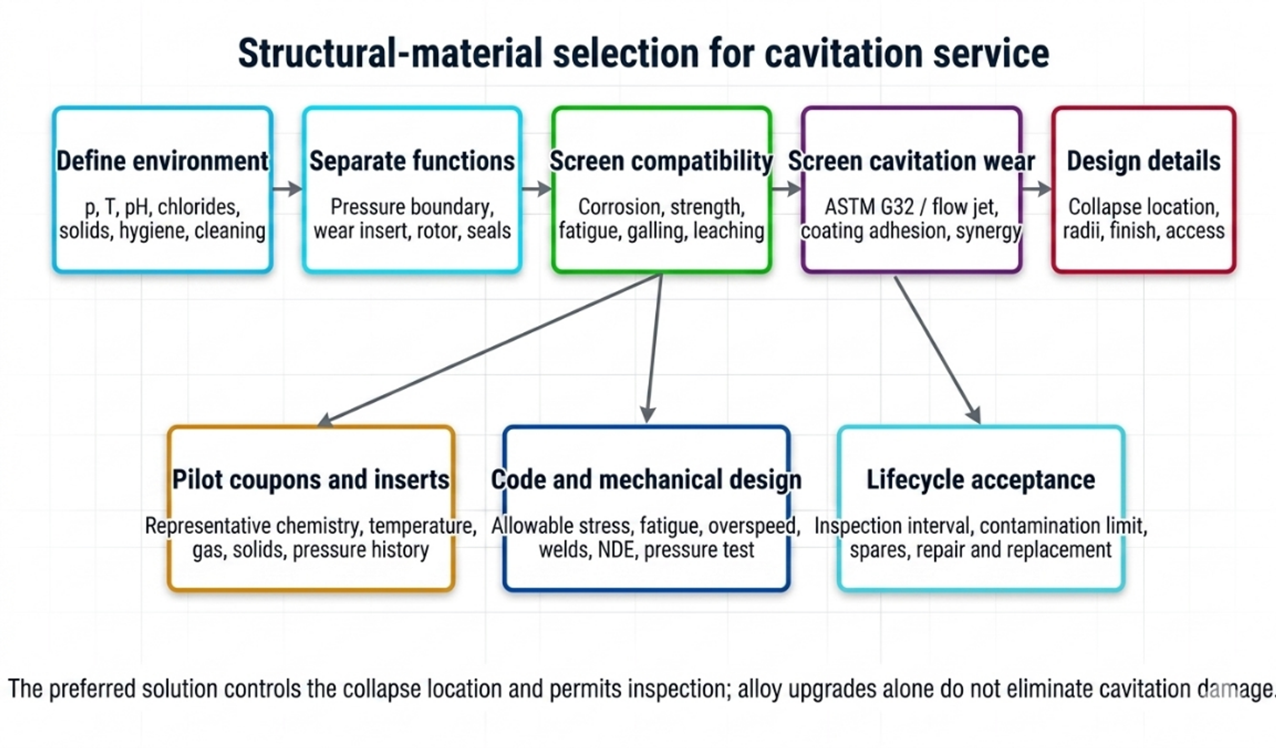
Figure 6.1. Structural material selection workflow for hydrodynamic cavitation equipment [32].
6.1 Functional decomposition of the device
The calculation package should identify the material function of every component:
Pressure boundary: contains maximum allowable working pressure, relief pressure, vacuum, thermal load, and piping reaction.
Cavitation insert or throat: defines the hydraulic geometry and may be intentionally replaceable.
Collapse chamber or wear plate: receives the highest expected microjet and cloud collapse loading.
Rotor and shaft: resist centrifugal stress, torque, fatigue, corrosion, and erosion while maintaining balance.
Stator and clearance surfaces: maintain geometry under pressure, temperature, and possible rub.
Seals, gaskets, and bearings: remain compatible with chemistry and temperature while preventing product contamination.
Welds and heat affected zones: meet pressure code, corrosion, fatigue, and surface finish requirements.
Instrumentation connections: avoid crevices, dead legs, thin diaphragms exposed to collapse, and plugged impulse lines.
A replaceable insert allows the pressure shell to be selected primarily for code, corrosion, and fabrication, while the wear component is selected for cavitation exposure. The insert should have positive location, repeatable dimensions, no bypass leakage, and an inspection datum. Its failure must not release a loose part into downstream equipment.
6.2 Pressure boundary screening
For a cylindrical wall under internal pressure, a simplified thin wall screen can be written:
where is design pressure, is the selected diameter basis, is allowable stress, and is weld joint efficiency. Equation (6.1) is only a preliminary screen. Final thickness, reinforcement, flange rating, fatigue, external pressure, nozzle loads, weld details, examination, testing, and material allowable must comply with the applicable pressure vessel or piping code, such as ASME BPVC Section VIII or ASME B31.3 [26, 27].
A practical nominal thickness expression is:
where is code required thickness, is corrosion allowance, is a justified erosion allowance, is machining or resurfacing allowance, and is the negative mill tolerance fraction. An erosion allowance should not replace inspection or a wear insert when cavitation attack is localized.
Worked structural screen
For MPa, m, MPa, and , Equation (6.1) gives mm. This small value illustrates only membrane pressure demand. It is not a final wall thickness. A real device may require substantially more thickness for code minimums, threading, nozzles, flange loads, cyclic pressure, vibration, manufacturing tolerance, corrosion, erosion, and rigidity needed to preserve a small internal clearance.
6.3 Cavitation erosion and erosion corrosion interaction
Cavitation erosion is produced by repeated pressure pulses, microjets, cloud collapse, and associated cyclic deformation. The incubation period may show little measurable mass loss while subsurface fatigue accumulates. It can be followed by an accelerating stage, a maximum rate, and a later rate modified by roughness and the evolving flow. A single test duration can therefore misrepresent long term behavior [23, 24].
ASTM G32 provides a vibratory apparatus method for comparative cavitation erosion testing [23]. Its output is valuable for screening materials, heat treatments, and coatings under controlled conditions, but it should not be converted directly into plant service life. A hydrodynamic device has different impact frequency, bubble cloud scale, pressure recovery, chemistry, temperature, solids, and wall geometry. The strongest program combines standardized comparison, a representative flow test, and pilot inserts in the actual process.
Mean depth of erosion calculated from mass loss is:
where is mass loss, is solid density, and is exposed area. The mean depth penetration rate is:
A combined erosion corrosion loss may be expressed conceptually as:
where is purely mechanical cavitation loss, is corrosion loss without cavitation, and is the interaction term. The interaction can be positive because impact removes passive films and corrosion weakens the surface, but the sign and magnitude must be measured for the actual environment [24].
For an observed approximately linear penetration rate after incubation, a remaining life screen is:
where is the maximum permitted local penetration and is measured penetration. This calculation is valid only when the rate is stable and the measured location corresponds to the most severe attack. Local pits or crack like defects may govern before average depth.
6.4 Material property requirements
Cavitation resistance is influenced by hardness, yield strength, strain hardening, toughness, fatigue behavior, elastic modulus, microstructure, residual stress, phase stability, corrosion resistance, surface finish, and defect population. No single property predicts performance across all regimes. The desired combination is a surface that resists repeated indentation and cracking, a substrate that supports the surface without excessive deformation, and a chemistry that maintains passivity or avoids rapid dissolution [24, 25].
Material screening should consider:
Strength and fatigue: pressure cycles, rotor stress, passage frequency loading, and vibration.
Toughness: resistance to crack initiation and propagation under repeated impact.
Hardness and work hardening: resistance to plastic indentation, with attention to brittle failure.
Corrosion: uniform corrosion, pitting, crevice corrosion, stress corrosion cracking, galvanic coupling, and corrosion fatigue.
Fabrication: weldability, heat treatment, distortion, machinability, repair, and nondestructive examination.
Surface condition: roughness, inclusions, machining marks, weld profile, coating defects, and residual stress.
Process compatibility: extractables, toxic metal limits, food or pharmaceutical conformity, product discoloration, and catalyst poisoning.
Lifecycle: cost, lead time, replaceability, inspection method, and disposal or repair.
6.5 Candidate metallic materials
Table 6.1. Qualitative material selection matrix for cavitation devices.
| Material family | Potential role | Principal advantages | Principal cautions |
|---|---|---|---|
| Carbon and low alloy steel | External pressure shell or nonhygienic benign service | Low cost, strength, weldability, code familiarity | Corrosion products, product contamination, localized erosion corrosion, coating dependence |
| 304L austenitic stainless steel | Mild sanitary or water service | Fabricability, cleanability, availability | Lower chloride pitting margin than Mo bearing grades; not immune to cavitation |
| 316L austenitic stainless steel | Common hygienic pressure boundary and wetted components | Weldability, cleanability, improved pitting resistance over 304L | Can pit or crevice corrode in hot chlorides; moderate hardness; erosion can remove passive film |
| Duplex stainless steel 2205 | Higher strength chloride service, pressure parts, selected rotors | Higher strength and chloride resistance than common austenitic grades | Phase balance and welding control; surface finishing and hygienic qualification require care |
| Super duplex or high alloy austenitic steel | Severe chloride or oxidizing aqueous service | High pitting and crevice corrosion resistance | Cost, fabrication control, availability, possible over specification if erosion dominates |
| Martensitic or precipitation hardening stainless steel | Shafts, rotors, replaceable wear parts | Higher strength and hardness after heat treatment | Lower corrosion resistance in some chemistries; heat treatment control; not automatically suitable for sanitary contact |
| Nickel base corrosion resistant alloy | Strong acids, mixed chemicals, severe corrosion | Broad corrosion resistance in selected environments | High cost, galling, density, weld procedure, chemistry specific limitations |
| Titanium alloy | Chloride rich service, low density rotor or wetted component | Low density and strong passive behavior in many chloride environments | Galling, galvanic coupling, hydrogen effects, fabrication cost; cavitation resistance remains condition dependent |
| Cobalt base or nickel base hard facing | Local replaceable wear surface | Hardness, work hardening or high temperature wear capability | Cracking, dilution, repair, cost, possible metal release restrictions |
| Copper alloy | Specialized marine or antimicrobial service | Thermal conductivity and selected seawater applications | Metal release, galvanic effects, chemistry limitations, generally unsuitable where copper contamination is unacceptable |
The table is a screening matrix, not a substitution rule. The specific grade, product form, heat treatment, weld, surface finish, and service chemistry determine performance. Material certificates and positive material identification should be tied to the component drawing.
6.6 Coatings, surface treatments, and claddings
Coatings can increase surface hardness or corrosion resistance while retaining a tough structural substrate. Candidate technologies include physical vapor deposited nitrides, high velocity oxy fuel coatings, weld overlays, laser cladding, nitriding, shot peening, and engineered surface remelting. A recent study of CrN coated 316L illustrates that coating architecture can improve comparative cavitation behavior, but the result depends on adhesion, residual stress, porosity, substrate support, and the test environment [25].
A coating qualification should include:
-
substrate grade, heat treatment, and surface preparation;
-
coating composition, thickness, hardness, porosity, and residual stress;
-
adhesion and edge condition;
-
cavitation test before and after chemical exposure;
-
thermal cycle and clean in place compatibility;
-
inspection method for pinholes, cracks, and delamination;
-
permitted particle or metal release;
-
repair procedure and dimensional effect.
A very hard thin coating on a compliant substrate can crack when repeated pressure pulses deform the substrate. A thick sprayed coating can contain pores and reduce a small hydraulic clearance. Coating a sharp orifice edge can change its radius and discharge coefficient. The final hydraulic geometry should therefore be measured after coating.
6.7 Ceramics and cermets
Technical ceramics and cermets offer high hardness and corrosion resistance but are sensitive to tensile stress, impact defects, thermal shock, and attachment details. They are better suited to compressively supported inserts, sleeves, nozzles, or tiles than to complex unsupported pressure boundaries. A ceramic insert should have generous radii, controlled interference or compliant support, and protection against assembly impact. The consequences of fragment release must be considered for food, pharmaceutical, turbine, membrane, and precision downstream equipment.
Tungsten carbide and chromium carbide systems may be used as bulk inserts or sprayed coatings, but binder chemistry and galvanic behavior must match the process. Hardness alone does not guarantee cavitation life because binder removal, pore attack, and brittle grain pullout can control failure.
6.8 Elastomers, polymers, seals, and bearings
Elastomer selection is governed by the complete fluid mixture, temperature, pressure, cleaning chemicals, oxidants, solvent swelling, gas decompression, and regulatory status. EPDM, FKM, FFKM, nitrile, silicone, and PTFE based materials have distinct compatibility envelopes; no generic ranking is valid for all cavitation applications. Compatibility should be confirmed using supplier data and immersion or compression testing in the actual process and cleaning fluids.
Seals should be located away from the strongest collapse zone and pressure pulsation where possible. A dynamic seal calculation should include chamber pressure, shaft speed, heat generation, face loading, flush plan, solids, gas, and dry running risk. Double mechanical seals or barrier systems may be required when product containment, air exclusion, or hazardous chemistry governs. Bearings should be isolated from process liquid unless they are specifically designed as product lubricated components.
Thermoplastics can be useful for transparent development chambers, low pressure inserts, or corrosion isolation, but pressure rating, creep, solvent compatibility, temperature, ultraviolet exposure, and brittle fracture must be checked. A transparent chamber used for visualization should have a protective enclosure and a defined service life.
6.9 Hygienic and cleanable construction
Food and pharmaceutical devices should use cleanable geometry, compatible product contact materials, controlled surface finish, drainability, and validated cleaning. Inline rotor stator equipment may be evaluated against applicable 3-A requirements, but the owner remains responsible for the complete installation, including piping, seals, instrumentation, and cleaning cycle [22].
Important design details include:
-
continuous welds with controlled penetration and ground or polished product surfaces where required;
-
no gasket intrusion into the flow path;
-
elimination of dead legs and unvented high points;
-
drainable housings and sample ports;
-
accessible or validated internal cavities;
-
surface finish measurement after fabrication and repair;
-
avoidance of threaded product contact joints unless specifically accepted;
-
material and elastomer traceability;
-
verification that wear debris cannot exceed product contamination limits.
Cavitation can increase cleaning action locally but does not prove that every surface receives chemical concentration, temperature, velocity, and time sufficient for cleaning. A clean in place study should use riboflavin, conductivity, temperature mapping, swabs, microbiology, or another validated method appropriate to the process.
6.10 Welds, residual stress, and fabrication quality
Weld toes, undercut, incomplete penetration, porosity, inclusions, abrupt section changes, and rough repairs can become preferred sites for cavitation attack or corrosion. Welding also changes microstructure and residual stress. Pressure boundary welds require qualified procedures, welder qualification, examination, and code acceptance. Wetted welds may require grinding, polishing, passivation, pickling, or electropolishing depending on alloy and service.
For duplex stainless steels, heat input and interpass temperature affect phase balance and corrosion performance. For precipitation hardening or martensitic grades, welding and postweld heat treatment can alter strength and corrosion resistance. For hardfacing and cladding, dilution and cracking must be controlled. Fabrication records should therefore be part of the material selection calculation package, not a separate purchasing detail.
6.11 Inspection, monitoring, and lifecycle acceptance
Inspection should concentrate on predicted collapse zones and high stress regions. A post fabrication baseline should include dimensional measurement, surface photography, mass of removable inserts, ultrasonic thickness where applicable, rotor balance, vibration, and surface finish. Initial follow up intervals should be conservative and may be extended only after a stable wear trend has been demonstrated.
Table 6.2. Inspection methods by component and damage mechanism.
| Component or concern | Baseline measurement | In service indicator | Outage inspection |
|---|---|---|---|
| Orifice or throat | Diameter, edge radius, curve | Drift in flow pressure relation | Optical metrology, replica, mass or profile loss |
| Collapse chamber | Thickness map, surface photograph | Metal concentration, acoustic change | UT grid, 3D scan, dye penetrant where appropriate |
| Rotor | Dimensions, balance, runout, vibration | Vibration and power trend | NDE, mass, balance, crack and erosion inspection |
| Stator and pins | Clearance and feature geometry | Torque or pressure drift | Coordinate measurement, surface inspection |
| Coating | Thickness, adhesion, defect map | Metal or particle release | Microscopy, holiday or adhesion test as applicable |
| Pressure shell | Code examination and pressure test | Leak, strain, pressure cycle count | UT, surface NDE, weld examination |
| Seal and bearings | Leakage, temperature, vibration | Trend alarms | Face, sleeve, bearing and lubricant inspection |
An acceptance criterion should specify maximum dimensional change, maximum local penetration, maximum vibration, allowable metal concentration, minimum remaining pressure thickness, rotor balance tolerance, and product quality limits. Replacement should be based on the governing criterion rather than waiting for leakage or catastrophic loss of geometry.
6.12 Material selection decision record
The material decision should be recorded in a table that connects service environment, failure mode, selected material, protective feature, inspection, and spare strategy.
Table 6.3. Example material decision record.
| Component | Service and dominant risk | Selected construction | Design control | Verification |
|---|---|---|---|---|
| Pressure housing | Internal pressure, chloride bearing aqueous liquid | Code listed corrosion resistant alloy | Code thickness, corrosion allowance, qualified welds | Material certificates, NDE, pressure test, UT baseline |
| Orifice insert | High local velocity and edge erosion | Hardened or coated replaceable insert compatible with product | Positive location, minimum ligament, measured final edge | Flow calibration, dimensional inspection, spare insert |
| Collapse liner | Cloud collapse and metal release limit | Replaceable corrosion resistant wear sleeve | Move collapse away from pressure shell | Mass and 3D profile at defined intervals |
| Rotor | Centrifugal stress, fatigue, cavitation, balance | High strength corrosion resistant alloy with qualified heat treatment | Overspeed and fatigue analysis, generous radii | Material traceability, NDE, balance, vibration trend |
| Stator | Gap integrity and erosion | Tough corrosion resistant alloy or replaceable ring | Clearance budget and anti-galling pair | Gap measurement and contact inspection |
| Seal | Chemistry, speed, gas, cleaning | Supplier qualified face and elastomer combination | Flush or barrier plan, temperature monitoring | Leak test, compatibility record, planned replacement |
The decision record should be revised when process chemistry, cleaning agent, operating temperature, pressure, speed, solids, or allowable contamination changes. A successful material in a water trial cannot be assumed suitable for a chloride, oxidant, acid, caustic, solvent, or abrasive slurry without additional evidence.