
Technical publication
Back to publications
Reactors & equipment
Calculations of Hydrodynamic Cavitation Devices
okozyuk.com
Published
Read complete publication for whole-document Find and printing. Browser Find and native printing on this reader include only loaded content.
5 Calculations for Dynamic Hydrodynamic Cavitation Devices
Dynamic hydrodynamic cavitation devices use rotation to generate repeated pressure depressions, wakes, gap flow, and cavity collapse. Principal configurations include rotor stator teeth, pins, perforated disks, dimpled or cavity rotors, serrated disks, high speed impellers, and rotating cylinders. Some machines combine pumping and cavitation, whereas others require an external pump to establish axial flow through the rotor chamber. Rotational speed provides an independent control variable, but the design calculation must also include shaft power, torque, clearance, rotor stress, balance, seals, bearings, vibration, and heat generation [7, 17].
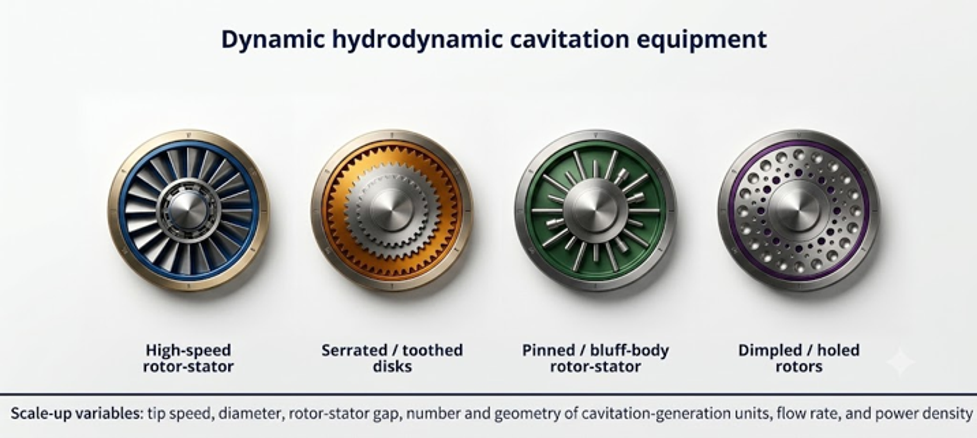
Figure 5.1. Principal dynamic hydrodynamic cavitation device families [32].
A dynamic device should not be sized by rotational speed alone. Machines operating at the same revolutions per minute can exhibit substantially different tip speeds, pressure fields, power demand, and cavitation behavior because rotor diameter, cavity geometry, clearance, flow rate, chamber pressure, and liquid properties differ. The minimum reproducible data set should include rotor and stator drawings, diameter, axial and radial clearances, number and geometry of repeating features, rotational speed, shaft power or torque, chamber pressure, flow rate, temperature, gas condition, and pressure tap locations.
5.1 Speed, tip velocity, and rotational Reynolds number
Rotational speed in revolutions per second is:
and angular velocity is:
For rotor diameter , tip speed is:
A rotational Reynolds number convenient for similar rotors is:
A tip speed Reynolds number can also be used, but the definition must not be changed between data sets. Because the two definitions differ by a factor of , an unlabelled rotational Reynolds number can cause a substantial comparison error.
A rotor based cavitation number is:
where is a defined bulk or chamber absolute pressure. Equation (5.5) is an operating index. The local pressure in a cavity, trailing wake, stator opening, or rotor stator gap depends on the feature geometry and unsteady interaction. A geometry specific inception coefficient must be obtained experimentally or through validated CFD.
The tip Mach number is:
where is liquid sound speed. The bulk tip Mach number may be small while local pressure waves and vapor cloud collapse remain compressible phenomena. The quantity is useful for screening whether incompressible mechanical flow assumptions are reasonable outside the collapse zone.
5.2 Power number, torque, and motor sizing
The power number is:
where is shaft power transferred to the fluid and mechanical losses included within the selected boundary. Rearrangement gives:
The dependence makes power extremely sensitive to speed and scale. Equation (5.8) is valid only when has been calibrated for the same geometry, clearance, flow coefficient, Reynolds number region, chamber pressure, gas fraction, and rheology. Extrapolation through cavitation inception can be inaccurate because vapor changes torque and flow structure.
Shaft torque is:
The motor should be selected from the maximum required torque and power over start up, normal operation, maximum viscosity, maximum solids, cleaning, and upset conditions. A variable frequency drive must satisfy both continuous current and low speed cooling requirements. The shaft, key, coupling, and gearbox should be checked against transient torque and fatigue, not only average power.
Measured electrical power can be converted to estimated shaft power using a calibrated motor and drive efficiency, but direct torque measurement is preferable during development. Bearing, seal, windage, and drive losses under no load should be measured because they can be a substantial fraction of the total in a small laboratory unit.
5.3 Clearance, shear rate, and passage frequency
For a narrow rotor stator gap , the first order Couette shear rate screen is:
where is relative surface velocity. The actual field includes pressure driven flow, turbulence, leakage, entrance and exit jets, and vapor. Equation (5.10) is useful for mechanical and rheological screening but should not be interpreted as the volume averaged treatment shear rate.
If identical rotor features pass a stationary reference point per revolution, the blade or feature passage frequency is:
This frequency can appear in dynamic pressure, vibration, and acoustic spectra. Sidebands or subharmonics can indicate precession, rotating cavitation, cloud shedding, or mechanical modulation. The operating speed should avoid coincidence among passage frequency, shaft frequency, structural natural frequencies, and piping acoustic modes.
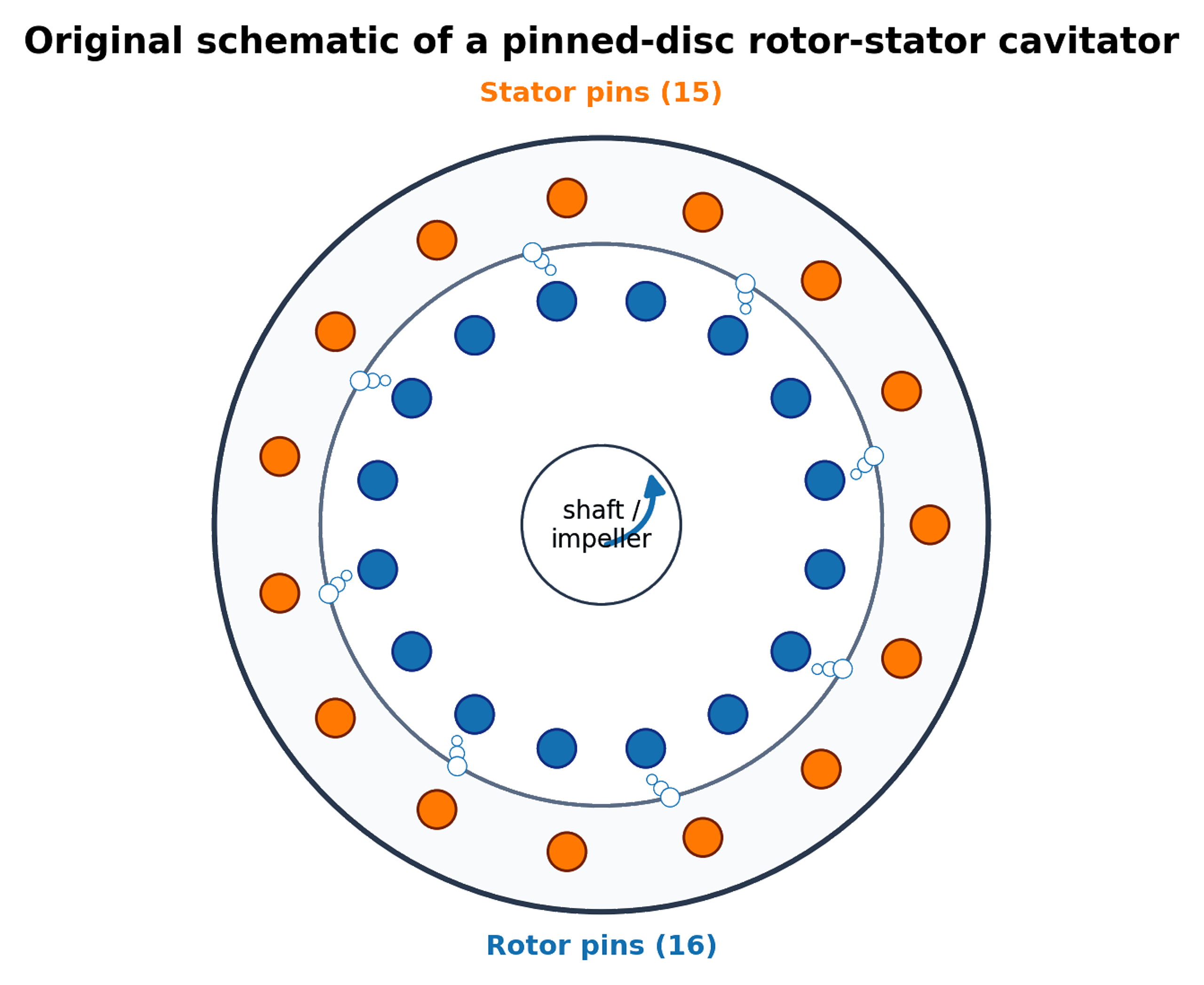
Figure 5.2. Pinned disc rotor and stator geometry and characteristic dimensions used for the worked calculation. [14, 18, 31].
5.4 Flow coefficient, pressure coefficient, and energy density
A dimensionless flow coefficient is:
and a pressure or head coefficient is:
where is defined across the rotating device. Matching , , , , , clearance ratio , and feature ratios gives a more complete similarity basis than matching tip speed alone. In practice, exact simultaneous matching may be impossible, so pilot testing should target the most process sensitive variables.
The mass specific shaft energy for a continuous single pass is:
and an active zone power density can be defined as:
where both the power boundary and active volume must be stated. Dividing total motor input by the entire loop volume and dividing estimated local dissipation by a small gap volume produce different quantities. Both can be useful, but they must not be compared as if they were identical.
5.5 Worked Example 5.1: rotor stator operating point
Design basis. A rotor of diameter m operates in water at 25 °C. The selected speed is 2850 rpm, chamber pressure is 150 kPa absolute, flow is 0.0054 m³/s, gap is 0.8 mm, and the rotor has 12 repeating features. The power number has been calibrated from a measured shaft power near 5.5 kW for this geometry and flow regime. Water properties are kg/m³, Pa·s, and kPa absolute.
Equations (5.1) to (5.3) give s⁻¹, rad/s, and m/s. Equation (5.4) gives . Equation (5.5) gives . The low value indicates a strong rotational pressure scale, but it does not predict the local vapor fraction.
Equation (5.8) gives kW. Equation (5.9) gives torque N·m. The gap shear rate screen from Equation (5.10) is s⁻¹, and Equation (5.11) gives a feature passage frequency of 570 Hz. Equation (5.14) gives a single pass shaft energy of approximately 1022 J/kg. The flow coefficient is .
Table 5.1. Worked Example 5.1 results.
| Quantity | Result | Interpretation |
|---|---|---|
| Rotational speed | 2850 rpm; 47.5 s⁻¹ | Speed must be paired with rotor diameter |
| Tip speed | 28.35 m/s | Governs the selected rotational pressure scale |
| Rotational Reynolds number | Based on | |
| Rotor cavitation number | 0.366 | Uses chamber pressure and tip speed; geometry specific calibration still required |
| Calibrated power number | 0.208 | Applicable only to the tested geometry and regime |
| Shaft power | 5.50 kW | Excludes motor and drive losses unless calibrated otherwise |
| Shaft torque | 18.4 N·m | Basis for coupling and shaft checks, with service factor |
| Gap shear rate screen | s⁻¹ | Couette estimate, not a resolved local field |
| Passage frequency | 570 Hz | Compare with vibration and acoustic spectra |
| Flow coefficient | 0.0166 | Required for similarity comparisons |
| Single pass shaft energy | 1.02 kJ/kg | Relates energy to continuous throughput |
Using the same calibrated without changing geometry or flow regime gives approximately 1.25 kW at 1740 rpm and 2.86 kW at 2290 rpm. The cubic speed dependence is shown in Figure 5.3. These predictions should be checked against measured torque because can change with flow coefficient, clearance, vapor fraction, and rheology.
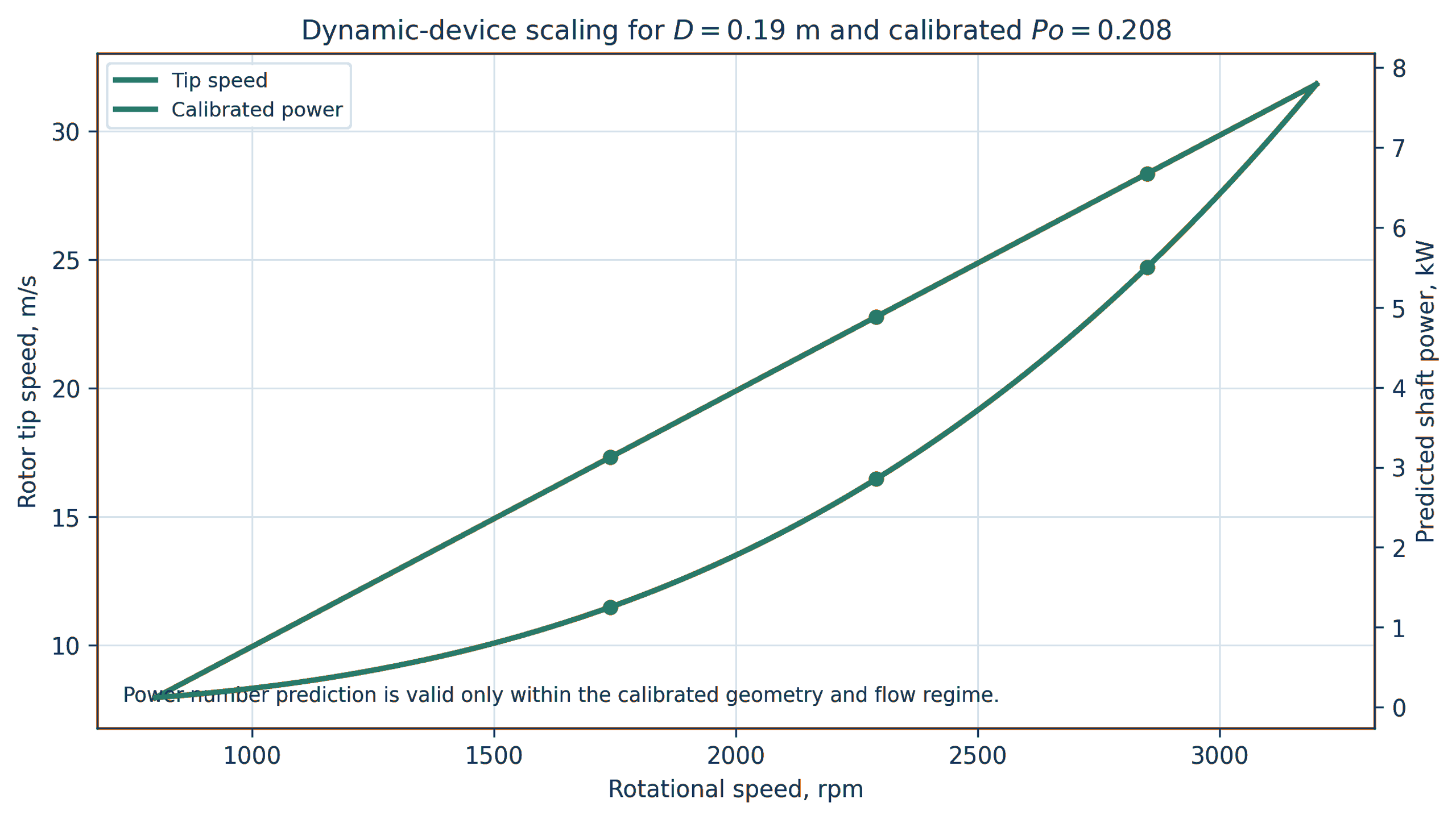
Figure 5.3. Tip speed and shaft power versus speed for Worked Example 5.1 using D_r = 0.19 m and calibrated Po = 0.208. Calculation. Power number extrapolation is valid only within the calibrated geometry and flow regime [32].
5.6 Clearance budget and mechanical tolerance
A small clearance can increase velocity gradients and rotor stator interaction, but it creates a mechanical tolerance problem. The minimum running gap must exceed the combined effects of rotor and stator manufacturing tolerance, shaft runout, bearing clearance, assembly eccentricity, rotor deflection, pressure deformation, thermal expansion, transient vibration, and allowable wear. A practical clearance budget can be written:
where every term is a one sided radial or axial allowance defined for the actual stack up. Statistical tolerance methods may be used for independent manufacturing variables, but worst case combinations are appropriate where rotor contact has severe consequences.
Thermal growth must be calculated for the rotor, shaft, housing, and stator using their temperatures and coefficients of thermal expansion. The rotor can heat faster than the housing during start up, while a cold clean in place rinse can reverse the gradient. The gap should be verified at assembly temperature, normal operation, maximum process temperature, and cleaning transitions.
5.7 Rotor stress, balance, and critical speed
For a thin free ring, a first order circumferential stress screen is:
where is rotor material density. Real disks, pins, holes, cavities, keys, hubs, and welds require a detailed rotating stress solution. Stress concentration, low and high cycle fatigue, corrosion fatigue, residual stress, overspeed, and loss of material by erosion must be included. Finite element analysis should use the minimum remaining section after the specified inspection interval.
Rotors should be dynamically balanced in the final assembly condition, including pins, fasteners, coatings, and replaceable elements. Cavitation erosion can change balance during service. Vibration monitoring should include shaft frequency, feature passage frequency, bearing frequencies, and broadband cavitation content. A speed sweep should identify structural resonances before prolonged cavitating operation.
5.8 Cleanability, disassembly, and wear components
A device designed for viscous, fibrous, food, pharmaceutical, or fouling service requires access to the active geometry. Replaceable rotors, stator rings, wear plates, and collapse inserts can reduce lifecycle cost and prevent the pressure boundary from becoming a sacrificial surface. Disassembly should preserve alignment and repeatable clearance. Crevices, blind holes, gasket intrusion, and trapped pressure must be eliminated or controlled.
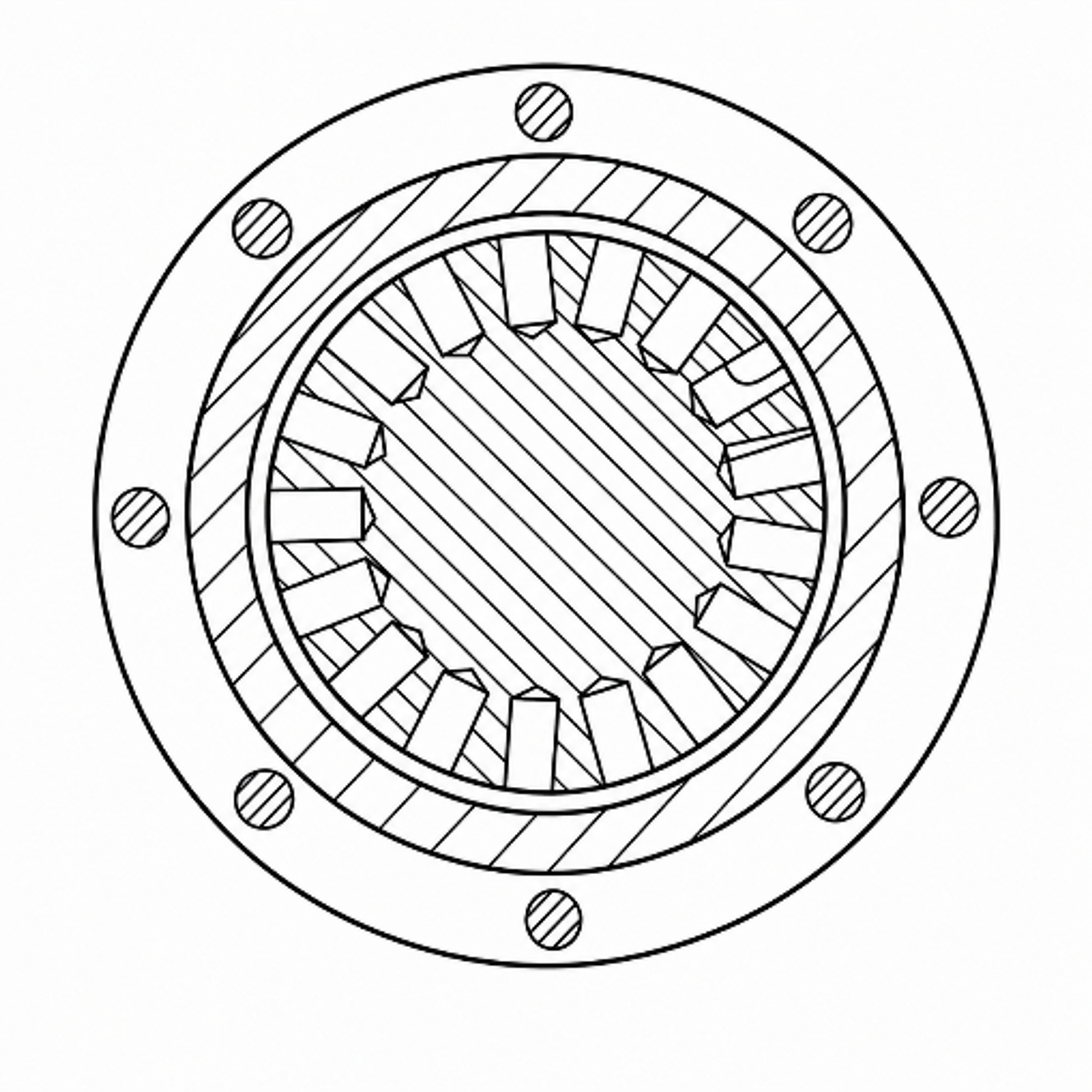
Figure 5.4. Holed rotor controlled cavitation device arranged for disassembly and cleaning. [18].
5.9 Dynamic device calculation workflow
The recommended workflow is:
-
Define flow, pressure, temperature, rheology, gas, solids, product objective, and hygienic requirements.
-
Select rotor diameter, feature family, number of features, chamber volume, and preliminary clearance.
-
Calculate tip speed, , , , feature passage frequency, and mechanical clearance budget.
-
Obtain a non cavitating torque and flow map over speed and flow.
-
Identify cavitation inception using pressure, acoustic, vibration, visualization, and power changes.
-
Fit and any geometry specific inception or pressure coefficient within the validated region.
-
Measure product response and temperature at the same operating points.
-
Complete rotor stress, shaft, bearing, seal, pressure boundary, fatigue, overspeed, and balance calculations.
-
Run an endurance test with dimensional inspection, vibration trending, and contaminant analysis.
-
Scale by a defined similarity set or preserve the validated rotor module through parallel scale out.
Table 5.2. Required dynamic device calculation outputs.
| Discipline | Required output |
|---|---|
| Hydraulics | Flow pressure map, chamber absolute pressure, inlet and outlet losses, residence time |
| Rotation | Speed range, tip speed, , , , , passage frequency |
| Power | No load loss, shaft torque, , electrical input, specific energy, heat balance |
| Mechanical | Rotor and shaft stress, overspeed margin, critical speeds, balance grade, clearance stack up |
| Tribology | Seal face condition, bearing load, lubricant isolation, galling and rub assessment |
| Process | Product response surface, temperature history, gas condition, pass or staging dependence |
| Integrity | Erosion map, minimum remaining thickness, vibration trend, metal contamination |
| Sanitary design | Surface finish, drainability, clean in place coverage, disassembly validation |