
Technical publication
Back to publications
Reactors & equipment
Calculations of Hydrodynamic Cavitation Devices
okozyuk.com
Published
Read complete publication for whole-document Find and printing. Browser Find and native printing on this reader include only loaded content.
2 Calculation Basis and Design Workflow
This section defines the consolidated calculation and reporting framework used throughout the article. Subsequent sections apply consistent definitions for absolute pressure, cavitation number, hydraulic and electrical energy, residence time, exposure, uncertainty, and scale translation. Equations are repeated only when a specialized derivation or interpretation is required.
2.1 Required design inputs
The calculation begins with the process duty rather than a preferred device configuration. The minimum data set in Table 2.1 separates properties required for hydraulic sizing from variables required for process validation and mechanical design. A single nominal density and viscosity are insufficient when temperature, composition, gas content, or solids loading varies during operation.
Table 2.1. Minimum design inputs for hydrodynamic cavitation calculations.
| Category | Required information | Calculation affected |
|---|---|---|
| Capacity | Minimum, normal, and maximum volumetric or mass flow; batch and loop volume; required turndown | Flow area, velocity, pump or motor size, residence time, parallel modules |
| Pressure | Suction pressure, upstream pressure, downstream pressure, backpressure, allowable pressure drop, relief set pressure | Local pressure screen, cavitation number, pressure boundary, pump duty |
| Temperature | Minimum, normal, and maximum temperature; allowable temperature rise | Density, viscosity, vapor pressure, seal compatibility, thermal growth |
| Liquid properties | Density, dynamic viscosity, vapor pressure, speed of sound, surface tension where relevant | Reynolds number, cavitation inception, collapse, pressure transients |
| Multiphase properties | Gas content, gas solubility, solids loading and size, dispersed phase fraction, rheology | Nucleation, blockage, wear, phase separation, model selection |
| Product objective | Reaction conversion, droplet or particle distribution, cell disruption, contaminant removal, heating, gas dispersion | Required exposure, passes, energy, sampling and acceptance limits |
| Geometry constraints | Pipe size, available length, cleanability, minimum passage, allowable rotor diameter and clearance | Device family, throat or hole size, diffuser length, rotor layout |
| Materials environment | pH, chloride, oxidants, solvents, acids, caustic, abrasive solids, hygiene requirements | Alloy, coating, elastomer, corrosion allowance, surface finish |
| Utilities | Electrical supply, pump curve, cooling duty, nitrogen or gas injection, instrumentation | Installed power, control strategy, heat exchanger and interlocks |
| Reliability | Inspection interval, permitted metal contamination, spare strategy, acceptable downtime | Replaceable inserts, erosion allowance, monitoring and lifecycle cost |
Material properties should be evaluated at each relevant operating state. For water like liquids, vapor pressure changes rapidly with temperature and can dominate the cavitation margin. For viscous oils, concentrated suspensions, polymer solutions, and emulsions, apparent viscosity may be shear dependent and pressure losses outside the cavitation element may no longer be negligible. The design envelope should therefore include startup, shutdown, cleaning, upset, and maximum temperature conditions rather than only the nominal process state.
2.2 Pressure references and measurement stations
Pressure must be placed on an absolute basis before it is compared with vapor pressure:
where is absolute pressure, is gauge pressure, and is local atmospheric pressure. A vacuum gauge reading requires the corresponding sign convention. Barometric variation is usually small relative to a high pressure device, but it can be important in low pressure systems and suction calculations.
The instrumentation arrangement should establish reproducible pressure stations upstream and downstream of the cavitation element while recognizing that these taps do not normally measure the local minimum pressure. Rapid pressure pulsation may require high frequency transducers in addition to conventional process transmitters. Tap diameter, distance from the element, pipe diameter, straight length, tubing volume, transducer range, and sampling frequency should be documented [2,4–6].
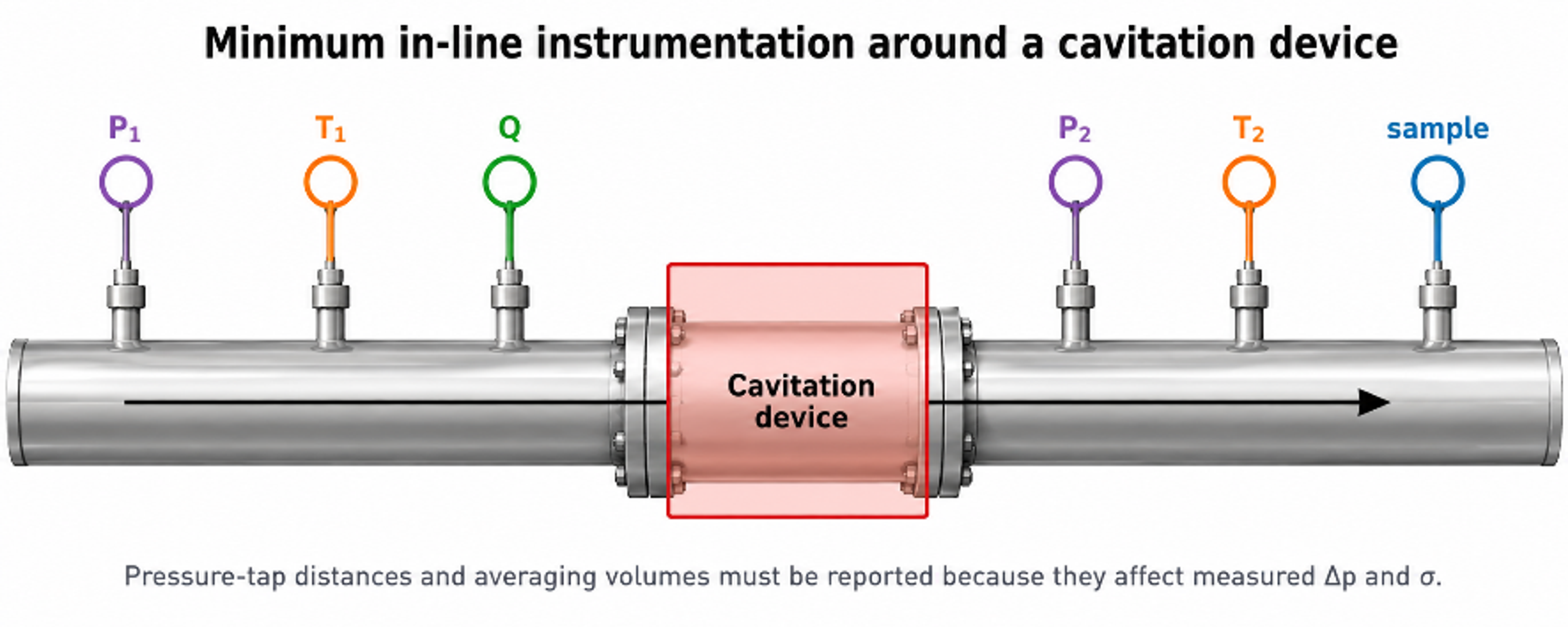
Figure 2.1. Minimum instrumentation around the flow through cavitation element [32].
For an incompressible stream, volumetric flow and mass flow are:
where is volumetric flow rate, is cross sectional area, is mean velocity, is mass flow rate, and is density.
A practical mechanical energy balance between stations 1 and 2 is:
where is gravitational acceleration, is elevation, is head added by a pump within the control volume, is irreversible head loss, and is the kinetic energy correction factor. For a short horizontal element with no pump between the taps, the elevation and pump terms are omitted. The equation remains an averaged energy balance; it does not resolve the local pressure depression inside a separated, swirling, or transient flow.
Figure 2.2 illustrates the importance of local pressure history. A sharp restriction may generate a short, steep pressure minimum followed by highly dissipative recovery, whereas a well designed Venturi can provide a longer low pressure region with more controlled recovery. These conceptual profiles do not replace calibrated pressure measurements, but they inform throat length, diffuser geometry, and the placement of downstream surfaces.
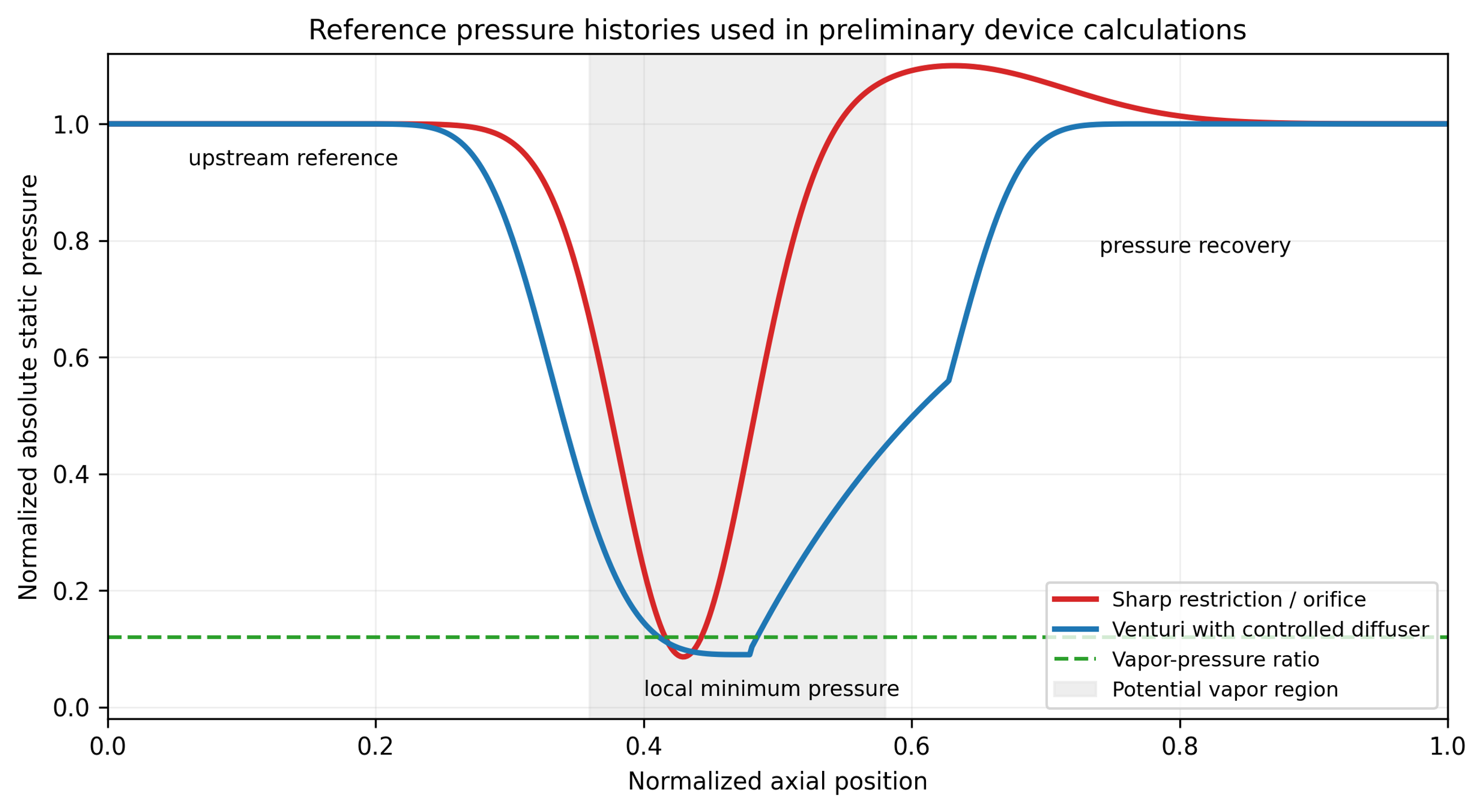
Figure 2.2. Conceptual absolute pressure histories for a sharp restriction and a Venturi with controlled recovery [32].
2.3 Dimensionless groups
The Reynolds number based on a stated characteristic length and velocity is:
where is dynamic viscosity. The Euler number, written here as a pressure loss coefficient, is
The Weber number is:
where is surface or interfacial tension. For two phase dispersions, the relevant interfacial tension and characteristic droplet or jet dimension must be specified.
The general cavitation number is:
where and are explicitly defined reference pressure and velocity, and is vapor pressure at the local temperature. Published values are not comparable unless the reference stations and velocity definition are the same. For an orifice study, may be downstream pressure and the jet velocity; for a Venturi it may be throat or downstream pressure and throat velocity; for a rotor it may be chamber pressure and rotor tip speed [2–6].
A pressure drop cavitation index frequently used in flow through equipment is:
where and are stated upstream and downstream absolute pressures. This form is convenient because the denominator is measured pressure drop, but it still does not resolve the local minimum pressure. It should be treated as an operating index tied to the test geometry.
The preliminary vapor formation criterion is:
and a preliminary collapse criterion is:
where is the calculated or modeled local minimum pressure and is the pressure in the intended recovery region. Inception can occur above equilibrium vapor pressure because of gas nuclei and unsteady pressure, while a cavity can persist after the mean pressure has recovered. Equations (2.10) and (2.11) are therefore screening conditions rather than exact phase boundary laws [1–3].
Table 2.2. Interpretation and limitations of principal similarity groups.
| Group | Principal comparison | Must be defined | Important limitation |
|---|---|---|---|
| Inertia relative to viscosity | Velocity and length scale | Does not preserve nuclei, vapor fraction, collapse location, or residence time | |
| Pressure change relative to dynamic pressure | Pressure stations and velocity | Can global pressure loss match while local pressure fields differ | |
| Inertia relative to surface or interfacial tension | Interface and length scale | Relevant to breakup, but not sufficient for recoalescence or chemistry | |
| Pressure margin above vapor pressure | Absolute pressure and velocity reference | Definition varies by device; one value cannot describe a full pressure history | |
| Downstream pressure margin normalized by measured loss | Upstream and downstream taps | Does not directly measure vena contracta, core, or blade passage pressure | |
| Unsteady frequency relative to convection | Characteristic frequency and length | Frequency similarity does not guarantee the same vapor cloud amplitude | |
| Shaft power is relative to rotational inertial scale | Shaft power, speed, rotor diameter | Geometry, clearance, flow coefficient, and gas fraction must remain comparable |
2.4 Hydraulic power, electrical power, residence time, and dose
The hydraulic power associated with a measured pressure drop is:
For a pump driven static device, the approximate electrical input assigned to the cavitation duty is:
where is pump efficiency, is motor efficiency, and represents drive or transmission efficiency. For a complete system assessment, auxiliary loads, recirculation losses, cooling, and control equipment should be included. Measured electrical power is preferred over nameplate power.
The single pass hydraulic specific energy is:
and the corresponding mass specific electrical energy over a treatment interval is:
A short device volume has nominal residence time:
For a well mixed recirculation tank of volume , the nominal number of loop turnovers during time is:
This turnover count does not guarantee that each fluid element has passed through the device exactly times. A real loop has a residence time distribution, short circuiting, dead volume, and mixing effects. For comparison of process results, the report should include the tank volume, external piping volume, device hold up, flow history, sample location, and whether the product is withdrawn continuously or only after recirculation [2–5].
2.5 Collapse time and placement of the recovery zone
A useful inertial estimate for the collapse time of an initially spherical vapor cavity of radius under a constant pressure difference is the Rayleigh expression:
where is the recovered far field pressure. The corresponding convective distance is:
where is a representative convection velocity. These equations do not include dissolved gas, thermal effects, non spherical collapse, cloud interaction, or wall proximity, but they help place a replaceable collapse chamber, avoid a vulnerable weld, and estimate whether a long low pressure zone will carry cavities beyond the intended active region [1,2].
For example, a water vapor cavity with mm exposed to a recovered pressure difference of 200 kPa has an inertial collapse time of approximately 32 microseconds. At a convection velocity of 12 m/s, the corresponding distance is approximately 0.38 mm. Real clouds can persist much farther because of gas content, collective shielding, repeated growth, and spatially distributed pressure recovery. The calculation is therefore a lower order location screen, not an erosion life prediction.
2.6 Uncertainty and model hierarchy
For a result with independent input uncertainties, the first order combined standard uncertainty is:
where is the standard uncertainty of input . Correlated variables require covariance terms. A design calculation should separate measurement uncertainty from model form uncertainty. The latter includes uncertainty in discharge coefficient, pressure recovery coefficient, vortex core model, power number, two phase closure, and the relationship between hydraulic state and product response.
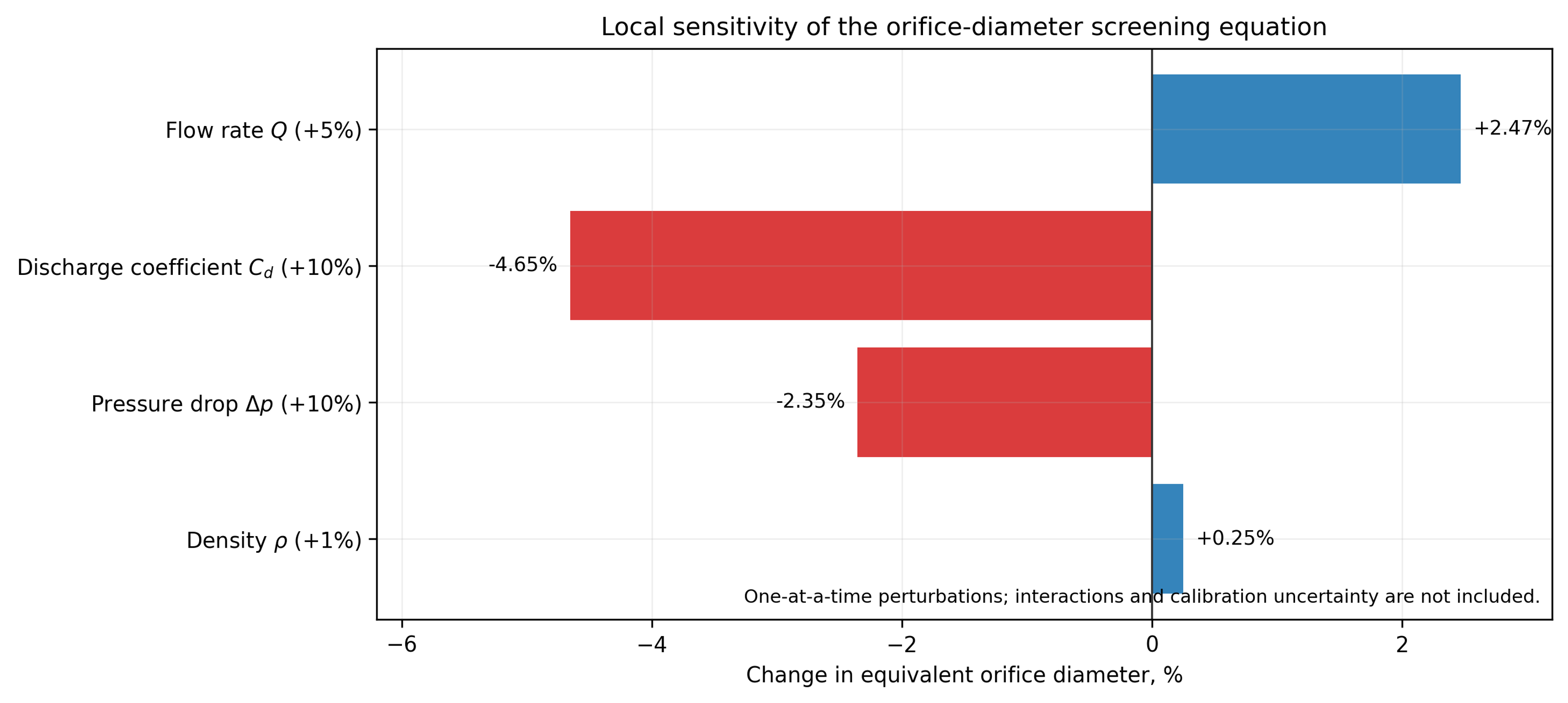
Figure 2.3. Local sensitivity of the preliminary orifice diameter equation to representative input perturbations. The result illustrates parameter sensitivity and does not include model form or interaction uncertainty [32].
Table 2.3. Recommended model fidelity by design question.
| Design question | Minimum method | Escalation trigger | Validation evidence |
|---|---|---|---|
| Required open area and pump pressure | One dimensional continuity and calibrated loss coefficient | Non Newtonian flow, gas fraction, severe choking, uncertain | Flow pressure curve at operating temperature |
| Local cavitation inception | Pressure screen plus calibrated inception map | Geometry has separation, vortex core, multiple jets, or transient rotor interaction | Visualization, acoustic signature, high speed pressure, or validated CFD |
| Cavity extent and collapse location | Empirical map or two phase CFD | Erosion sensitive surface, reaction selectivity, scale change | Imaging, erosion coupons, hydrophone or pressure mapping |
| Rotor power | Calibrated , torque measurement, motor map | Clearance, flow coefficient, gas fraction, or rheology changes | Shaft torque and electrical power over full operating map |
| Product performance | Empirical response surface | Composition, temperature, or scale differs from test | Replicated pilot trials and product analysis |
| Erosion life | Comparative material tests and pilot inserts | Long service interval, toxic metal limit, corrosive abrasive fluid | Periodic mass/thickness loss and contaminant analysis |
The dominant uncertainty is often not the pressure measurement itself but the assumption that a hydraulic index predicts the required process response. A pilot program should therefore map hydraulic variables and product attributes concurrently. A model should be accepted only within the region where measured flow, pressure, power, temperature, cavity signature, process response, and equipment integrity remain mutually consistent.