
Technical publication
Back to publications
Reactors & equipment
Calculations of Hydrodynamic Cavitation Devices
okozyuk.com
Published
Read complete publication for whole-document Find and printing. Browser Find and native printing on this reader include only loaded content.
1 Introduction
Hydrodynamic cavitation occurs when the pressure history experienced by a flowing liquid permits preexisting nuclei to expand into vapor filled or gas vapor cavities and subsequently subjects those cavities to sufficiently rapid pressure recovery. In static devices, this pressure history is produced by acceleration through a fixed restriction, flow separation, jet expansion, wake formation, or swirl. In dynamic devices, rotors, rotor stator clearances, pin arrays, cavities, grooves, or moving blades repeatedly create regions of reduced pressure followed by recovery. Although the governing physical principles are common, calculation procedures cannot be transferred directly among device families [1–7].
Three recurring design errors should be avoided. First, cavitation should not be treated as a binary condition. A local pressure below vapor pressure indicates the potential for vapor formation, but it does not define cavity population, cloud structure, residence time, collapse intensity, process response, or erosion rate. Second, the measured upstream to downstream pressure difference should not be interpreted as the local minimum pressure. A wall tap averages pressure over a finite region and may not detect conditions at a vena contracta, separated shear layer, vortex core, rotor cavity, or transient blade passage. Third, no single dimensionless group constitutes a complete scale up criterion. Reynolds number, Euler number, Weber number, cavitation number, flow coefficient, power number, and residence time each preserve only part of the coupled system behavior [3–12].
A defensible design calculation is therefore organized into four levels. The first level is a transparent one dimensional or lumped parameter screening model that establishes required flow area, mean velocity, pressure drop, power, nominal residence time, pressure boundary load, and a preliminary cavitation regime. The second level applies calibrated discharge, loss, recovery, power, or circulation coefficients obtained from water testing or a geometrically similar device. The third level uses validated computational fluid dynamics when local pressure, vapor fraction, recirculation, or rotor stator interaction cannot be represented adequately by a lumped model. The fourth level is pilot confirmation in the actual process fluid because viscosity, vapor pressure, dissolved gas, suspended solids, non Newtonian behavior, interfacial tension, reaction kinetics, and contamination limits can shift the useful operating window [5, 7, 10–15].
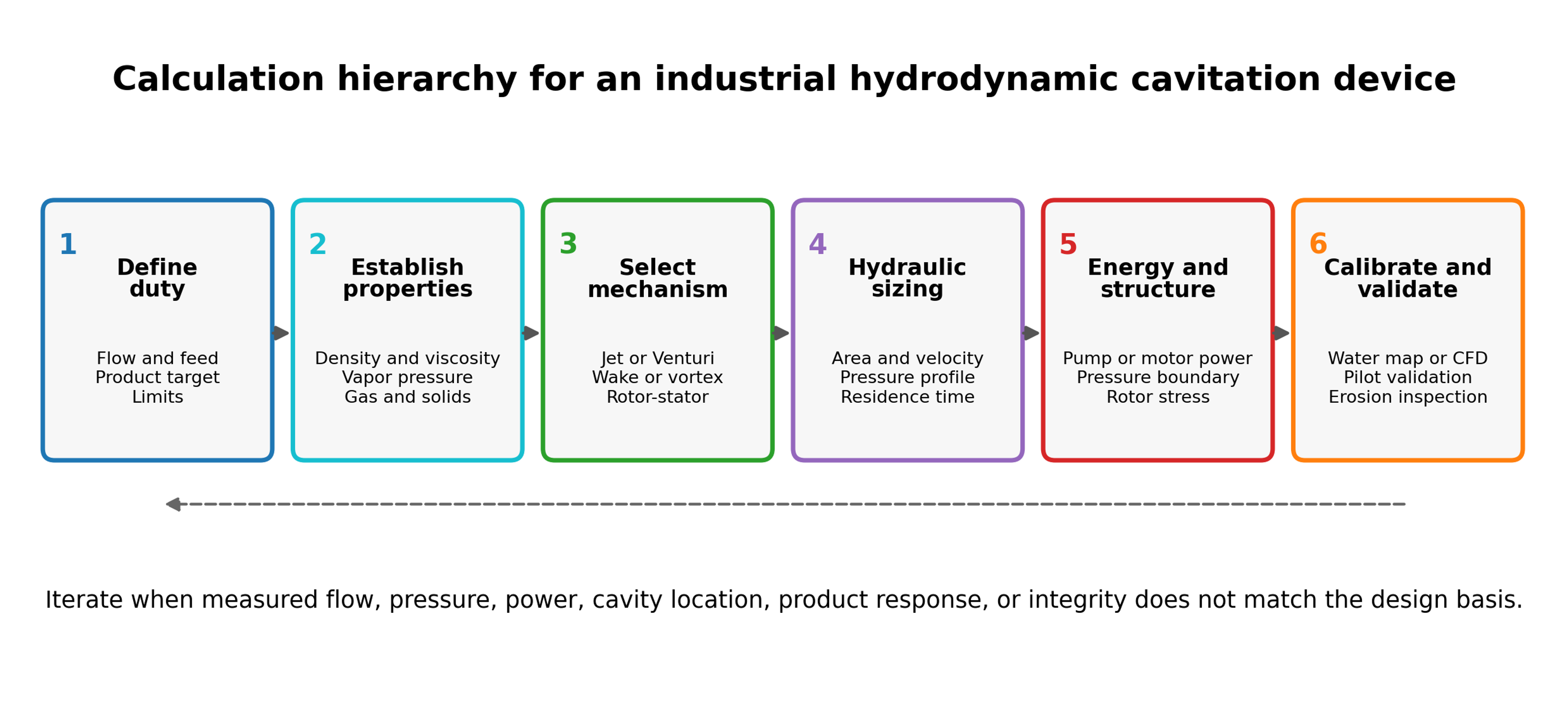
Figure 1.1. Calculation hierarchy for an industrial hydrodynamic cavitation device [32].
The objective of the calculation is not to predict every individual bubble. It is to establish a traceable design basis and identify the assumptions that require calibration or experimental confirmation. The calculation record should answer the following questions:
-
What flow rate and feed property envelope must be processed?
-
Which absolute pressure is expected at the active cavitation location?
-
Where will cavities grow, and where should they collapse?
-
What pump or motor power is required at the selected operating point?
-
What exposure, residence time, number of stages, or number of passes is delivered?
-
Which part is the pressure boundary, which part is a wear insert, and which parts must be hygienic or chemically inert?
-
How will the hydraulic state, product response, erosion, contamination, and uncertainty be verified?
This article uses SI units unless stated otherwise. All pressures used in vapor pressure and cavitation number calculations are absolute. Gauge pressure is used only after explicit conversion. Correlations should not be transferred between geometries without a stated technical basis, and calculated values should be reported with sufficient significant figures for reproducibility without implying unrealistic precision.