
Technical publication
Back to publications
Industrial applications
Sonochemical Effect Induced by Hydrodynamic Cavitation
okozyuk.com
Published
Read complete publication for whole-document Find and printing. Browser Find and native printing on this reader include only loaded content.
11 Energy Partition, Reactor Integration, and Scale Up
Only a fraction of the initial pump or shaft energy is ultimately converted into chemical products. The majority of input energy is dissipated through various physical and chemical pathways, including:
-
Fluid dynamics: Ordinary turbulence, viscous losses, and large scale fluid circulation
-
Thermodynamic and acoustic effects: Thermal heating and pressure waves
-
Cavitation phenomena: Bubble rebound, microjets, and material erosion
Didenko and Suslick [26] quantified the energy partition among photons, radicals, ions, and mechanical outputs for single bubble acoustic cavitation, demonstrating that chemical energy conversion represents a minor yet measurable branch.
Because hydrodynamic reactors introduce significant fluid circulation and permanent pressure losses, precise definition of the system boundary remains essential for accurate performance evaluation and scale up.
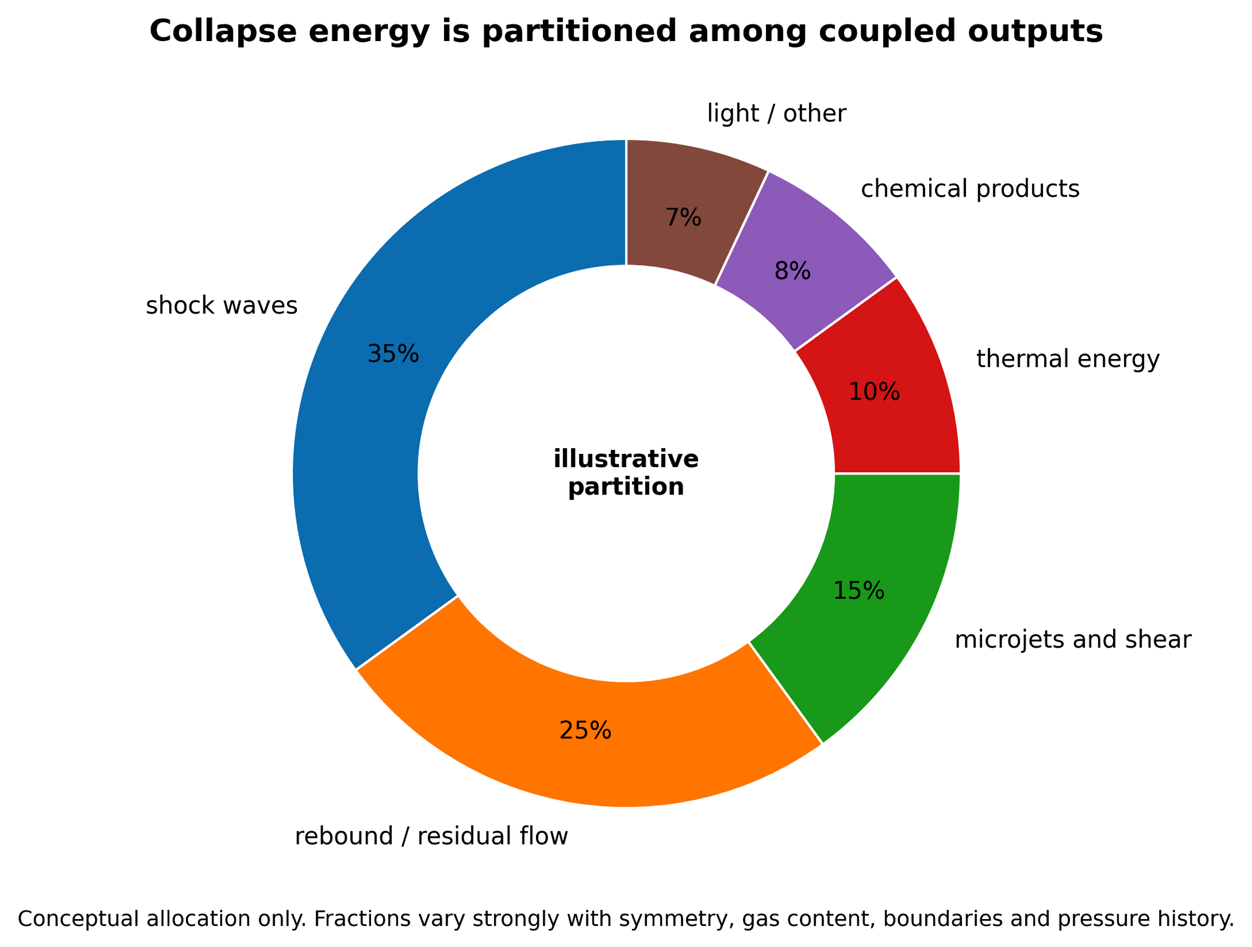
Figure 11.1. Illustrative partition of collapse energy among shock waves, rebound, microjets and shear, thermal energy, chemical products, and light [81].
Chemical energy efficiency () can be formally quantified as:
where is moles of chemical product j, is a selected Gibbs energy value for its formation or useful reaction, and is the stated energy boundary.
For repeated pass treatment with a constant per pass removal fraction , a simple model is:
where N is the number of passes. The model is useful for early design but fails when fluid properties, intermediates, or radical demand change with conversion.
A continuous reactor with residence time distribution E(t) gives outlet concentration:
for a first order reaction with rate constant k.
For geometrically similar devices, a pressure drop similarity criterion can be written:
where Eu is the Euler number. Maintaining Eu alone does not guarantee similar cavitation chemistry because nuclei, Reynolds number, residence time, vapor pressure, and gas content may differ.
A useful collapse exposure density is:
where is the number of chemically active collapse events, is mean energy per active collapse, and is treated volume. is conceptual because the two microscopic quantities are difficult to measure, but it identifies the scale up target more directly than void fraction.
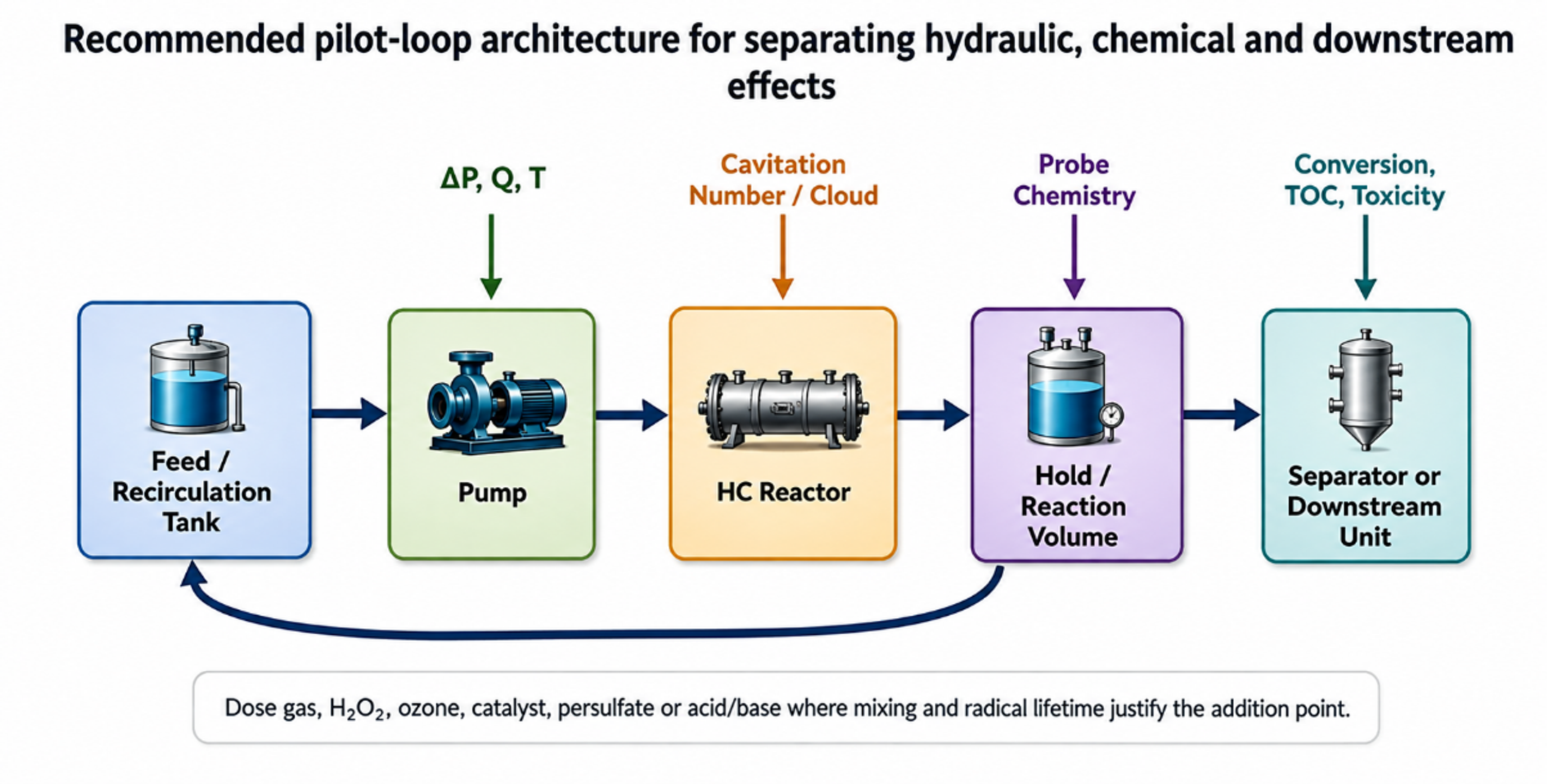
Figure 11.2. Recommended pilot loop architecture for separating hydraulic, chemical, and downstream effects [81].
The pilot loop in Figure 11.2 places pressure and temperature measurements immediately around the cavitation device, includes gas conditioning and sampling, and provides a downstream hold or reaction volume. This separation is important because radicals are generated in the cavitation zone but longer lived species can continue reacting downstream. A heat exchanger controls the temperature history so that chemical improvements are not confused with simple warming. A separator or quench point permits mass balance on volatile compounds, solids, or phases.
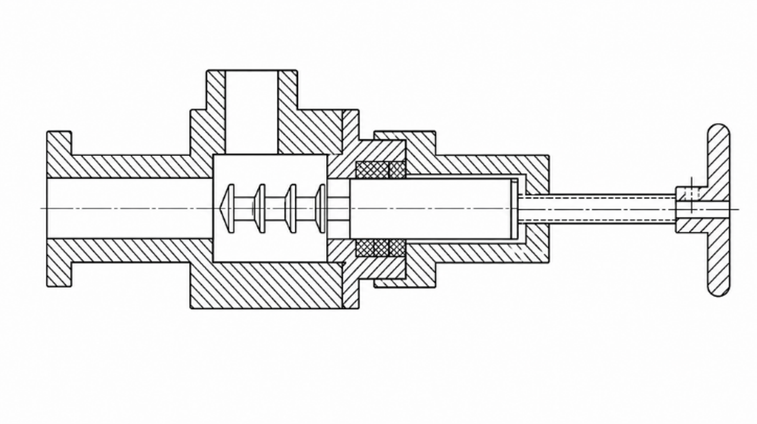
Figure 11.3. Multistage controlled flow hydrodynamic cavitation device with repeated flow passages and recovery regions. [17].
Multistage controlled flow devices, such as the arrangement shown in Figure 11.3, are intended to create repeated cavitation events while maintaining continuous throughput [17]. Staging can distribute the total pressure drop, provide controlled recovery between elements, and improve exposure uniformity. It can also increase cumulative erosion and pumping demand. The correct number of stages is determined by incremental chemical yield, not by the largest feasible pressure drop.
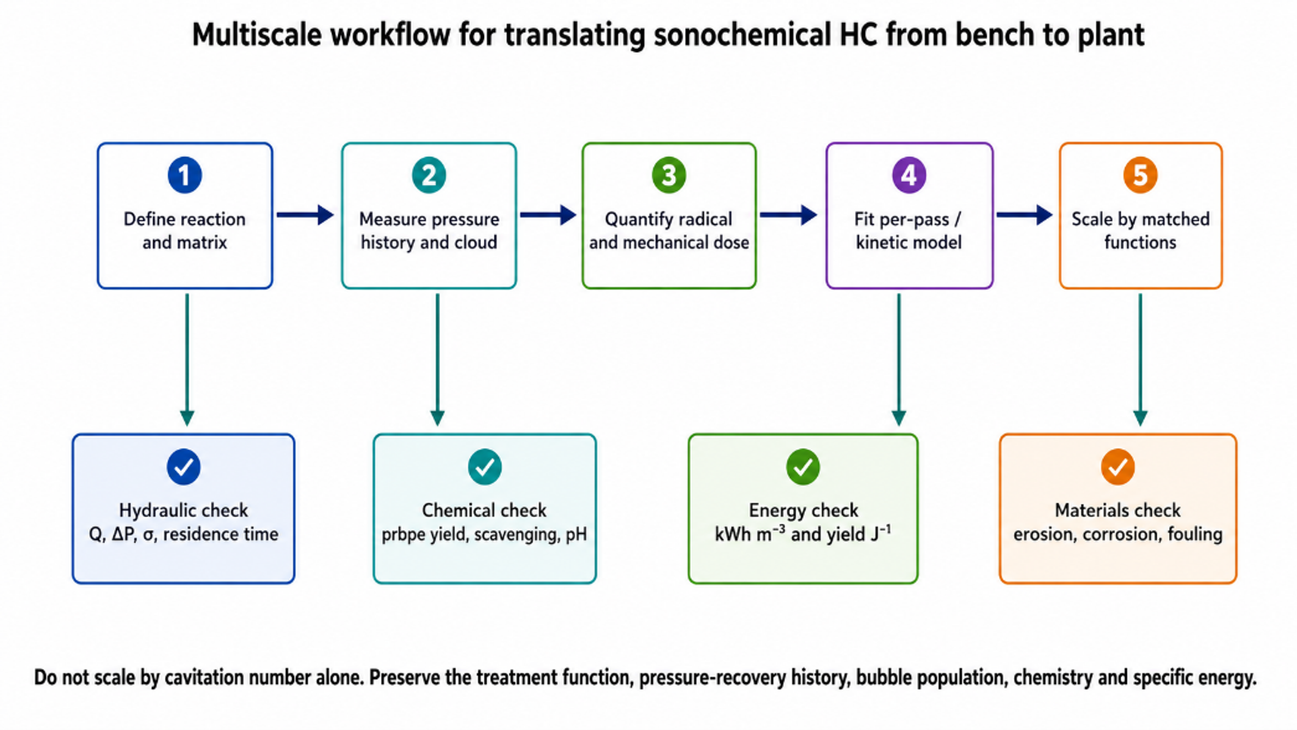
Figure 11.4. Multiscale workflow for translating sonochemical hydrodynamic cavitation from bench to plant [81].
Table 11.1. Scale up variables that should be preserved or explicitly reoptimized
| Category | Variable | Why it matters | Scale up approach |
|---|---|---|---|
| Hydraulic | Pressure ratio and recovery profile | Sets bubble growth and collapse history | Use pressure taps and validated CFD, not pump discharge pressure alone |
| Hydraulic | Velocity and Reynolds number | Controls turbulence, separation, and nuclei transport | Maintain relevant range or characterize deviation |
| Bubble population | Nuclei concentration and dissolved gas | Sets active bubble number and cushioning | Condition gas and characterize feed |
| Thermodynamic | Temperature and vapor pressure | Controls vapor loading and physical properties | Use heat removal and matched temperature history |
| Chemical | Probe or target concentration | Changes scavenging, partition, and oxidant demand | Scale at matched composition and conversion target |
| Exposure | Pass number or residence time distribution | Determines cumulative treatment | Use tracer tests and per pass sampling |
| Energy | Hydraulic and electrical specific energy | Determines economics and comparison | Report both device and whole system boundaries |
| Materials | Wall stress and erosion rate | Can contaminate product and limit life | Coupons, inspection, replaceable liners |
| Control | Backpressure and gas holdup | Moves cloud and changes collapse location | Closed loop pressure and gas control |
| Downstream | Hold time, separation, and quench | Long lived chemistry may continue after device | Preserve reaction and separation sequence |
Table 11.2. Minimum measurement package for pilot and industrial evaluation
| Measurement | Preferred location | Purpose | Common error if omitted |
|---|---|---|---|
| Static pressure | Immediately upstream, throat where possible, and downstream | Define pressure history and Δp | Using pump rating as device pressure |
| Flow rate | Calibrated line section | Hydraulic power and pass count | Ignoring gas or slurry effect on meter |
| Electrical power | Motor drive or power analyzer | Plant relevant energy | Using nameplate power |
| Temperature | Feed, device outlet, tank | Vapor pressure and thermal control | Attributing thermal reaction to cavitation |
| Dissolved gas/oxygen | Feed and return | Reproducibility and gas chemistry | Uncontrolled air entrainment |
| Chemical dosimeter | Feed and immediate outlet | Per pass radical activity | Only measuring after long tank residence |
| Target and products | Time series and outlet | Conversion, selectivity, mineralization | Using color or parent loss alone |
| Cavitation structure | Optical window or acoustic sensor | Identify regime and collapse location | Assuming more noise means more chemistry |
| Erosion and metals | Coupons, filters, product | Materials integrity and contamination | Ignoring wear derived catalytic effects |
| Residence time distribution | Tracer test across loop or reactor | Scale up and kinetic interpretation | Treating total tank volume as active reactor volume |