
Technical publication
Back to publications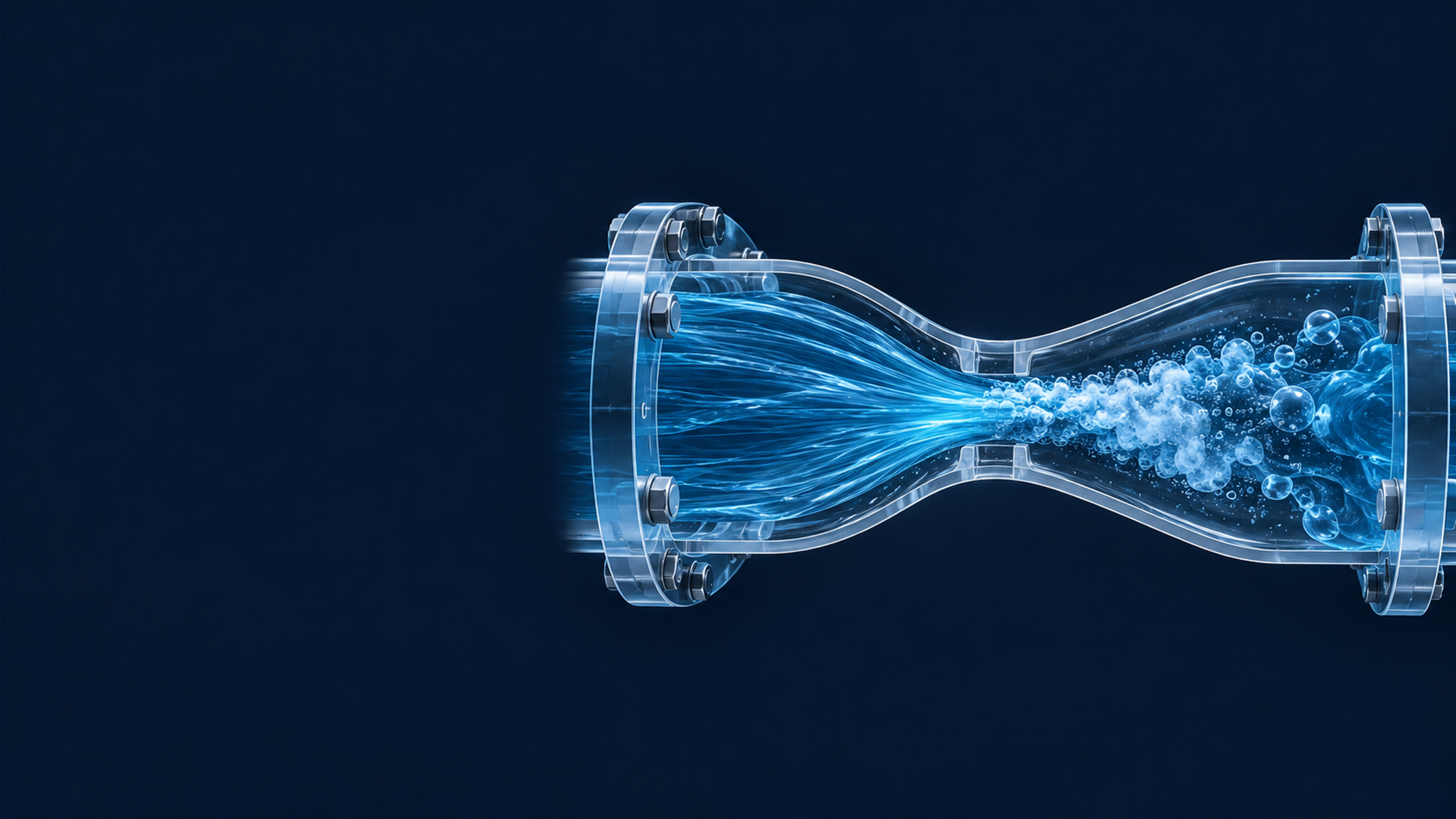
Fundamentals
Physical Basis of Hydrodynamic Cavitation Generation
okozyuk.com
Published
Read complete publication for whole-document Find and printing. Browser Find and native printing on this reader include only loaded content.
2.1 Pressure, Velocity, and Cavitation Inception
For steady incompressible flow through a hydrodynamic cavitation device, conservation of volume gives the volumetric flow rate as:
where denotes the volumetric flow rate, the local cross sectional area, and the area averaged liquid velocity. Consequently, a reduction in flow area increases the mean velocity. Along a streamline, the mechanical energy balance can be expressed as:
where is static pressure, is liquid density, is gravitational acceleration, is elevation, is the kinetic energy correction factor, and is the irreversible head loss. For a short horizontal restriction, the elevation term is generally negligible. Flow acceleration converts static pressure into kinetic energy, whereas separation, turbulence, two phase flow, and downstream mixing dissipate part of the recoverable pressure.
Cavitation inception becomes possible when the local pressure approaches an effective inception pressure. In an ideal pure liquid at a defect free interface, the tensile limit can lie below the equilibrium vapor pressure. Practical process liquids, however, contain microscopic nuclei, dissolved gas, suspended particles, surface roughness, and surfactants, and these features promote inception before the ideal tensile limit is reached. The saturation vapor pressure is therefore a necessary thermodynamic parameter but is not, by itself, sufficient to predict inception. Increasing temperature raises , while increased dissolved gas content generally increases the population of available nuclei.
The cavitation number is the most widely used dimensionless index for characterizing the relation between pressure level and dynamic pressure:
where and denote the selected reference pressure and velocity. A smaller generally corresponds to a greater tendency toward cavitation. Because the definition is not universal, studies may use upstream or downstream pressure and may define velocity at the throat or from a bulk flow estimate. Therefore, a reported value of is interpretable only when the pressure location and velocity definition are specified [1,2,3].
For geometrically similar restrictions, Reynolds, Weber, and Euler numbers provide additional scaling measures:
where is a characteristic hydraulic diameter, is dynamic viscosity, is surface or interfacial tension, and is pressure drop. Reynolds number compares inertial and viscous effects, Weber number compares inertial loading with interfacial tension, and Euler number relates pressure loss to dynamic pressure. These parameters do not uniquely determine the cavity field, but they provide a consistent basis for comparing geometrically related devices and operating scales.