
Technical publication
Back to publications
Reactors & equipment
Hydrodynamic Cavitation in Emulsification and Homogenization
okozyuk.com
Published
Read complete publication for whole-document Find and printing. Browser Find and native printing on this reader include only loaded content.
8 Scale Up, Control, and Industrial Design
8.1 Scale up pathways
Three pathways are used in practice. Geometric scale up increases device size while attempting to preserve relevant similarity parameters. Scale out operates multiple validated modules in parallel. Recirculation uses a smaller device repeatedly until the product reaches its target. Each pathway changes cost, residence time distribution, heat removal, control, and cleaning [19,24–29].
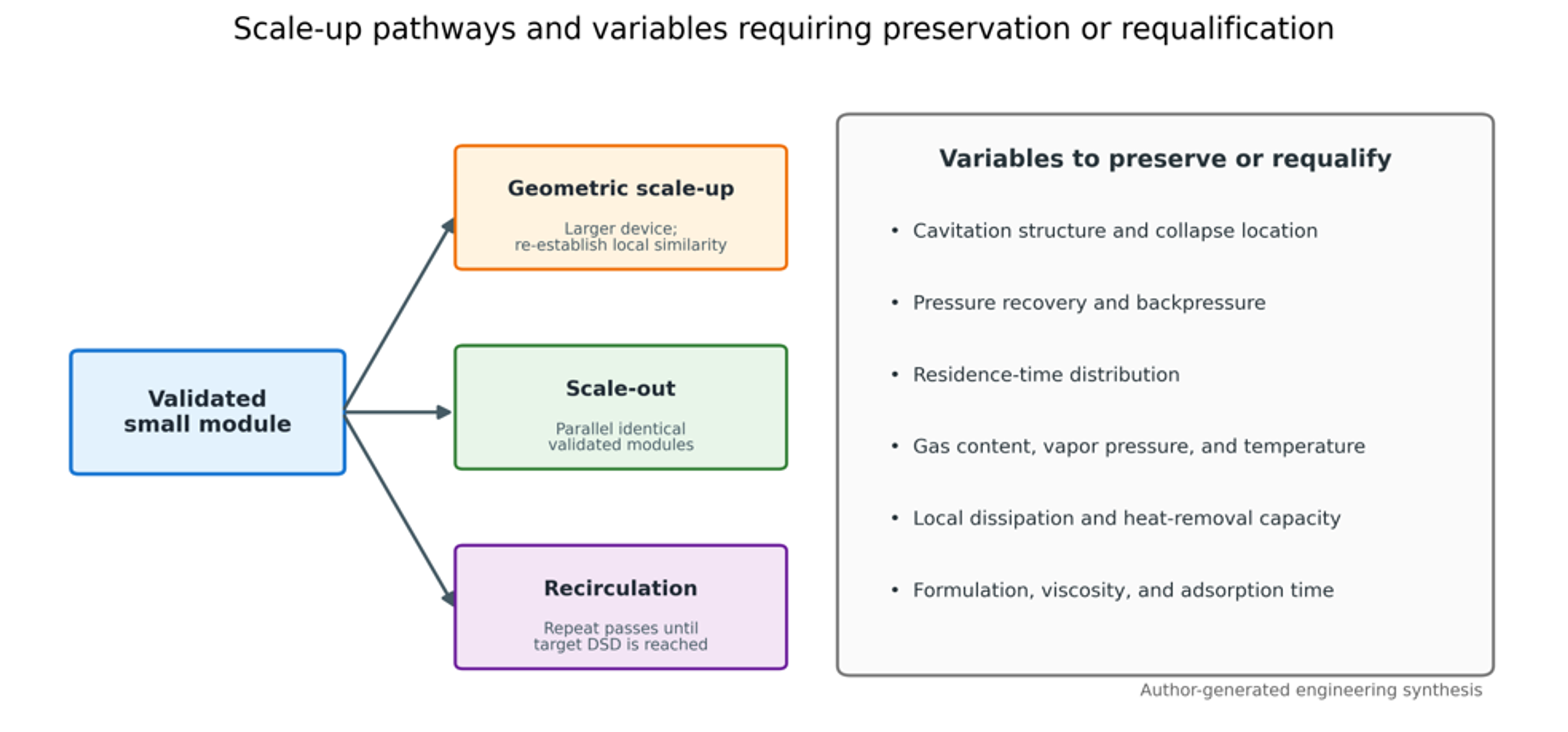
Figure 34. Scale up pathways and variables that must be preserved or requalified [9].
Geometric similarity alone is insufficient because cavitation depends on local pressure recovery, vapor volume, turbulent dissipation distribution, bubble residence, and the probability that droplets enter the active region. A device can preserve cavitation number and still change droplet size because the spatial distribution of stress has changed.
The Euler number used for hydraulic comparison is:
A useful, simulated cavitation extent metric is:
where is vapor volume in a defined region and is device volume. Neither metric alone predicts emulsification. The dispersed phase trajectory and local collapse dissipation must also be considered [29].
Scale out often preserves local hydrodynamics most reliably because each module operates near its validated point. It adds manifolds, valves, sensors, cleaning branches, and the possibility of unequal flow distribution. A well designed manifold should maintain similar pressure drop across each branch and allow isolation of a module without destabilizing the others.
Recirculation is flexible for batch production and formulation development. Its disadvantages are broader residence time distribution, repeated exposure of already fine droplets, greater oxygen pickup, and heat accumulation. A heat exchanger should be sized from measured pump and reactor heat load, not only from theoretical pressure drop power.
Table 12. Comparison of scale up strategies.
| Strategy | Main advantage | Main risk | Best use | Required qualification |
|---|---|---|---|---|
| Geometric scale up | Fewer large units and simple piping | Active cavitation structure may not scale geometrically | High throughput mature process with validated model | Pressure field, vapor extent, DSD, heat removal, erosion |
| Scale out | Preserves validated local device behavior | Manifold imbalance and more components | Modular production and regulated products | Branch flow balance, cleaning, control logic, failure isolation |
| Recirculation | Flexible endpoint and small reactor | Diminishing returns and broad exposure history | Batch products and pilot development | Pass distribution, temperature, oxidation, tank mixing |
| Multi inlet design | Higher capacity in one chamber | More complex inlet manifold and swirl interaction | Moderate capacity increase at low pressure drop | Symmetry, inlet balance, cavitation core stability |
| Hybrid train | Each stage performs a specific function | More equipment and control interactions | Premix plus cavitation plus polishing | Stage by stage DSD, energy, and compatibility |
8.2 Instrumentation and process control
At minimum, an industrial cavitation line should measure flow, upstream pressure, downstream pressure, inlet and outlet temperature, motor or pump power, and product pressure limits. High speed pressure transducers, acoustic emission sensors, turbidity, optical backscatter, and at line droplet size sensors can provide regime information. A 2025 study demonstrated at line estimation of dense emulsion droplet size distributions with a simple voltage based sensor, indicating a path toward continuous quality monitoring [70].
A control system may use flow and backpressure as manipulated variables for a static device or add rotor speed for a dynamic device. Product temperature should act as a constraint. A useful cascade is: maintain flow with pump speed, maintain downstream recovery pressure with a backpressure valve, limit outlet temperature with heat exchange, and adjust pass number or recirculation time from an at line product indicator.
Process analytical technology should be calibrated against an accepted reference method. Turbidity or voltage can correlate with only within a defined composition, optical property, temperature, and phase fraction. Formula changes require recalibration.
8.3 Materials, erosion, sanitation, and maintenance
Cavitation erosion is concentrated where collapse occurs near surfaces. Vortex designs can shift the active core away from the wall, while orifices and sharp edges may require replaceable inserts. Material selection should consider hardness, corrosion resistance, fatigue, surface finish, thermal expansion, and cleaning chemistry. For food and pharmaceutical service, weld quality, drainability, clean in place coverage, and elastomer qualification are mandatory.
Erosion monitoring can use weight loss of replaceable coupons, profilometry, pressure drop drift, vibration, metal particle analysis, or scheduled borescope inspection. A rising pressure drop at constant flow may indicate fouling or damaged geometry. A falling pressure drop may indicate edge rounding or enlargement, both of which can change the cavitation regime before a visible failure occurs.
8.4 Design workflow
A disciplined development program separates formulation limits from equipment limits. The recommended sequence is:
-
Define product quality by full DSD, rheology, stability, chemistry, and throughput.
-
Establish a premix that is pumpable and does not separate before the reactor.
-
Measure density, viscosity, vapor pressure, and dynamic interfacial tension at process temperature.
-
Screen cavitation regime, pressure, backpressure, and pass number at laboratory or pilot scale.
-
Quantify energy, temperature rise, gas pickup, and chemical degradation.
-
Fit a correlation or reduced model within the validated operating window.
-
Select geometric scale up, scale out, or recirculation and verify the active cavitation structure.
-
Conduct extended reliability, cleaning, and storage trials with production equivalent materials.
Table 13. Minimum pilot test matrix for a new formulation.
| Factor | Suggested levels or method | Primary response | Secondary response |
|---|---|---|---|
| Pressure drop | Low, intermediate, high around inception and optimum | , , Span | Temperature rise and hydraulic energy |
| Backpressure | At least three recovery pressure levels | Cavitation regime and DSD | Gas release and erosion indicator |
| Pass number | 1, 2, 3, 5, and endpoint specific higher value | Diminishing return curve | Oxidation and active retention |
| Dispersed phase fraction | Minimum, nominal, maximum formulation | DSD and rheology | Pumpability and phase inversion |
| Emulsifier level | Below, near, and above anticipated coverage | Recoalescence and storage stability | Cost, sensory or toxicity constraints |
| Temperature | Low, nominal, maximum allowed | Viscosity and diameter | Chemical degradation and vapor pressure |
| Gas condition | As received, degassed, controlled gas addition if relevant | Reproducibility and foam | Dissolved oxygen and collapse intensity |
| Residence or flow | At least three throughputs | Capacity and DSD | Pressure loss and heat transfer |