
Technical publication
Back to publications
Reactors & equipment
Hydrodynamic Cavitation in Emulsification and Homogenization
okozyuk.com
Published
Read complete publication for whole-document Find and printing. Browser Find and native printing on this reader include only loaded content.
5 Equipment and Process Configurations
5.1 Static constriction devices
Static devices create a pressure decrease without moving internal parts. Orifices provide abrupt contraction and expansion, strong jets, and compact construction. Venturis provide smoother acceleration and pressure recovery. Cone, baffle, and nozzle devices offer additional control of the low pressure region and collapse location. Studies show that throat geometry, recovery profile, and cavitation number definition must be assessed together because nominal pressure drop alone does not identify the active breakup field [5–8,19,31,33–35].
Table 6. Hydrodynamic cavitation device families for emulsification and homogenization.
| Device family | Cavitation generation mechanism | Principal control variables | Strengths | Limitations |
|---|---|---|---|---|
| Orifice plate | Jet and vena contracta pressure decrease | Hole number, diameter, area ratio, edge, pressure drop | Simple, low cost, replaceable insert | Clogging, erosion, abrupt recovery, broad residence time distribution |
| Circular Venturi | Smooth acceleration through a throat | Throat diameter, convergent/divergent angles, length, backpressure | Good throughput, controlled recovery | Larger footprint, geometry sensitive cavitation location |
| Slit Venturi | Planar acceleration and shear | Slit width, height, aspect ratio, pressure | High pass rate and strong planar deformation | Narrow slit can be sensitive to solids and fouling |
| Cone or bluff body | Separated cavity behind body | Cone angle, blockage, channel diameter, backpressure | Visual access and controllable attached cavity | Supercavitation can reduce discrete collapse events |
| Vortex device | Low pressure swirling core | Inlet number, chamber aspect ratio, outlet, pressure drop | Open passages, cavitation away from walls, modular | Performance sensitive to swirl stability and droplet trajectory |
| Liquid whistle or jet device | Jet oscillation, impact, and cavitation | Jet velocity, resonator geometry, backpressure | Compact and effective for recirculation | Acoustic and erosion behavior can be geometry dependent |
| Rotor stator cavitator | Periodic cavities and high relative velocity | Rotor speed, gap, holes or grooves, flow, backpressure | Independent speed control and strong combined shear | Moving seals, mechanical complexity, heat, wear |
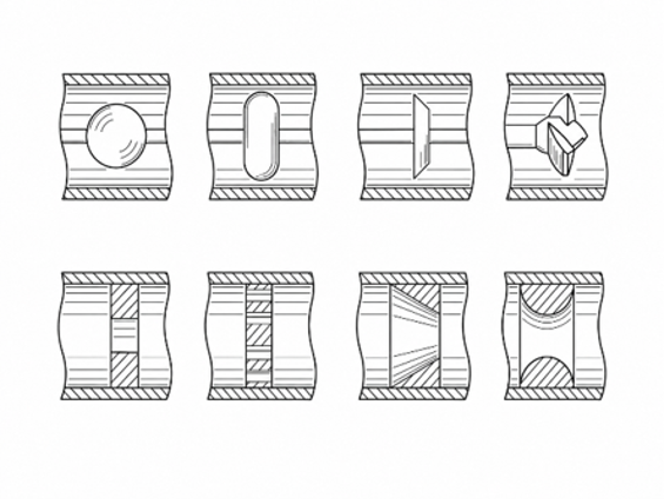
Figure 8. Drawings of controlled flow cavitation devices illustrating inline flow passages and cavitation generating geometries [36].
The Kozyuk patent family illustrates the controlled flow principle: a pressurized stream passes a cavitation generator, cavities form in the low pressure region, and collapse occurs as pressure recovers downstream [36]. The generator shape and recovery chamber are selected to control the bubble field rather than merely maximize pressure loss.
5.2 Vortex based devices
Vortex cavitation devices use tangential inlets to create a rotating flow and low pressure axial core. Cavitation can occur in the bulk fluid away from the wall, which may reduce erosion. The open chamber and millimetre scale clearances are also favorable for streams containing suspended solids or moderate viscosity. Recent studies have varied chamber aspect ratio, inlet number, outlet geometry, scale, and parallel arrangement. An aspect ratio near six was reported as favorable in one design study, while other experiments found that vortex stabilizers and multiple inlets could improve cavitation activity and energy performance, especially at low pressure drop [19,29].
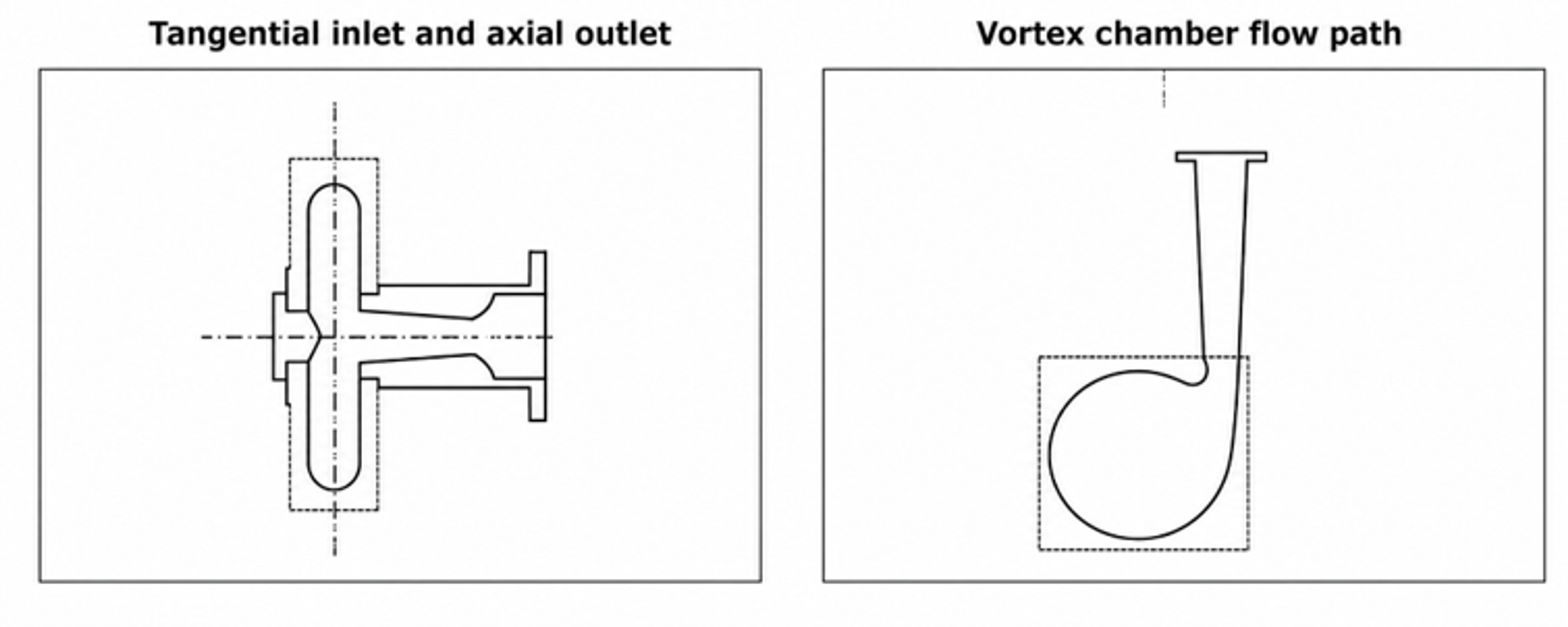
Figure 9. Representative vortex diode cavitation geometry showing a tangential inlet and axial outlet arrangement used to establish a low pressure swirling core [37].
Vortex geometry must be evaluated by both vapor generation and droplet trajectory. A large cavitation region does not guarantee effective emulsification if the dispersed phase bypasses it. This is one reason that CFD models increasingly track water, oil, and vapor phases together and then couple the predicted flow to a PBM [25,29].
5.3 Dynamic rotor stator and rotary cavitation devices
Dynamic devices generate alternating low and high pressure regions by moving cavities, holes, grooves, or blades past a stator. Rotational speed provides a control variable that can be adjusted separately from flow and backpressure. Visualization and CFD of a rotational hydrodynamic cavitation reactor show that hole diameter, hole height, and conical bottom length alter vapor exchange, cavitation area, and vortex intensity [31]. The engineering tradeoff is the addition of seals, bearings, rotor balance, tip speed limits, mechanical heating, and wear.
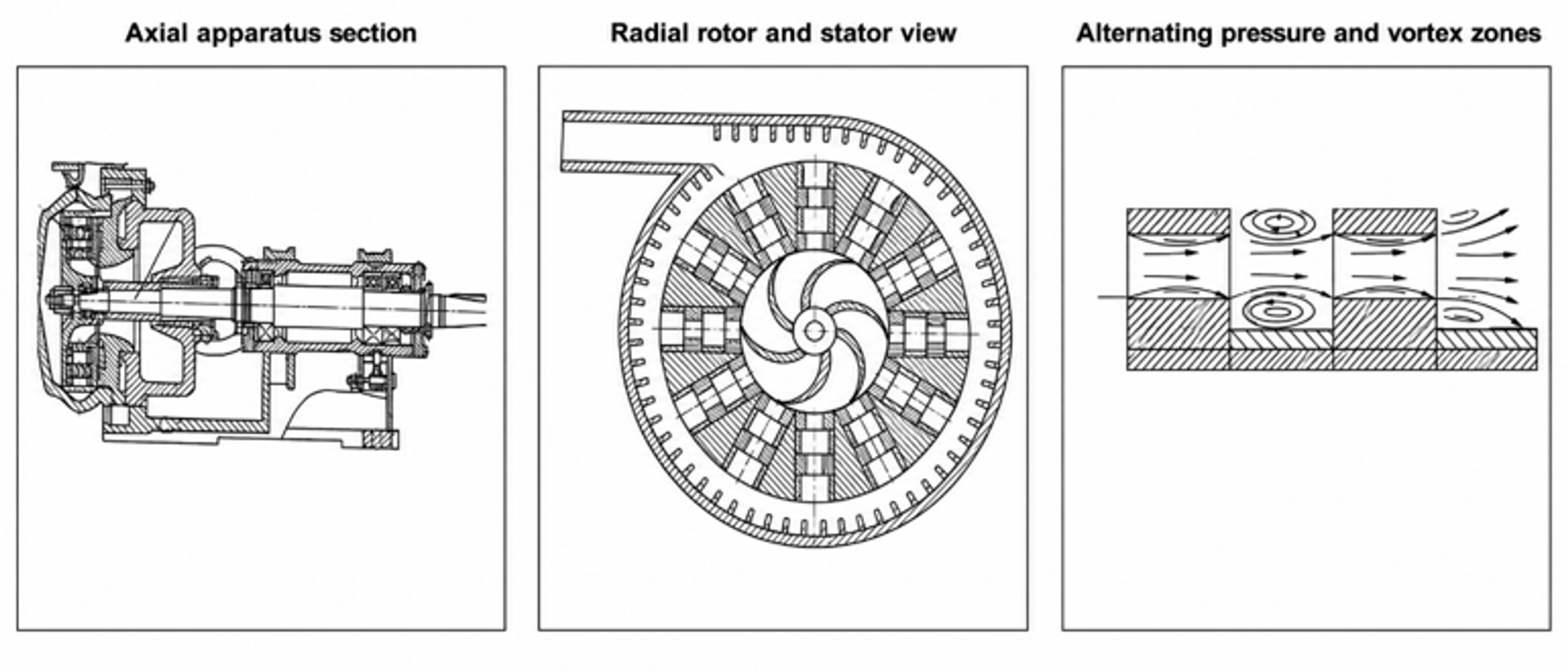
Figure 10. Rotor hydrodynamic cavitation apparatus with perforated or structured rotating elements and stationary housing [38].
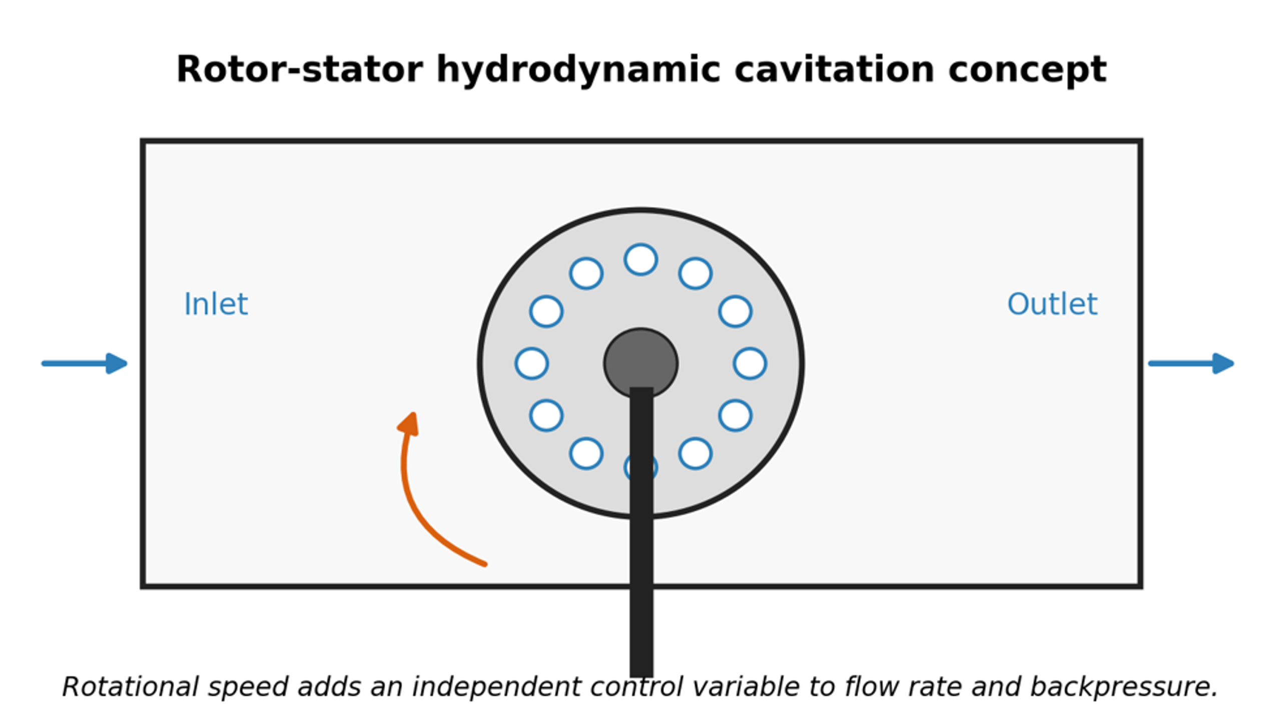
Figure 11. Rotor stator hydrodynamic cavitation concept. Rotation provides an independent variable that can be adjusted separately from flow and backpressure [9].
5.4 Patented food and emulsion process configurations
Patents illustrate how cavitation equipment is integrated into staged industrial processes. The food emulsion patent family represented in Figure 12 uses hydrodynamic cavitation within a controlled process sequence to produce an oil in water food product. Patent examples also cover vortex diodes, inline controlled flow devices, rotor cavitators, and newer hydrodynamic cavitation mixers [36–41]. Patent drawings are useful for identifying process architecture, but performance claims should be confirmed by independent testing with the intended formulation.
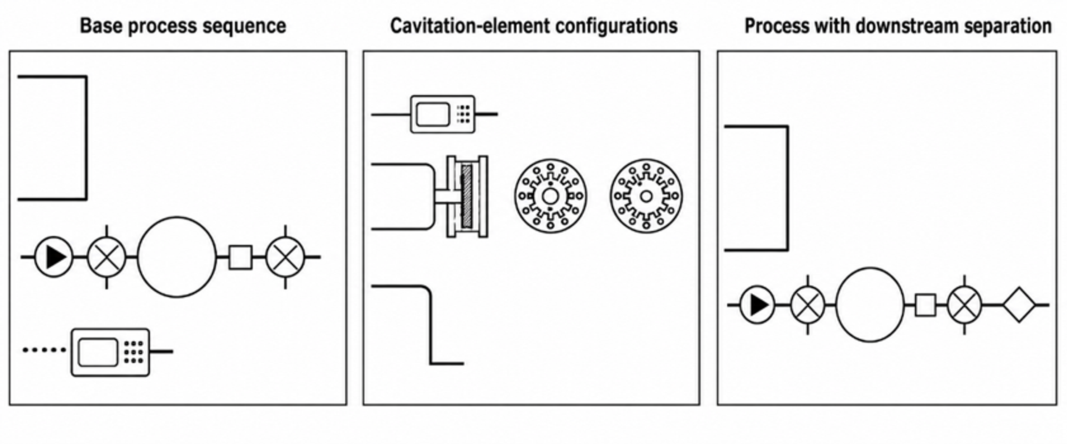
Figure 12. Representative process schemes from a food emulsion patent family that incorporates hydrodynamic cavitation into preparation and phase management steps [39].
5.5 Process integration and production configurations
Commercial implementation usually takes one of three forms: a single pass inline unit, a recirculation loop, or several identical modules operated in parallel. Selection depends on residence time tolerance, validated local cavitation conditions, cleaning strategy, and required turndown. Supplier data can support mechanical design, but product specific droplet size distribution, temperature, chemistry, and wear must be established by pilot testing [42–44].
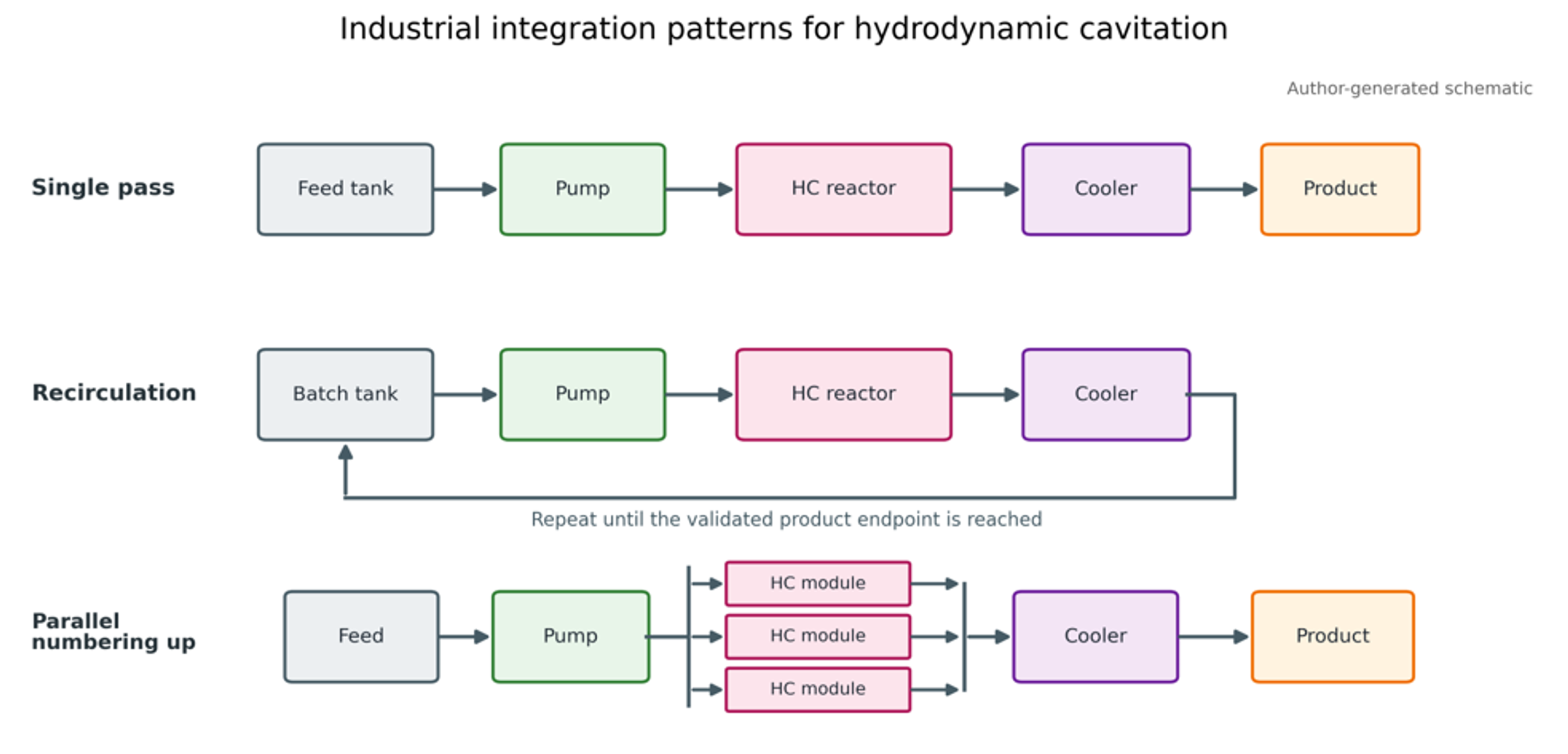
Figure 13. Industrial integration patterns for hydrodynamic cavitation: single pass, recirculation, and parallel scale out [9].
Production installation normally includes a feed or recirculation tank, pump, cavitation reactor, upstream and downstream pressure measurement, flow measurement, backpressure valve, heat exchanger, sampling point, and route for single pass discharge or recirculation. For sanitary products, drainability, elastomer compatibility, surface finish, clean in place velocity, dead leg control, and validated cleaning are as important as cavitation intensity.