
Technical publication
Back to publications
Industrial applications
Hydrodynamic Cavitation for Wastewater Processing
okozyuk.com
Published
Read complete publication for whole-document Find and printing. Browser Find and native printing on this reader include only loaded content.
3 Hydrodynamic Cavitation for Wastewater Treatment
3.1 Position in the Treatment Train
Hydrodynamic cavitation is best applied as a targeted unit operation rather than as a universal replacement for primary treatment, biological treatment, or separation processes. In municipal treatment, HC may be positioned before biological treatment to improve biodegradability, after biological treatment to reduce micropollutants and residual pathogens, or in a sludge side stream. In industrial treatment, it may pretreat concentrated or toxic streams, intensify oxidant contact, or provide polishing before reuse. Placement should be determined by the dominant process limitation, including mass transfer, biodegradability, particle accessibility, toxicity, or microbial risk [1-8].
Published studies indicate that performance measured for a single compound in clean water can overestimate treatment in real effluent. Carbonate, bicarbonate, chloride, natural organic matter, suspended solids, oils, surfactants, and coexisting contaminants can consume radicals and modify bubble dynamics. Conversely, suspended solids and gas bubbles can supply nuclei and increase the number of cavitation events. These competing effects make matrix specific testing necessary [1,2,4,8].
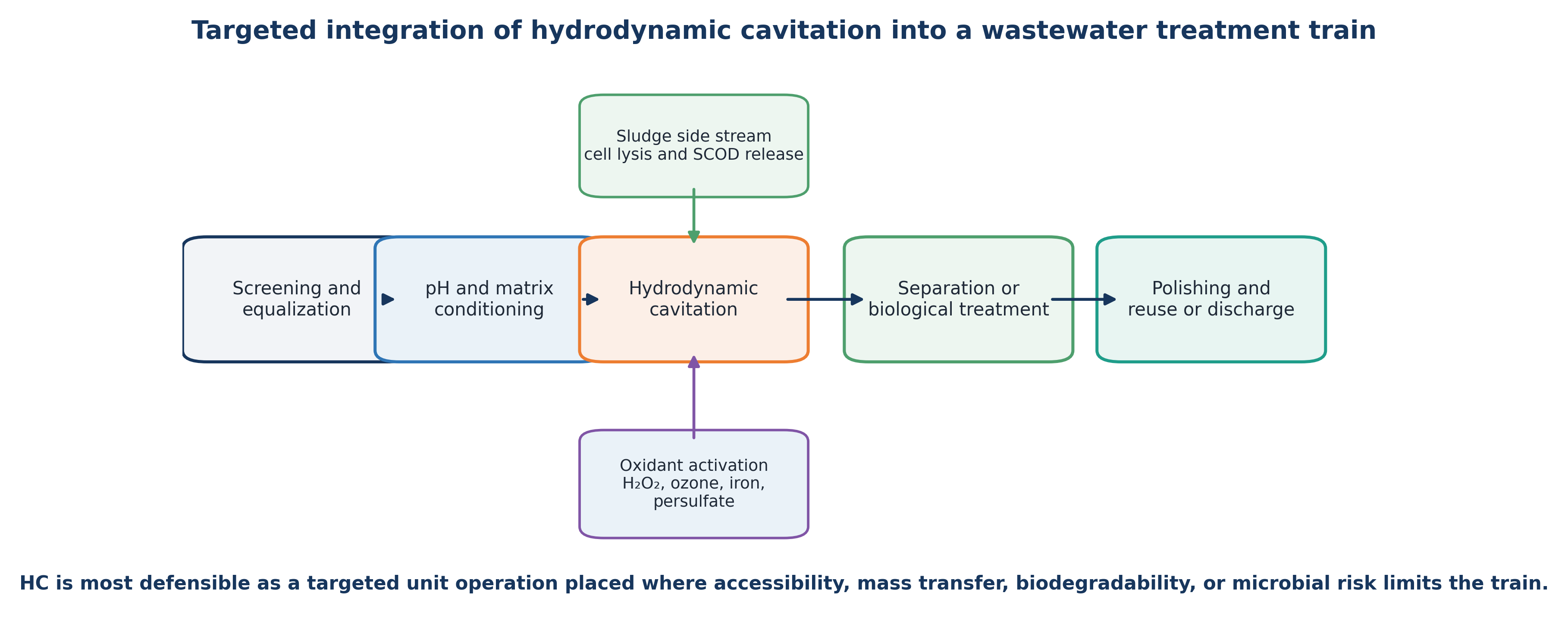
Figure 3.1. Targeted positions for hydrodynamic cavitation in municipal and industrial wastewater treatment trains [11].
3.2 Model Compounds and Optimization of Hydraulic Severity
The p-nitrophenol study by Capocelli et al. illustrates a nonmonotonic pressure response. In a 1.5 L recycle apparatus with a transparent Venturi, inlet pressure was varied from 0.2 to 0.7 MPa. Removal rate and energy efficiency were optimized near 0.4 to 0.45 MPa, corresponding to a reported cavitation number close to 0.25. At 0.45 MPa, the observed first order rate constant was approximately 1.13 × 10⁻² min⁻¹ and EEO was 66.7 kWh m⁻³ per order [16]. Further pressure increase raised hydraulic demand and altered cavity behavior without a proportional chemical benefit.
This result illustrates a broader design principle. Weak cavitation produces too few intense collapse events, whereas developed cavitation can provide a large population of productive events. At excessive severity, vapor shielding, coalescence, long attached cavities, choked flow, and nonproductive energy dissipation can reduce the fraction of input energy converted to useful collapse. The operating optimum should therefore be determined experimentally using a chemical or biological response together with an energy normalized metric.
3.3 Real Industrial Wastewater, Landfill Leachate, and Nutrient Removal
Studies in real wastewater demonstrate both the potential and the limitations of standalone HC. Korniluk and Ozonek treated mature landfill leachate in a recycle loop with a four slot orifice reactor operating at approximately 7 bar, 46.5 L min⁻¹, and a total liquid volume of about 40 L. After 30 minutes, COD decreased by 6.7% and TOC by 5.1%, while temperature increased by approximately 11 °C [19]. These modest removals are consistent with the high concentration and refractory character of mature leachate. Under such conditions, HC is more plausibly used as pretreatment or for oxidant activation than as the sole mineralization process.
Badve and coworkers studied actual wood finishing wastewater with an initial COD of approximately 38,000 mg L⁻¹ and pH 6.18. The rotating cavitator used a rotor with 204 surface indentations. COD reduction depended on rotor speed, residence time, and peroxide dose. The study reported an optimum near 2200 rpm and an optimum H₂O₂ loading near 5 g L⁻¹. Under the tested conditions, HC alone produced substantial COD reduction, while the optimized HC peroxide process increased cavitational yield by approximately 46% [20]. Higher peroxide loading reduced the benefit, which is consistent with radical scavenging.
In an industrial advanced Fenton study, a 25 L recirculating hydrocavitator was coupled with zero valent iron and hydrogen peroxide. The feed was a complex substituted phenolic effluent with reported pH 1.7, COD of about 42,000 mg L⁻¹, and TOC of about 14,000 mg L⁻¹. Under otherwise comparable conditions, TOC removal increased from about 50% at 500 psi to 52% at 1000 psi and 60% at 1500 psi. A 15 minute active treatment followed by storage also produced continued mineralization, indicating that cavitation initiated chemistry that persisted after hydraulic exposure [70].
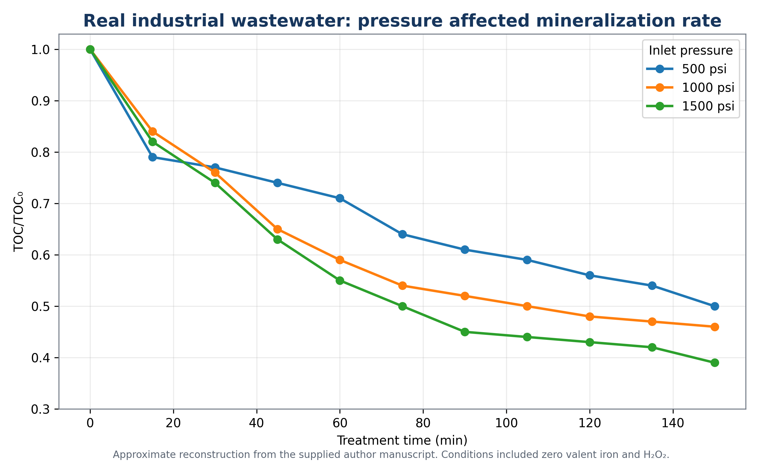
Figure 3.2. Effect of hydrocavitator inlet pressure on total organic carbon mineralization in industrial wastewater treated with heterogeneous advanced Fenton chemistry [70].
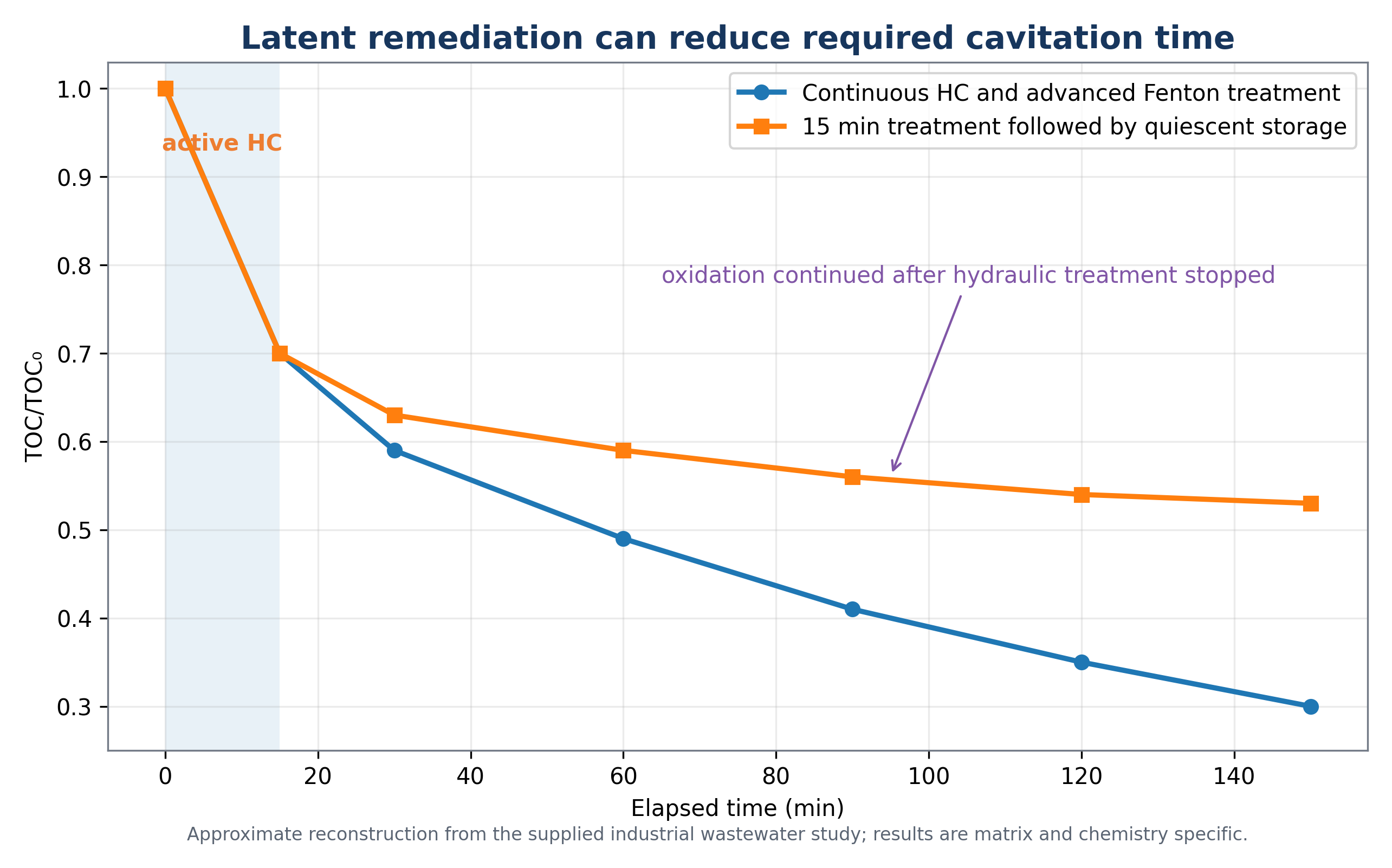
Figure 3.3. Continuous treatment and latent remediation after a short active cavitation period [70].
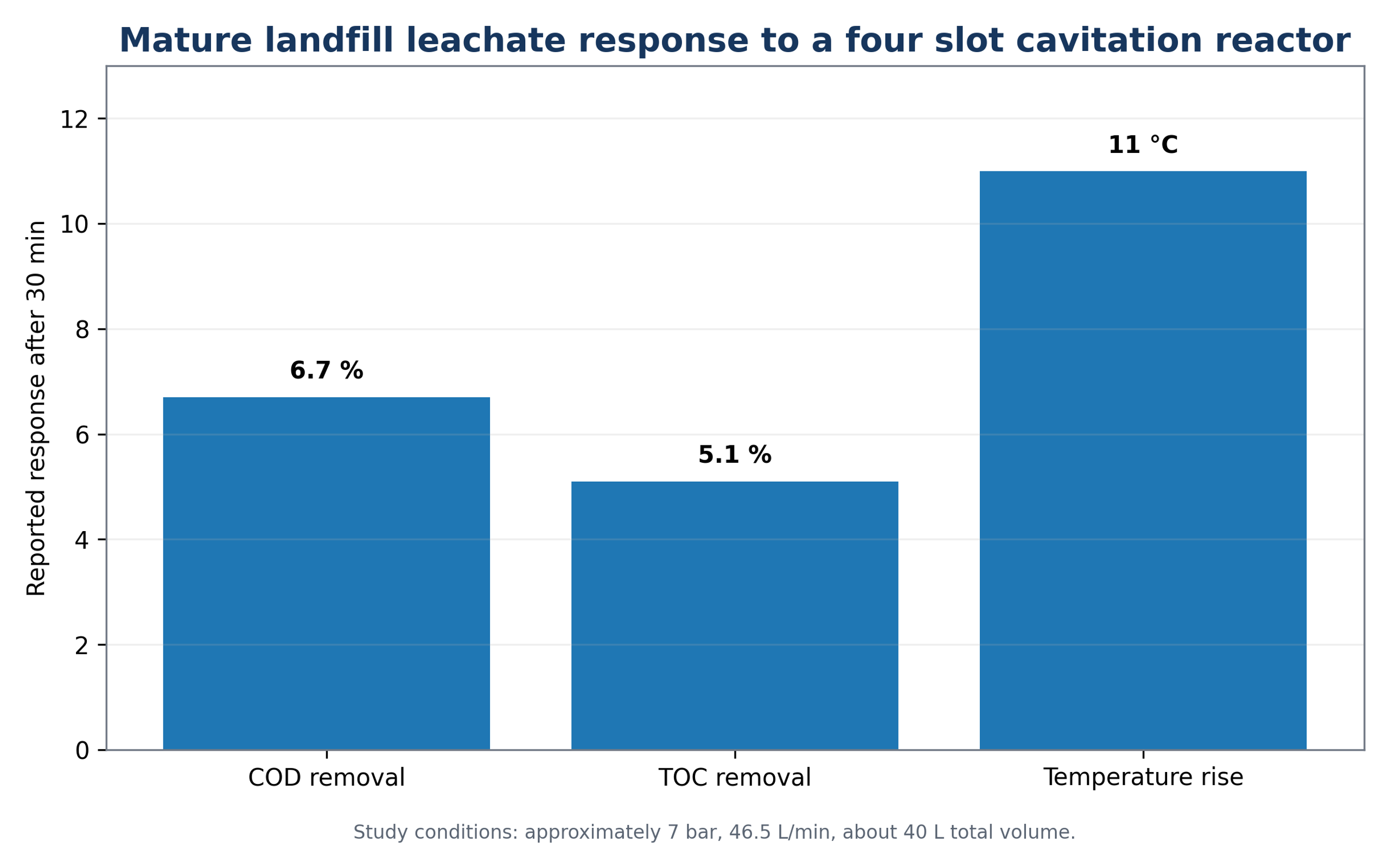
Figure 3.4. Response of mature landfill leachate during 30 minutes of recirculating hydrodynamic cavitation [19].
A separate phosphate removal study applied 20% calcium hydroxide slurry before HC to intensify precipitation and dispersion. Approximately 70% phosphate reduction was reported, with a jet nozzle producing the best result among the tested devices [26]. This application is based on physicochemical precipitation rather than radical oxidation and demonstrates that HC can improve dissolution, dispersion, nucleation, and contact efficiency even when oxidation is not the primary removal mechanism.
For micropollutant polishing, one liter of water containing six model pharmaceuticals was repeatedly passed through a narrow Venturi at initial pressures of 4, 5, and 6 bar in the presence of hydrogen peroxide. The 6 bar condition produced the highest reported removals, but response varied substantially among compounds, from approximately 45% for clofibric acid to 86% for naproxen [44]. A more recent study applied ozone assisted HC to antibiotic contaminated aquaculture seawater, illustrating the transition toward integrated gas liquid transfer, oxidant activation, and treatment train design rather than cavitation alone [49].
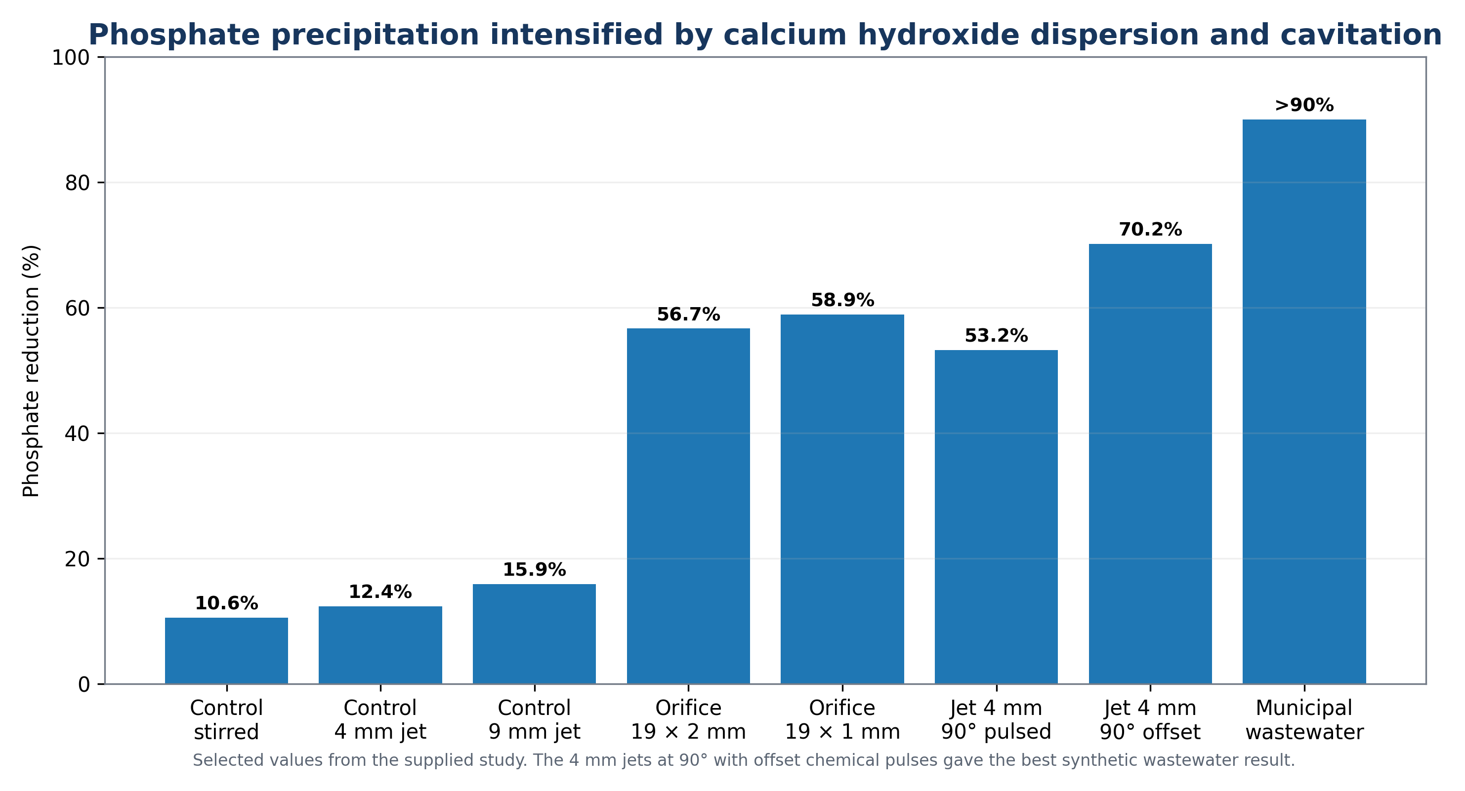
Figure 3.5. Phosphate reduction reported for mixing, orifice plate, and jet nozzle configurations using calcium hydroxide slurry [26].
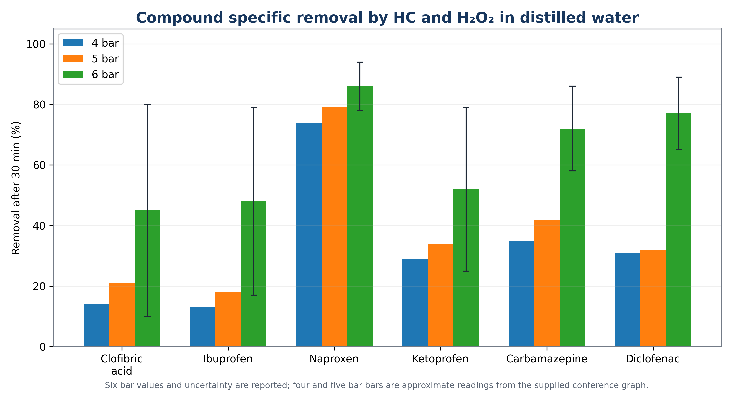
Figure 3.6. Removal of six pharmaceuticals after hydrodynamic cavitation with hydrogen peroxide at 6 bar [44].
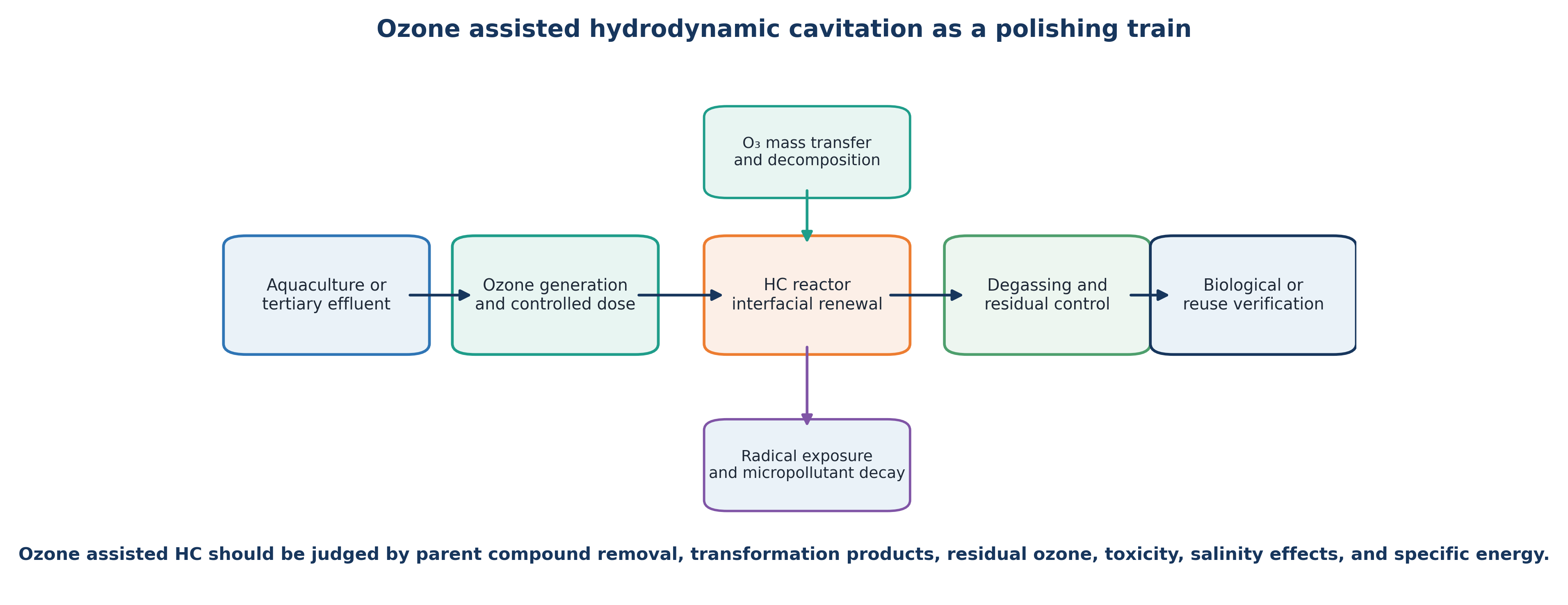
Figure 3.7. Conceptual ozone assisted hydrodynamic cavitation treatment train for antibiotic contaminated water [7,8,49].
Table 3.1. Representative HC wastewater treatment studies from the reviewed and recent literature.
| Matrix or target | Reactor and treatment | Representative result | Engineering interpretation |
|---|---|---|---|
| p Nitrophenol | Recycle Venturi, 0.2-0.7 MPa | Optimum near 0.4-0.45 MPa; EEO 66.7 kWh m⁻³ per order | Maximum pressure was not the optimum [16] |
| Landfill leachate | Four slot orifice, 7 bar, 30 min | COD 6.7%; TOC 5.1% | Standalone HC gave limited mineralization in a refractory matrix [19] |
| Wood finishing wastewater | Rotor stator with indentations, HC and H₂O₂ | COD reduction and yield improved at an optimum dose; yield +46% | Rotor speed, residence time, and oxidant dose must be jointly optimized [20] |
| 2,4-D herbicide | HC plus zero valent iron and H₂O₂ | Residual TOC about 30% after 20 min in the reported continuous treatment | Advanced Fenton chemistry supplied radicals beyond those generated by water alone [22] |
| 2-Chlorophenol | Venturi enhanced cavitation oxidation process | Higher H₂O₂ dose increased degradation, but efficiency favored mild cavitation and controlled injection | Fast treatment and minimum energy can require different operating points [21] |
| Phosphate containing wastewater | Ca(OH)₂ slurry plus orifice or jet HC | About 70% phosphate reduction | HC intensified precipitation and solids contact [26] |
| Wastewater pharmaceuticals | HC with H₂O₂, ozone, Fenton, persulfate, plasma, or catalysts | Performance depends strongly on compound and water matrix | Hybrid selection should be driven by reaction domain and scavenging [45-47] |
The landfill leachate experiment also demonstrates the importance of recording temperature as a response variable. During 30 minutes of recirculation, liquid temperature increased by approximately 11 °C while COD and TOC decreased by only 6.7% and 5.1%, respectively. Most absorbed hydraulic energy was therefore expressed as bulk heating rather than deep mineralization. Evaluation based only on removal percentage would not capture this energy partitioning [19].
In concentrated wastewater with high radical scavenging capacity, a modest change in COD or TOC does not necessarily indicate that pretreatment is ineffective. Molecular weight distribution, biodegradability, toxicity, color, volatile compounds, and downstream biological oxygen demand may change before extensive mineralization occurs. These secondary endpoints should be measured when HC is intended as pretreatment rather than as a final oxidation process.
3.4 Design Implications for Real Effluents
The treatment objective should be defined before operating conditions are selected. Parent compound removal is sufficient only when transformation products are known and acceptable. COD and TOC are required when bulk oxidation or mineralization is the objective. The biochemical oxygen demand to COD ratio, respirometry, or biochemical methane potential can quantify changes in biodegradability. Toxicity assays are required when reactive intermediates may form. Color removal and ultraviolet absorbance are useful supplementary indicators but can be misleading when chromophores are destroyed without corresponding carbon removal.
A staged treatment sequence is often preferable. Coarse solids or free oil can be removed first to avoid unnecessary hydraulic duty. HC can then be applied within a concentration and pH range that provides access to the target. Biological treatment can remove biodegradable products, and final polishing can address residual micropollutants or microbial risk. This approach confines the high intensity step to locations where it contributes measurable value and avoids attempting to mineralize the entire organic load by cavitation alone [23-25].
3.5 Equipment Selection and Hydraulic Integration
Reactor selection must account for wastewater characteristics and system integration. Low solids pharmaceutical polishing can use narrow Venturi or orifice passages with controlled oxidant injection. Fibrous, oily, or particulate streams require larger flow paths, maceration, flushing provisions, or dynamic devices with solids tolerant clearances. Sludge service requires positive displacement or progressive cavity pumping, controlled temperature rise, and grit protection. Highly corrosive industrial effluent may require lined piping, compatible elastomers, and replaceable cavitation elements.
The controlled cavitation equipment described by Nicholas and Vella used pressure equalization chambers and opposed truncated nozzles to form a collision region within a central chamber. A transparent demonstration chamber allowed visualization of the cavitation cloud. The arrangement demonstrates how equalized feed pressure and opposed flow can localize collapse without relying on a single downstream wall. Because the reported sludge benefits were obtained in a developer affiliated pilot study, the equipment photographs provide useful design information, whereas performance claims require independent verification at the intended duty [59].
A minimum instrumentation package should measure upstream and downstream pressure, flow rate, liquid temperature, motor or pump power, and treatment time. Hybrid processes should additionally measure pH, oxidant dose, residual oxidant, dissolved oxygen or ozone transfer, and off gas. Sampling must distinguish instantaneous pass performance from the cumulative response of a recycle tank. Loop volume, dead volume, bypass flow, cooling duty, and nominal turnover count should be reported.
Table 3.2. Wastewater matrix and equipment selection considerations.
| Matrix or objective | Preferred reactor features | Main risks | Essential controls |
|---|---|---|---|
| Low solids micropollutant polishing | Venturi, orifice, vortex, or jet with controlled oxidant contact | Radical scavenging, overdosage, low single pass conversion | Pressure, flow, pH, oxidant residual, EEO, transformation products |
| Concentrated industrial wastewater | Recycle loop, staged oxidation, heat rejection, sampling between stages | Bulk heating, incomplete mineralization, toxicity of intermediates | COD, TOC, biodegradability, toxicity, temperature, specific energy |
| Waste activated sludge | Large passages or rotational device, macerator, positive displacement pumping | Grit wear, plugging, excessive solubilization, foaming changes | SCOD, particle size, viscosity, BMP, torque, temperature |
| Oily or emulsified wastewater | Jet, vortex, or rotor with downstream flotation or separation | Stable emulsification when separation is intended | Droplet size, oil removal, gas transfer, flotation performance |
| Precipitation and nutrient removal | Rapid dispersion and nucleation followed by clarification or filtration | Fine solids carryover and scaling inside the reactor | pH, reagent stoichiometry, particle size, settling, pressure loss |
| Disinfection and reuse | Repeated pressure cycles with validated biological endpoint | Sublethal injury, regrowth, shielding by solids | Culture and infectivity assays, turbidity, temperature, LRV, residual control |