Technical publication
Back to publications
Hydrodynamic Cavitation for Wastewater Processing
okozyuk.com
Published
Hydrodynamic Cavitation for Wastewater Processing
Abstract
Hydrodynamic cavitation (HC) is evaluated as a process intensification method for wastewater treatment, sludge pretreatment, ballast water treatment, disinfection, and oxidation of refractory organic contaminants. The article examines aqueous reaction zones, reactor configurations, hydraulic operating windows, hybrid oxidation, sludge disintegration, biological inactivation, scale up, energy accounting, materials, and control requirements. The reviewed evidence indicates that treatment performance is governed by the controlled sequence of cavity inception, growth, transport, and collapse and by interaction with the water matrix rather than by cavitation number or pressure alone. Static and rotational reactors can intensify oxidation, mass transfer, particle disintegration, microbial inactivation, precipitation, and anaerobic digestion, but response depends strongly on contaminant properties, dissolved gas, solids, radical scavenging, backpressure, temperature, residence time, and auxiliary chemistry. Case studies demonstrate nonmonotonic pressure response, limited standalone mineralization in strongly scavenging matrices, improved methane yield after optimized sludge disintegration, and enhanced micropollutant removal when HC is coupled with hydrogen peroxide, ozone, Fenton chemistry, plasma, or other advanced oxidation processes. Scale up should preserve process function and be verified through continuous pilot testing, energy normalization, byproduct and toxicity assessment, and asset condition monitoring. HC is therefore most effectively implemented as a targeted unit operation within an integrated treatment train rather than as a universal replacement for conventional treatment.
1 Introduction
This article applies consistent hydraulic definitions, energy boundaries, residence time expressions, uncertainty requirements, and scale translation principles to hydrodynamic cavitation for water processing. The discussion focuses on mechanisms, process models, design variables, and acceptance criteria specific to wastewater, sludge, ballast water, and disinfection applications.
Water processing must address contaminant classes that are not reliably removed by conventional clarification and biological treatment. These include refractory organic compounds, pharmaceuticals, pesticides, dyes, solvents, pathogens, algal cells, viruses, and complex solids in waste activated sludge. Hydrodynamic cavitation (HC) is applicable because a single flow through device can generate mechanical, thermal, and chemical effects, commonly near ambient bulk temperature and without requiring an optical path through the liquid [1-8].
Cavitation is the formation, growth, oscillation, and collapse of vapor or gas vapor cavities when local liquid pressure approaches or falls below the vapor pressure. In HC equipment, the pressure trajectory is generated by the flow field. Static devices employ constrictions, Venturi passages, orifices, nozzles, vortex chambers, and bluff bodies, whereas dynamic devices use rotating surfaces, teeth, cavities, holes, or rotor stator gaps. Effective treatment depends not on cavity formation alone, but on the controlled sequence of inception, growth, transport, and collapse and on the spatial distribution of these events throughout the treated volume [3-10].
Hydrodynamic cavitation can perform several distinct process functions. It can serve as a pretreatment that increases the biodegradability of refractory material, a disintegration step that exposes intracellular and extracellular substrates, an oxidation reactor that generates or activates reactive species, a contactor that improves gas or oxidant transfer, or a disinfection step that damages microorganisms through mechanical and chemical mechanisms. These functions should be evaluated separately. A configuration optimized for cell disruption may not be optimal for oxidation of a hydrophilic pharmaceutical, and rapid disappearance of a parent compound does not necessarily imply adequate total organic carbon removal or toxicity reduction [4,5,8].
The literature considered includes foundational reviews, pilot experiments, industrial wastewater studies, sludge processing investigations, jet generated cavitation, ballast water systems, and patents. Reported values are specific to the experimental system. Valid comparison requires consistent treatment of reactor volume, pass number, pressure definition, pump efficiency, water chemistry, temperature, contaminant concentration, and analytical endpoint.
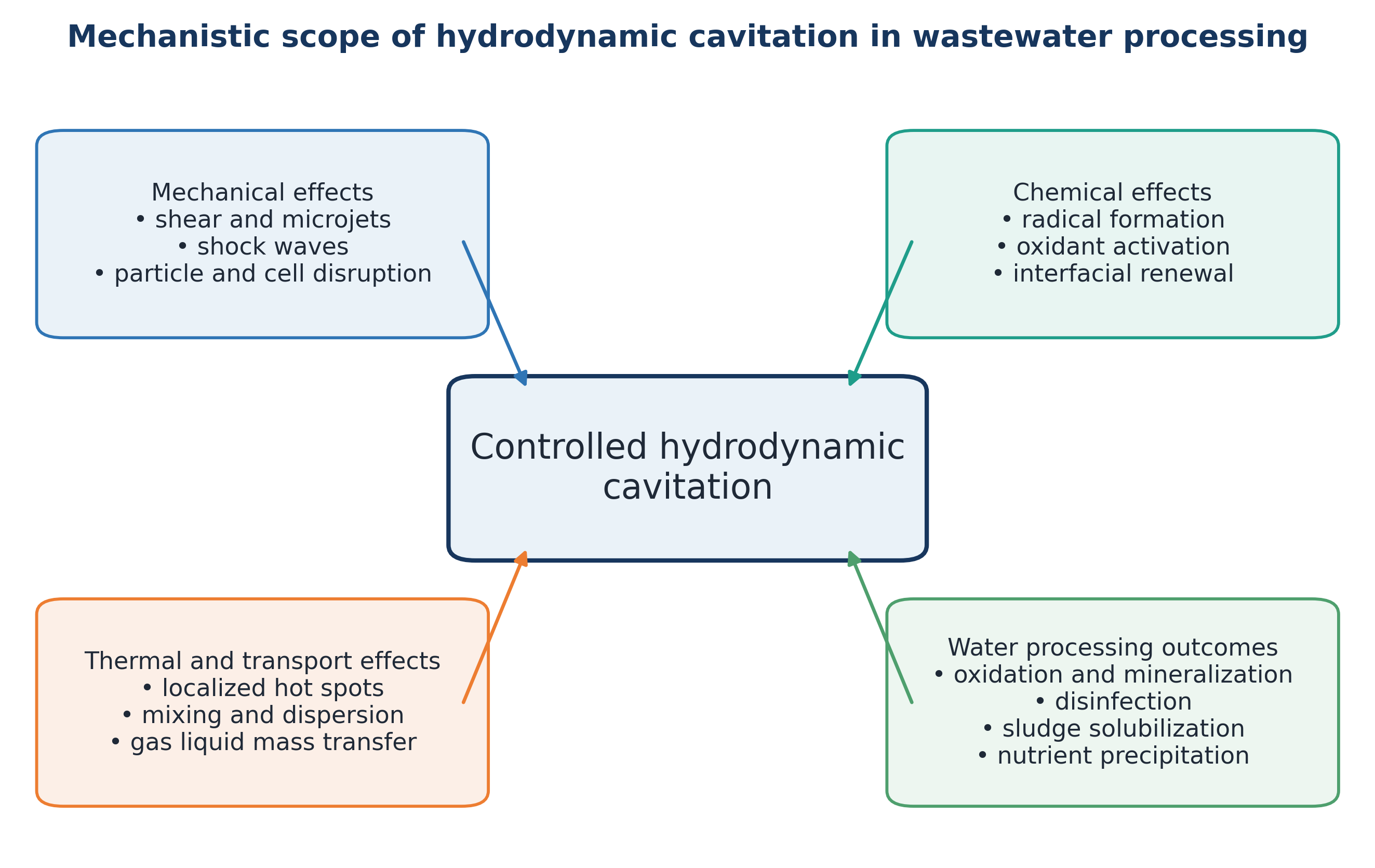
Figure 1.1. Mechanistic scope of hydrodynamic cavitation in wastewater processing [11].
2 Water Phase Reaction Chemistry and Process Response
Standard pressure relations, cavitation number definitions, bubble dynamics, device characteristics, and energy balances provide the hydraulic basis for the following analysis. This section therefore emphasizes aqueous radical chemistry, matrix scavenging, biological response, and treatment train performance.
2.1 Reaction Zones and Radical Chemistry
Three conceptual reaction zones are useful for interpreting contaminant behavior. Volatile compounds can enter an expanding cavity and undergo pyrolytic or radical reactions in the gas vapor core. Hydrophobic and nonvolatile compounds tend to accumulate at the gas liquid interface, where radical concentration, temperature gradients, and shear are high. Hydrophilic nonvolatile compounds remain predominantly in the bulk liquid and depend on radical escape, micromixing, and oxidant activation. The dominant pathway therefore varies with volatility, Henry coefficient, hydrophobicity, concentration, and matrix scavenging [2,4,18,21,45].
Equations (2.3) through (2.6) illustrate why hydrogen peroxide can intensify treatment at an optimum dose but reduce performance when overdosed. Peroxide provides an additional source of hydroxyl radicals while also acting as a radical scavenger. Comparable optima can occur with ozone, persulfate, peroxymonosulfate, Fenton reagents, catalysts, and injected gas. Hybrid chemistry should therefore be optimized using mineralization, toxicity, chemical consumption, and energy as joint criteria rather than by maximizing oxidant dose [21-25,43,45-51].
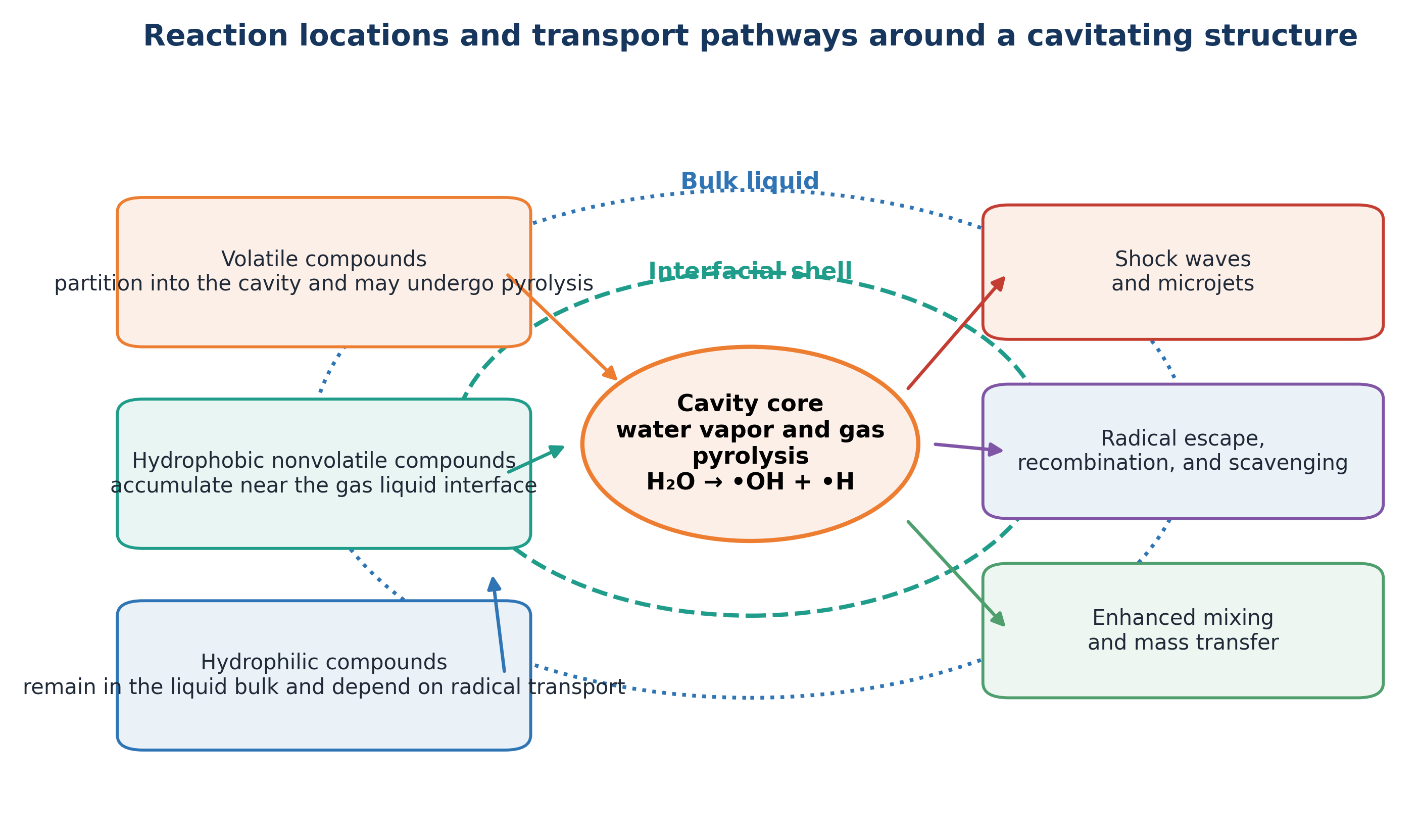
Figure 2.1. Reaction locations and transport pathways around a cavitating structure [11].
2.2 Hydraulic State, Cavity Population, and Reactor Form
For water processing, the controlling hydraulic variable is the population of cavities that experiences a productive pressure history. A sufficiently low local pressure is required for inception, but it does not independently determine chemical or biological performance. Nuclei concentration, dissolved gas, surface tension, viscosity, pressure recovery rate, cavity residence time, cloud interaction, and collapse location can cause devices with similar nominal cavitation numbers to produce different treatment outcomes [3,8,12-15].
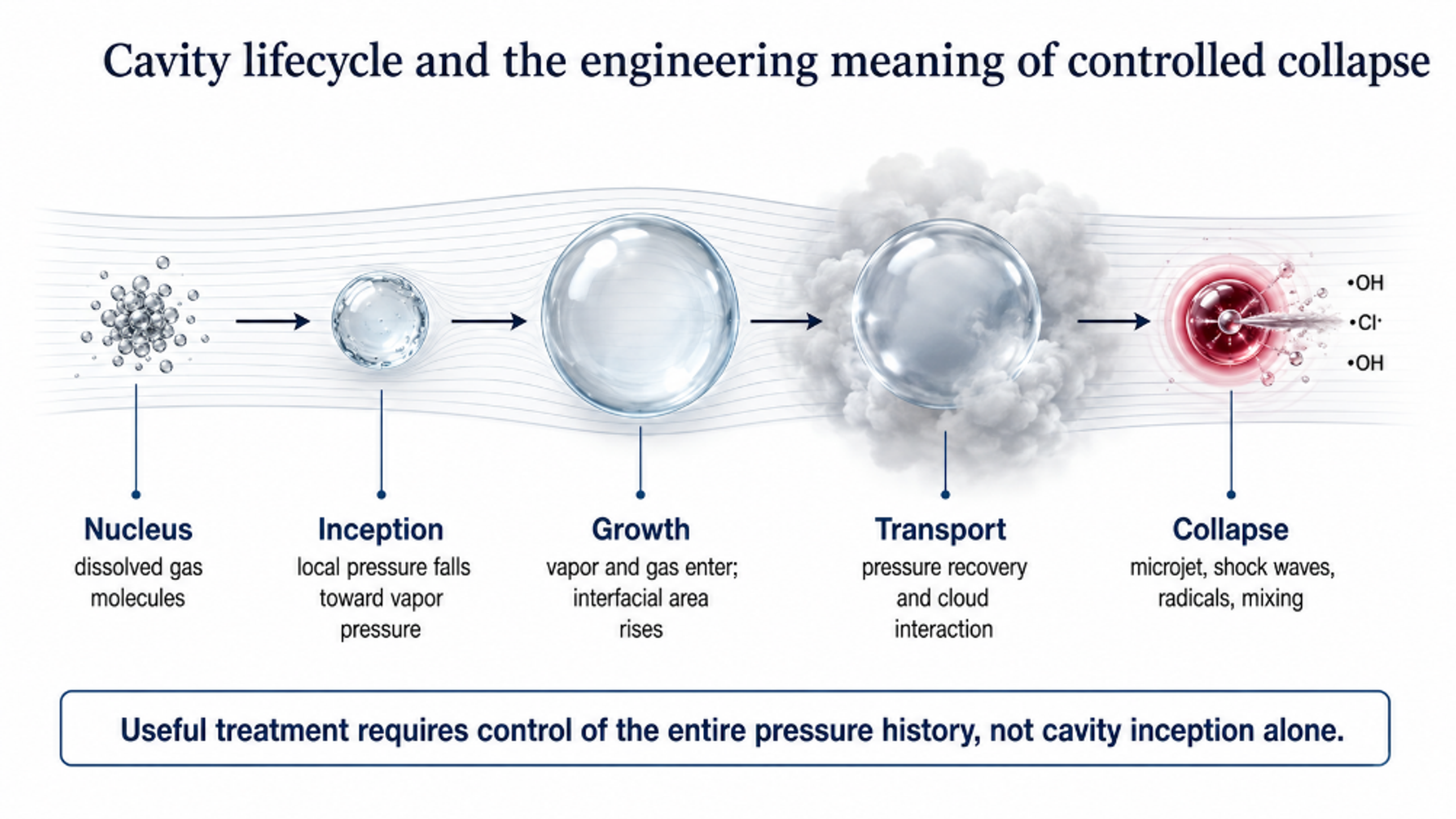
Figure 2.2. Cavity lifecycle and engineering meaning of controlled collapse [11].
Static flow through devices generate cavitation by converting pressure into velocity through an orifice, Venturi passage, nozzle, vortex element, bluff body, or jet. These devices are mechanically simple and can be installed in a recycle loop or a once through line. Their principal engineering limitations include pump duty, blockage by fibrous or coarse solids, nonuniform distribution among parallel openings, and the formation of long vapor structures when downstream backpressure is insufficient.
Dynamic devices generate repeated low pressure regions using a rotor, stator, dimpled disk, toothed surface, or narrow rotating gap. Local velocity and pressure oscillation can therefore be increased without forcing the entire plant flow through a single small constriction. This characteristic can be advantageous for sludge, concentrated industrial streams, and high throughput disinfection. The associated tradeoffs are bearings, seals, rotating clearances, vibration, torque demand, and additional wear surfaces [6-8,31,62].
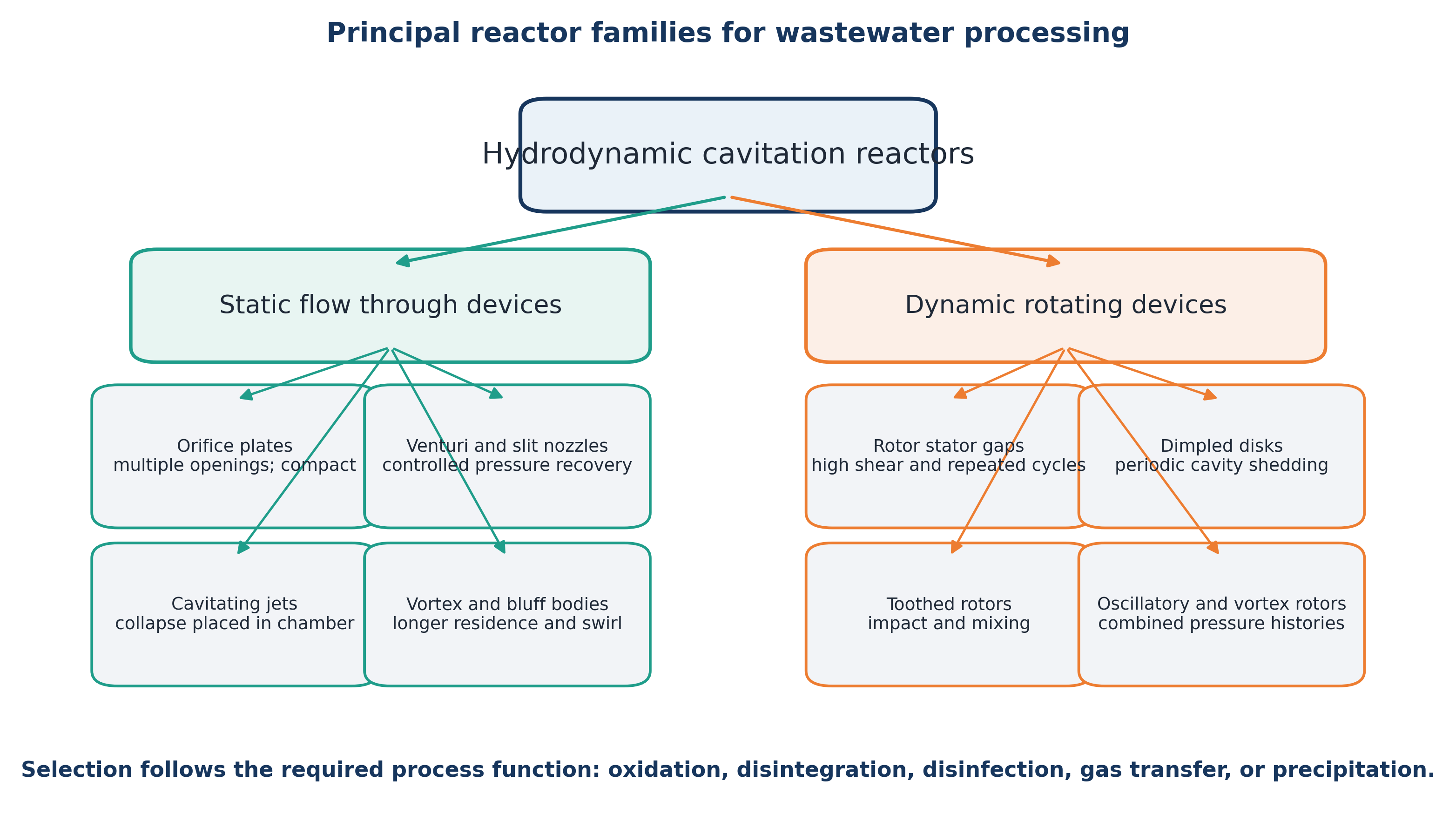
Figure 2.3. Principal reactor families used in wastewater processing [11].
Reactor selection should begin with the required process function. Oxidation requires generation of reactive species and transfer to the relevant reaction domain. Sludge pretreatment requires floc breakup, cell damage, and controlled solubilization. Disinfection may depend on pressure cycling, microjets, shear, radicals, or bulk heating. Gas transfer and precipitation applications depend primarily on interfacial renewal and mixing rather than maximum collapse intensity. Consequently, a reactor that is effective for one function should not be assumed to be optimal for another.
2.3 Cavitating Jets, Nozzles, and Controlled Collapse
Cavitating jets are useful when the collapse region must be localized within a defined chamber. A shear layer forms as liquid exits the nozzle, microscopic nuclei grow in the low pressure jet, and the cavity cloud collapses when it enters a higher pressure region or encounters a stagnation surface. Jet arrays can distribute active regions throughout a vessel, while a downstream target or collision ring can intensify collapse at a selected location [15,56,59].
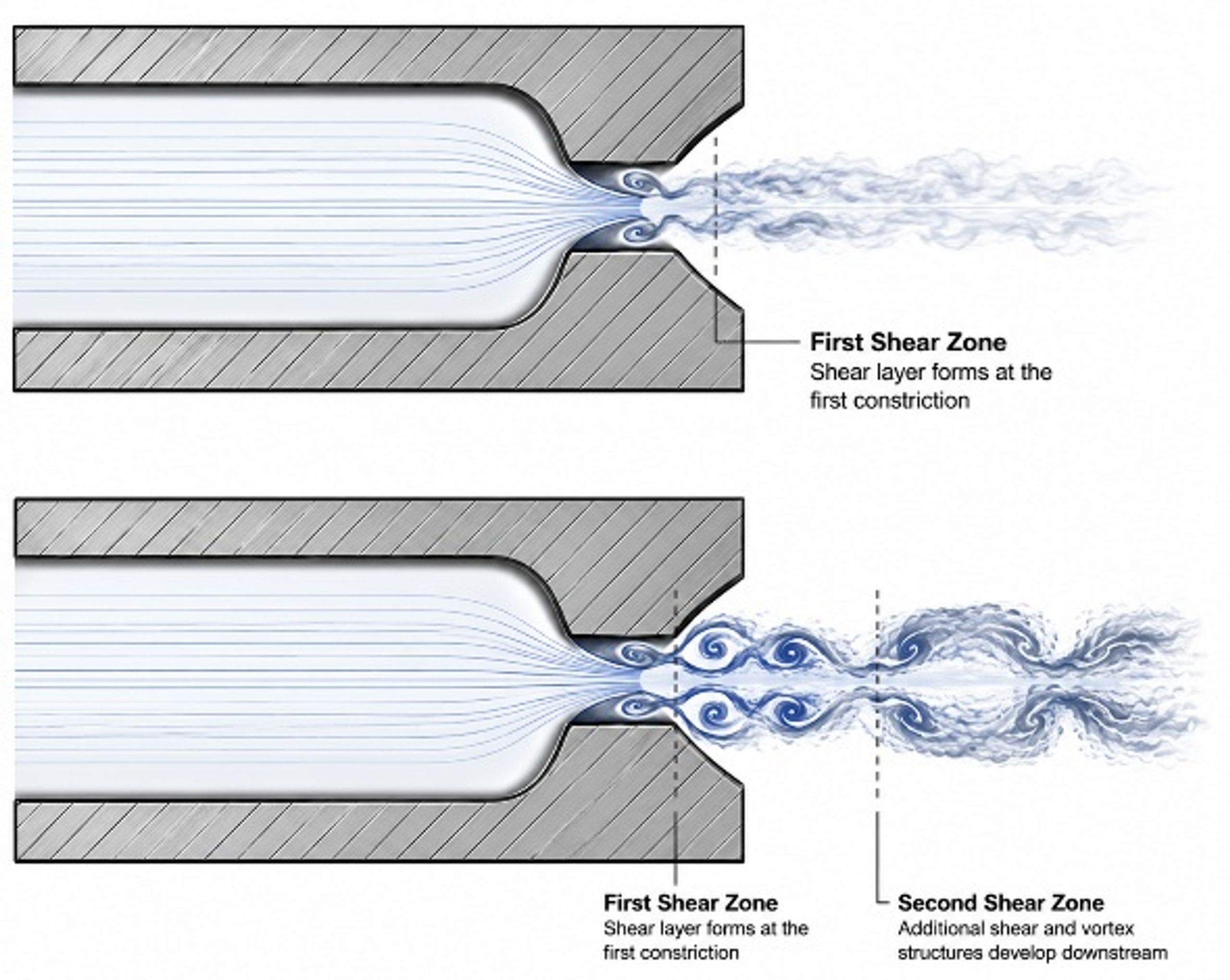
Figure 2.4. Jet forming nozzle with first and second shear zones [69].
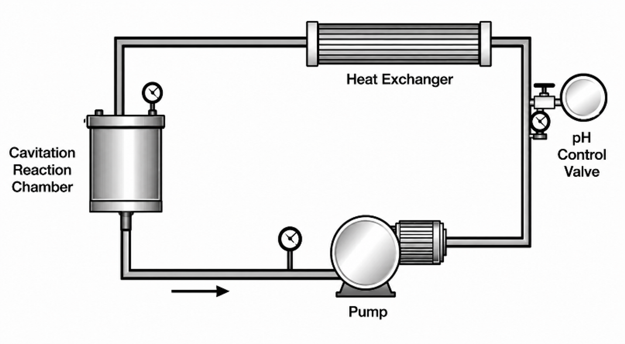
Figure 2.5. Recirculating cavitation treatment loop with reaction chamber, pump, heat exchanger, and pH control [69].
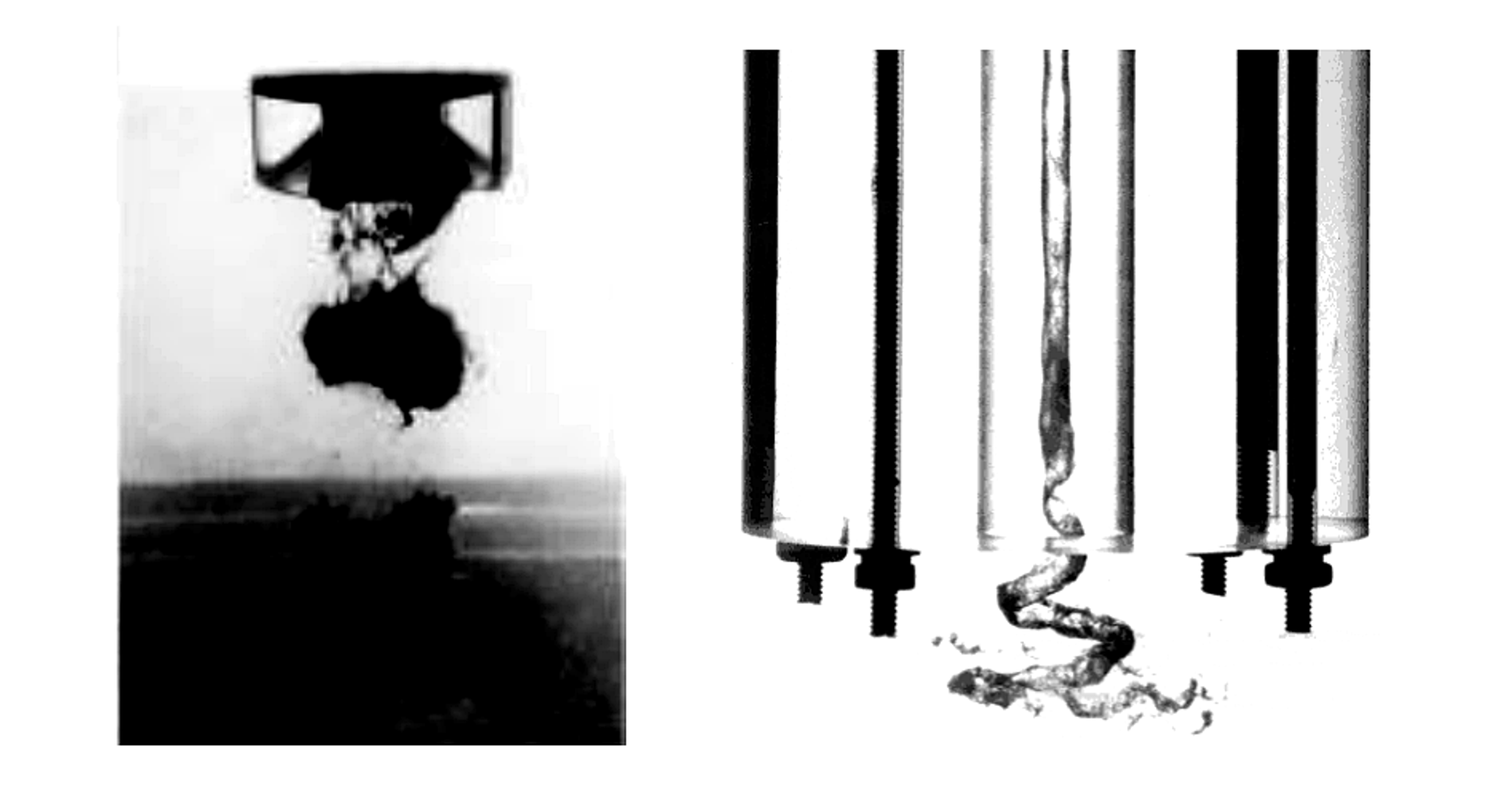
Figure 2.6. Stroboscopic views of resonant and swirling cavitating jets [17].
Kalumuck and Chahine used recirculating jet loops and multistage orifice plates with downstream stagnation surfaces to oxidize dilute p-nitrophenol. Under the reported experimental conditions, submerged cavitating jets provided approximately two orders of magnitude greater energy efficiency than the ultrasonic comparison. The authors attributed this result to broader cavitation distribution and the relatively high efficiency of hydraulic pumps. The reported ratio is study specific and should not be generalized to all reactors or contaminants [56].
Backpressure is an active design variable. Insufficient downstream pressure recovery can produce a stable or supercavitating vapor region with weak collapse. Excessively abrupt recovery, particularly on a vulnerable wall, can increase erosion, noise, and vibration. Productive operation therefore requires control of both inception and collapse, including the axial position of cloud shedding and the distance between collapse zones and sensitive equipment surfaces [9,10,15,56].
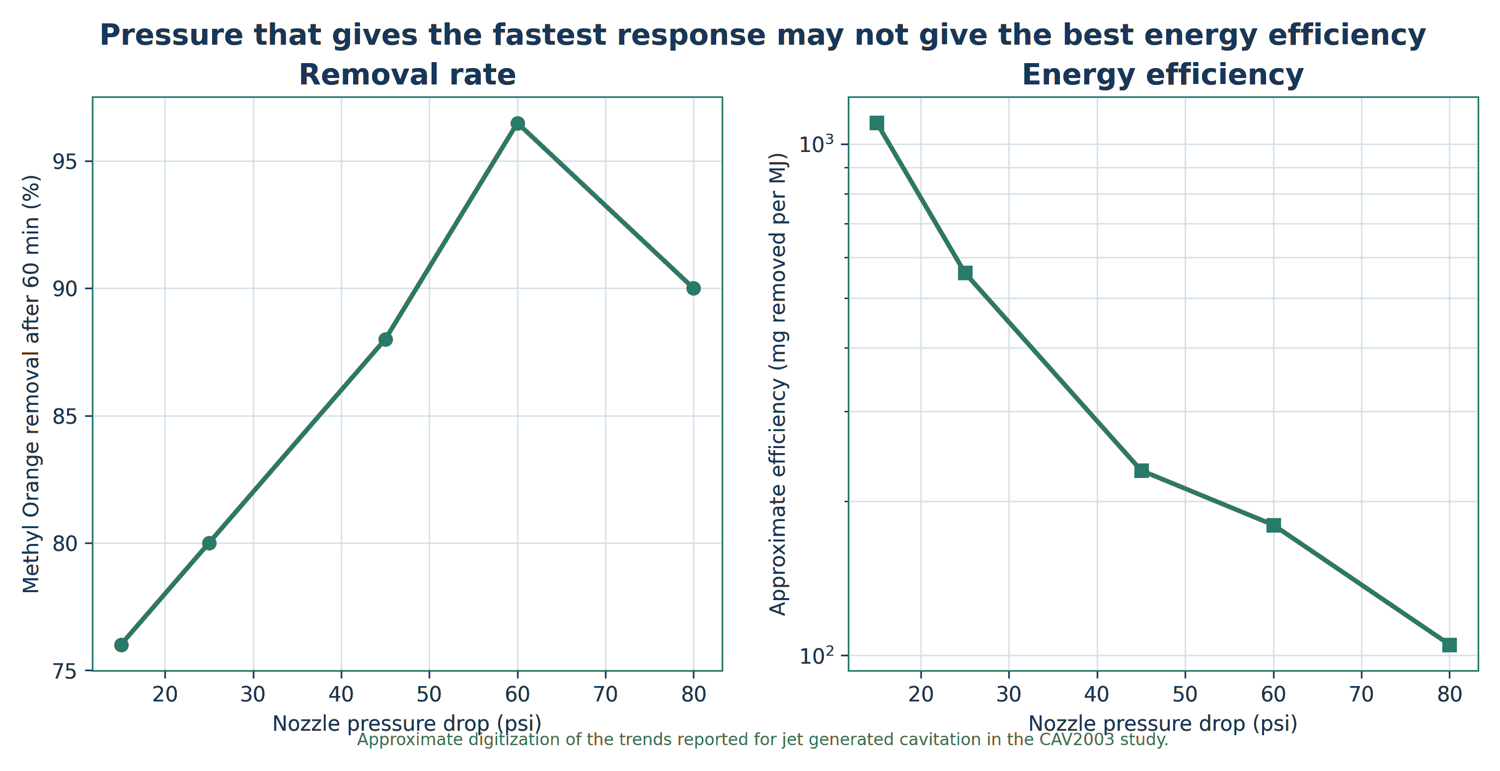
Figure 2.7. Pressure can accelerate contaminant removal while reducing hydraulic energy efficiency [17].
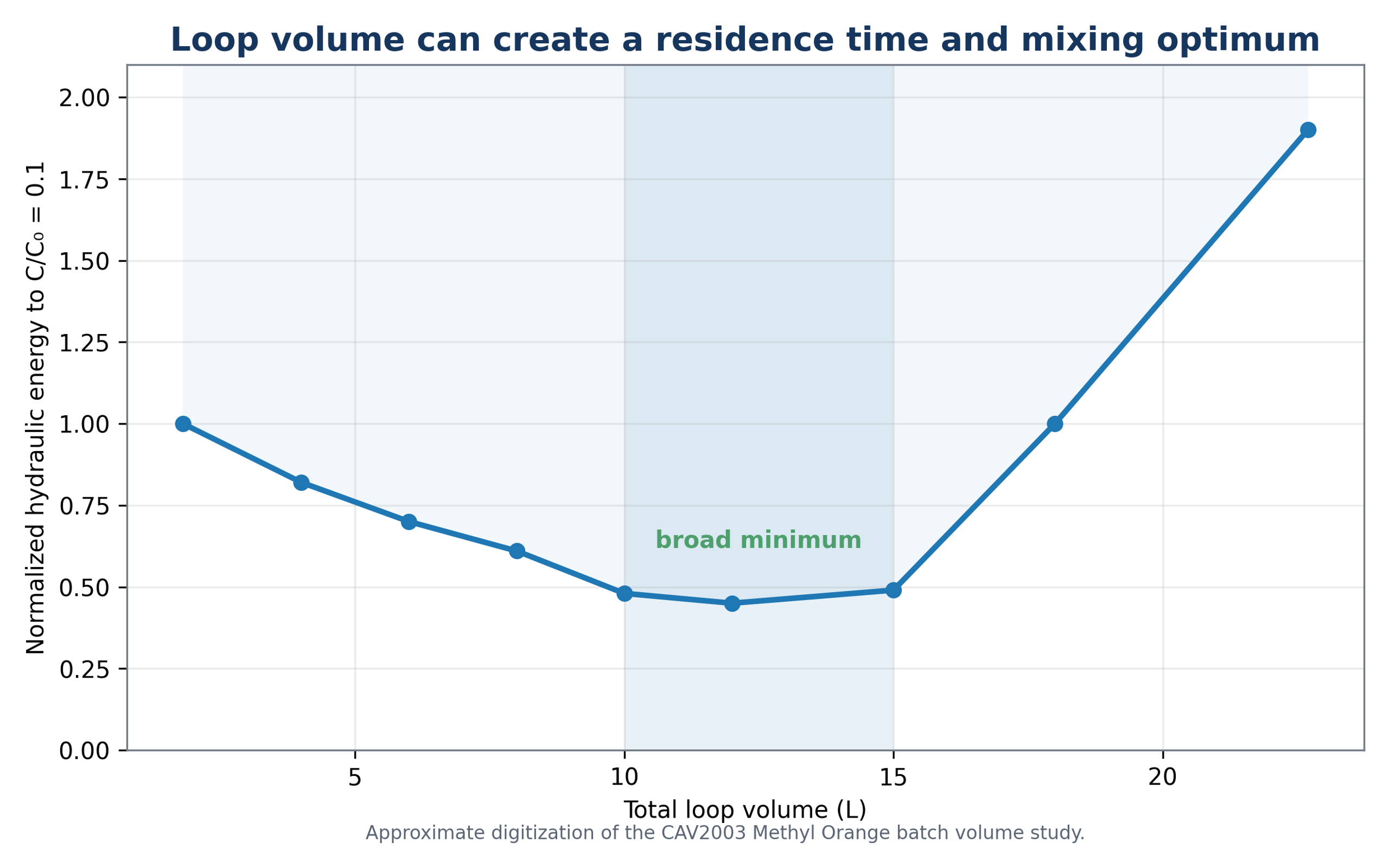
Figure 2.8. Effect of recycle loop volume on the energy required for one order of magnitude methyl orange reduction [17].
3 Hydrodynamic Cavitation for Wastewater Treatment
3.1 Position in the Treatment Train
Hydrodynamic cavitation is best applied as a targeted unit operation rather than as a universal replacement for primary treatment, biological treatment, or separation processes. In municipal treatment, HC may be positioned before biological treatment to improve biodegradability, after biological treatment to reduce micropollutants and residual pathogens, or in a sludge side stream. In industrial treatment, it may pretreat concentrated or toxic streams, intensify oxidant contact, or provide polishing before reuse. Placement should be determined by the dominant process limitation, including mass transfer, biodegradability, particle accessibility, toxicity, or microbial risk [1-8].
Published studies indicate that performance measured for a single compound in clean water can overestimate treatment in real effluent. Carbonate, bicarbonate, chloride, natural organic matter, suspended solids, oils, surfactants, and coexisting contaminants can consume radicals and modify bubble dynamics. Conversely, suspended solids and gas bubbles can supply nuclei and increase the number of cavitation events. These competing effects make matrix specific testing necessary [1,2,4,8].
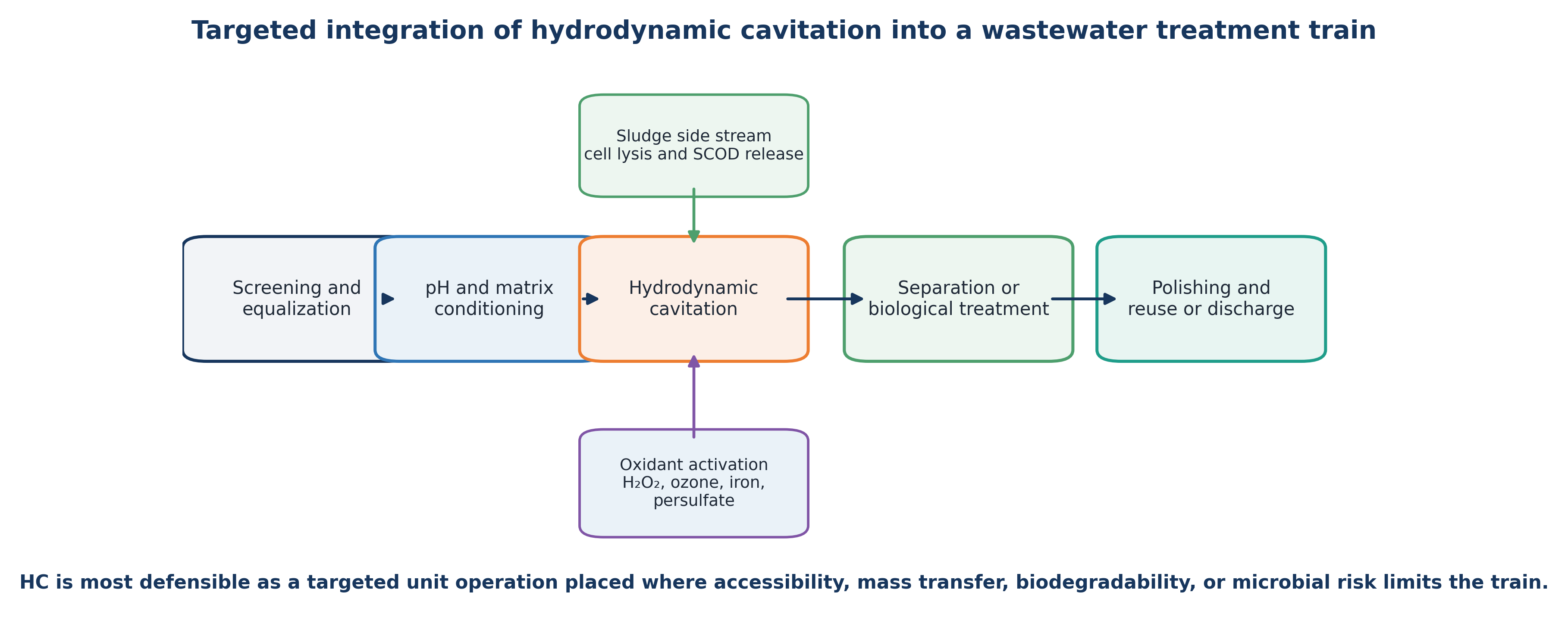
Figure 3.1. Targeted positions for hydrodynamic cavitation in municipal and industrial wastewater treatment trains [11].
3.2 Model Compounds and Optimization of Hydraulic Severity
The p-nitrophenol study by Capocelli et al. illustrates a nonmonotonic pressure response. In a 1.5 L recycle apparatus with a transparent Venturi, inlet pressure was varied from 0.2 to 0.7 MPa. Removal rate and energy efficiency were optimized near 0.4 to 0.45 MPa, corresponding to a reported cavitation number close to 0.25. At 0.45 MPa, the observed first order rate constant was approximately 1.13 × 10⁻² min⁻¹ and EEO was 66.7 kWh m⁻³ per order [16]. Further pressure increase raised hydraulic demand and altered cavity behavior without a proportional chemical benefit.
This result illustrates a broader design principle. Weak cavitation produces too few intense collapse events, whereas developed cavitation can provide a large population of productive events. At excessive severity, vapor shielding, coalescence, long attached cavities, choked flow, and nonproductive energy dissipation can reduce the fraction of input energy converted to useful collapse. The operating optimum should therefore be determined experimentally using a chemical or biological response together with an energy normalized metric.
3.3 Real Industrial Wastewater, Landfill Leachate, and Nutrient Removal
Studies in real wastewater demonstrate both the potential and the limitations of standalone HC. Korniluk and Ozonek treated mature landfill leachate in a recycle loop with a four slot orifice reactor operating at approximately 7 bar, 46.5 L min⁻¹, and a total liquid volume of about 40 L. After 30 minutes, COD decreased by 6.7% and TOC by 5.1%, while temperature increased by approximately 11 °C [19]. These modest removals are consistent with the high concentration and refractory character of mature leachate. Under such conditions, HC is more plausibly used as pretreatment or for oxidant activation than as the sole mineralization process.
Badve and coworkers studied actual wood finishing wastewater with an initial COD of approximately 38,000 mg L⁻¹ and pH 6.18. The rotating cavitator used a rotor with 204 surface indentations. COD reduction depended on rotor speed, residence time, and peroxide dose. The study reported an optimum near 2200 rpm and an optimum H₂O₂ loading near 5 g L⁻¹. Under the tested conditions, HC alone produced substantial COD reduction, while the optimized HC peroxide process increased cavitational yield by approximately 46% [20]. Higher peroxide loading reduced the benefit, which is consistent with radical scavenging.
In an industrial advanced Fenton study, a 25 L recirculating hydrocavitator was coupled with zero valent iron and hydrogen peroxide. The feed was a complex substituted phenolic effluent with reported pH 1.7, COD of about 42,000 mg L⁻¹, and TOC of about 14,000 mg L⁻¹. Under otherwise comparable conditions, TOC removal increased from about 50% at 500 psi to 52% at 1000 psi and 60% at 1500 psi. A 15 minute active treatment followed by storage also produced continued mineralization, indicating that cavitation initiated chemistry that persisted after hydraulic exposure [70].
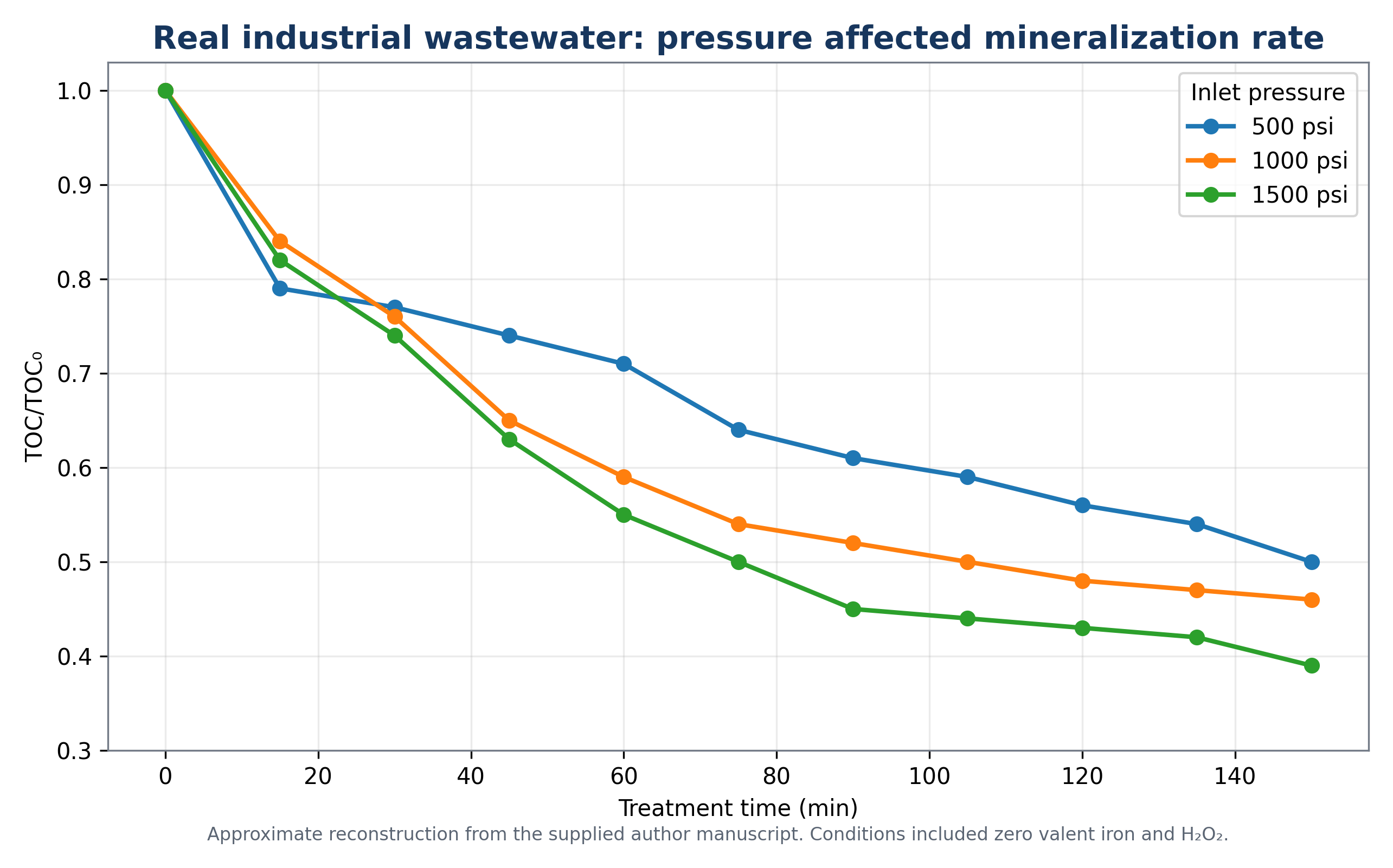
Figure 3.2. Effect of hydrocavitator inlet pressure on total organic carbon mineralization in industrial wastewater treated with heterogeneous advanced Fenton chemistry [70].
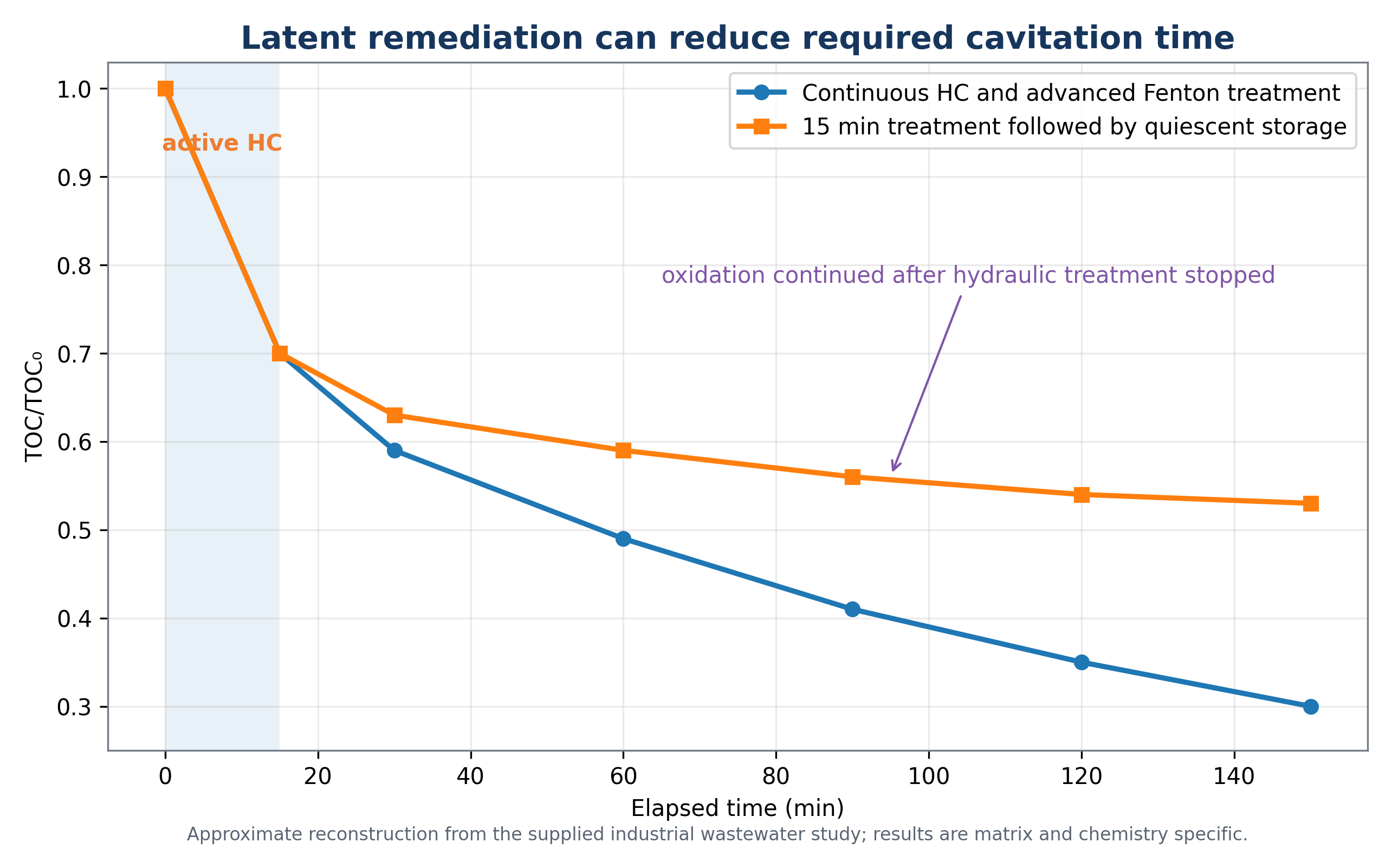
Figure 3.3. Continuous treatment and latent remediation after a short active cavitation period [70].
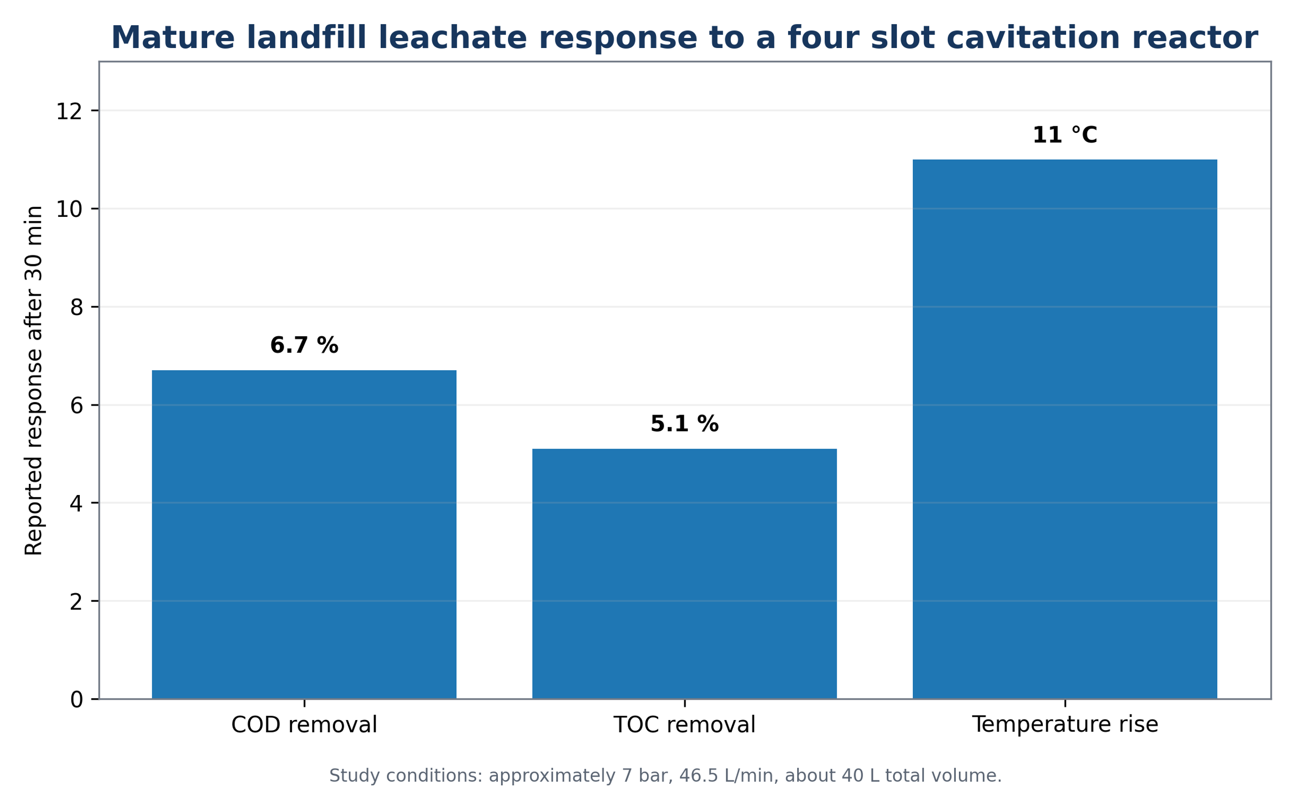
Figure 3.4. Response of mature landfill leachate during 30 minutes of recirculating hydrodynamic cavitation [19].
A separate phosphate removal study applied 20% calcium hydroxide slurry before HC to intensify precipitation and dispersion. Approximately 70% phosphate reduction was reported, with a jet nozzle producing the best result among the tested devices [26]. This application is based on physicochemical precipitation rather than radical oxidation and demonstrates that HC can improve dissolution, dispersion, nucleation, and contact efficiency even when oxidation is not the primary removal mechanism.
For micropollutant polishing, one liter of water containing six model pharmaceuticals was repeatedly passed through a narrow Venturi at initial pressures of 4, 5, and 6 bar in the presence of hydrogen peroxide. The 6 bar condition produced the highest reported removals, but response varied substantially among compounds, from approximately 45% for clofibric acid to 86% for naproxen [44]. A more recent study applied ozone assisted HC to antibiotic contaminated aquaculture seawater, illustrating the transition toward integrated gas liquid transfer, oxidant activation, and treatment train design rather than cavitation alone [49].
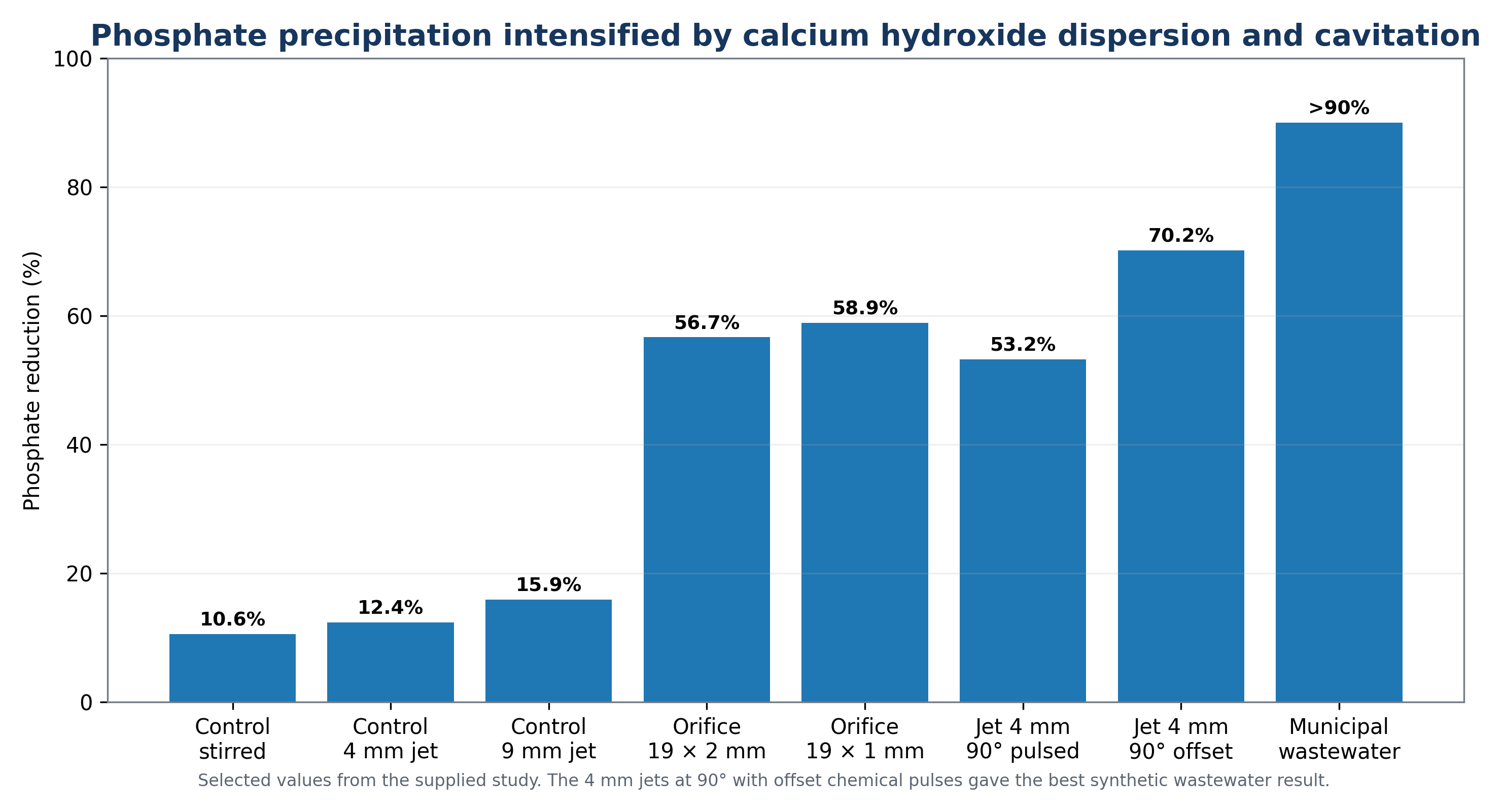
Figure 3.5. Phosphate reduction reported for mixing, orifice plate, and jet nozzle configurations using calcium hydroxide slurry [26].
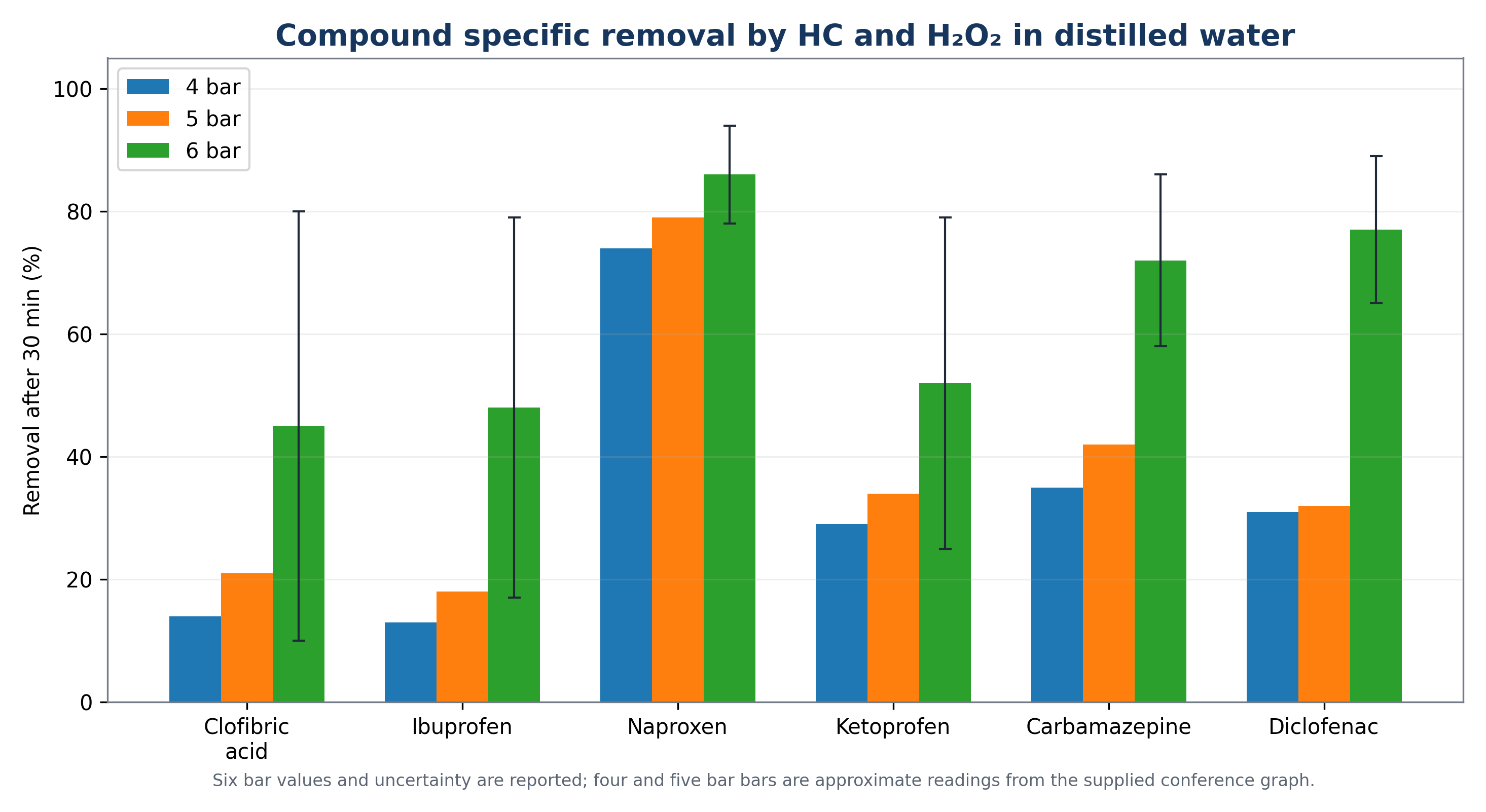
Figure 3.6. Removal of six pharmaceuticals after hydrodynamic cavitation with hydrogen peroxide at 6 bar [44].
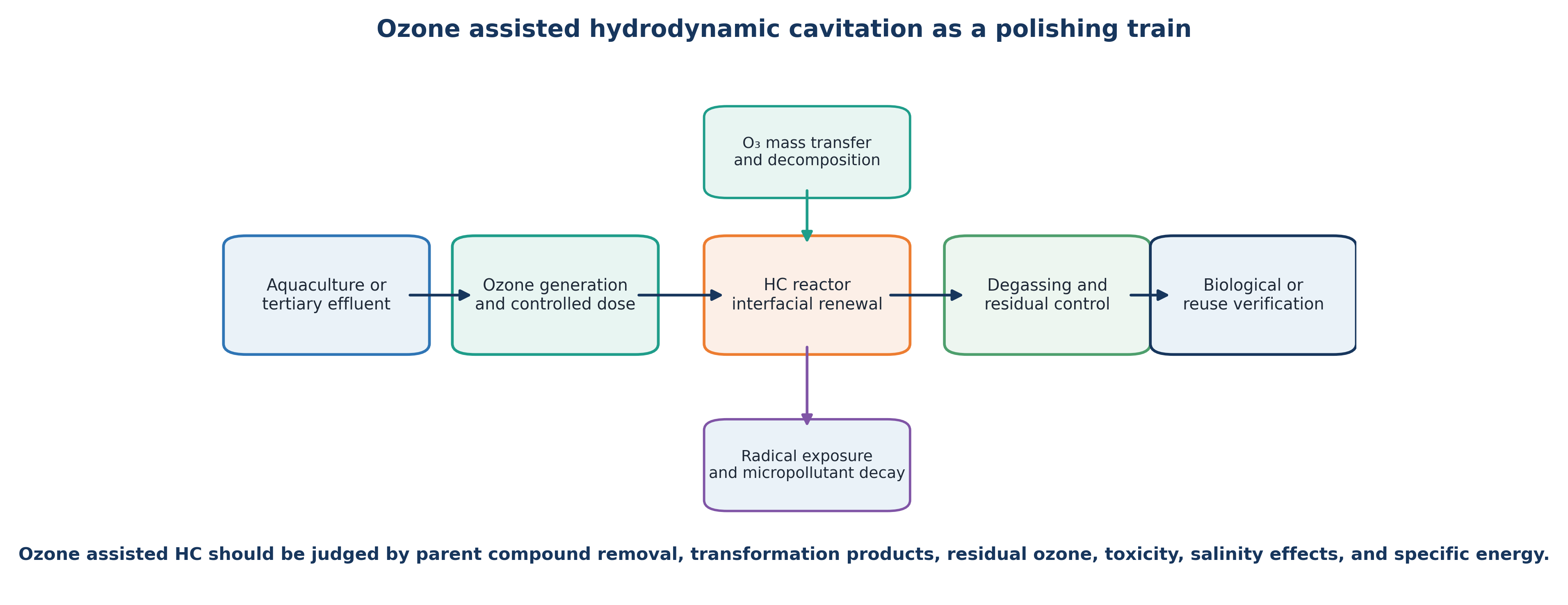
Figure 3.7. Conceptual ozone assisted hydrodynamic cavitation treatment train for antibiotic contaminated water [7,8,49].
Table 3.1. Representative HC wastewater treatment studies from the reviewed and recent literature.
| Matrix or target | Reactor and treatment | Representative result | Engineering interpretation |
|---|---|---|---|
| p Nitrophenol | Recycle Venturi, 0.2-0.7 MPa | Optimum near 0.4-0.45 MPa; EEO 66.7 kWh m⁻³ per order | Maximum pressure was not the optimum [16] |
| Landfill leachate | Four slot orifice, 7 bar, 30 min | COD 6.7%; TOC 5.1% | Standalone HC gave limited mineralization in a refractory matrix [19] |
| Wood finishing wastewater | Rotor stator with indentations, HC and H₂O₂ | COD reduction and yield improved at an optimum dose; yield +46% | Rotor speed, residence time, and oxidant dose must be jointly optimized [20] |
| 2,4-D herbicide | HC plus zero valent iron and H₂O₂ | Residual TOC about 30% after 20 min in the reported continuous treatment | Advanced Fenton chemistry supplied radicals beyond those generated by water alone [22] |
| 2-Chlorophenol | Venturi enhanced cavitation oxidation process | Higher H₂O₂ dose increased degradation, but efficiency favored mild cavitation and controlled injection | Fast treatment and minimum energy can require different operating points [21] |
| Phosphate containing wastewater | Ca(OH)₂ slurry plus orifice or jet HC | About 70% phosphate reduction | HC intensified precipitation and solids contact [26] |
| Wastewater pharmaceuticals | HC with H₂O₂, ozone, Fenton, persulfate, plasma, or catalysts | Performance depends strongly on compound and water matrix | Hybrid selection should be driven by reaction domain and scavenging [45-47] |
The landfill leachate experiment also demonstrates the importance of recording temperature as a response variable. During 30 minutes of recirculation, liquid temperature increased by approximately 11 °C while COD and TOC decreased by only 6.7% and 5.1%, respectively. Most absorbed hydraulic energy was therefore expressed as bulk heating rather than deep mineralization. Evaluation based only on removal percentage would not capture this energy partitioning [19].
In concentrated wastewater with high radical scavenging capacity, a modest change in COD or TOC does not necessarily indicate that pretreatment is ineffective. Molecular weight distribution, biodegradability, toxicity, color, volatile compounds, and downstream biological oxygen demand may change before extensive mineralization occurs. These secondary endpoints should be measured when HC is intended as pretreatment rather than as a final oxidation process.
3.4 Design Implications for Real Effluents
The treatment objective should be defined before operating conditions are selected. Parent compound removal is sufficient only when transformation products are known and acceptable. COD and TOC are required when bulk oxidation or mineralization is the objective. The biochemical oxygen demand to COD ratio, respirometry, or biochemical methane potential can quantify changes in biodegradability. Toxicity assays are required when reactive intermediates may form. Color removal and ultraviolet absorbance are useful supplementary indicators but can be misleading when chromophores are destroyed without corresponding carbon removal.
A staged treatment sequence is often preferable. Coarse solids or free oil can be removed first to avoid unnecessary hydraulic duty. HC can then be applied within a concentration and pH range that provides access to the target. Biological treatment can remove biodegradable products, and final polishing can address residual micropollutants or microbial risk. This approach confines the high intensity step to locations where it contributes measurable value and avoids attempting to mineralize the entire organic load by cavitation alone [23-25].
3.5 Equipment Selection and Hydraulic Integration
Reactor selection must account for wastewater characteristics and system integration. Low solids pharmaceutical polishing can use narrow Venturi or orifice passages with controlled oxidant injection. Fibrous, oily, or particulate streams require larger flow paths, maceration, flushing provisions, or dynamic devices with solids tolerant clearances. Sludge service requires positive displacement or progressive cavity pumping, controlled temperature rise, and grit protection. Highly corrosive industrial effluent may require lined piping, compatible elastomers, and replaceable cavitation elements.
The controlled cavitation equipment described by Nicholas and Vella used pressure equalization chambers and opposed truncated nozzles to form a collision region within a central chamber. A transparent demonstration chamber allowed visualization of the cavitation cloud. The arrangement demonstrates how equalized feed pressure and opposed flow can localize collapse without relying on a single downstream wall. Because the reported sludge benefits were obtained in a developer affiliated pilot study, the equipment photographs provide useful design information, whereas performance claims require independent verification at the intended duty [59].
A minimum instrumentation package should measure upstream and downstream pressure, flow rate, liquid temperature, motor or pump power, and treatment time. Hybrid processes should additionally measure pH, oxidant dose, residual oxidant, dissolved oxygen or ozone transfer, and off gas. Sampling must distinguish instantaneous pass performance from the cumulative response of a recycle tank. Loop volume, dead volume, bypass flow, cooling duty, and nominal turnover count should be reported.
Table 3.2. Wastewater matrix and equipment selection considerations.
| Matrix or objective | Preferred reactor features | Main risks | Essential controls |
|---|---|---|---|
| Low solids micropollutant polishing | Venturi, orifice, vortex, or jet with controlled oxidant contact | Radical scavenging, overdosage, low single pass conversion | Pressure, flow, pH, oxidant residual, EEO, transformation products |
| Concentrated industrial wastewater | Recycle loop, staged oxidation, heat rejection, sampling between stages | Bulk heating, incomplete mineralization, toxicity of intermediates | COD, TOC, biodegradability, toxicity, temperature, specific energy |
| Waste activated sludge | Large passages or rotational device, macerator, positive displacement pumping | Grit wear, plugging, excessive solubilization, foaming changes | SCOD, particle size, viscosity, BMP, torque, temperature |
| Oily or emulsified wastewater | Jet, vortex, or rotor with downstream flotation or separation | Stable emulsification when separation is intended | Droplet size, oil removal, gas transfer, flotation performance |
| Precipitation and nutrient removal | Rapid dispersion and nucleation followed by clarification or filtration | Fine solids carryover and scaling inside the reactor | pH, reagent stoichiometry, particle size, settling, pressure loss |
| Disinfection and reuse | Repeated pressure cycles with validated biological endpoint | Sublethal injury, regrowth, shielding by solids | Culture and infectivity assays, turbidity, temperature, LRV, residual control |
4 Sludge Pretreatment and Anaerobic Digestion
4.1 Hydrolysis Limitation and Disintegration Mechanisms
Waste activated sludge contains flocs, extracellular polymeric substances, microbial cells, cell debris, and slowly degradable particulate organic matter. Hydrolysis is commonly the rate limiting step in anaerobic digestion. HC pretreatment can reduce floc and particle size, damage cell walls, release soluble COD, expose intracellular material, and increase the surface area available to hydrolytic and fermentative microorganisms [5,27-32]. Because primary sludge is generally more readily biodegradable, its relative response may be smaller than that of secondary sludge.
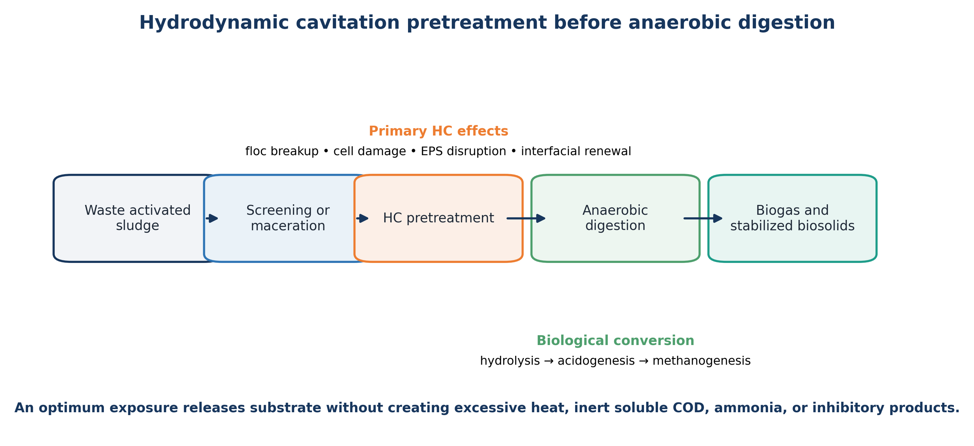
Figure 4.1. Hydrodynamic cavitation pretreatment before anaerobic digestion [11].
The degree of sludge disintegration, DDCOD, can be calculated using Equation (4.1):
DDCOD is the degree of disintegration based on soluble chemical oxygen demand. SCODt is soluble COD after treatment, SCOD₀ is the initial soluble COD, and SCODmax is a reference maximum obtained by a defined chemical or thermal method. Because the reference method determines the denominator, it should be reported explicitly.
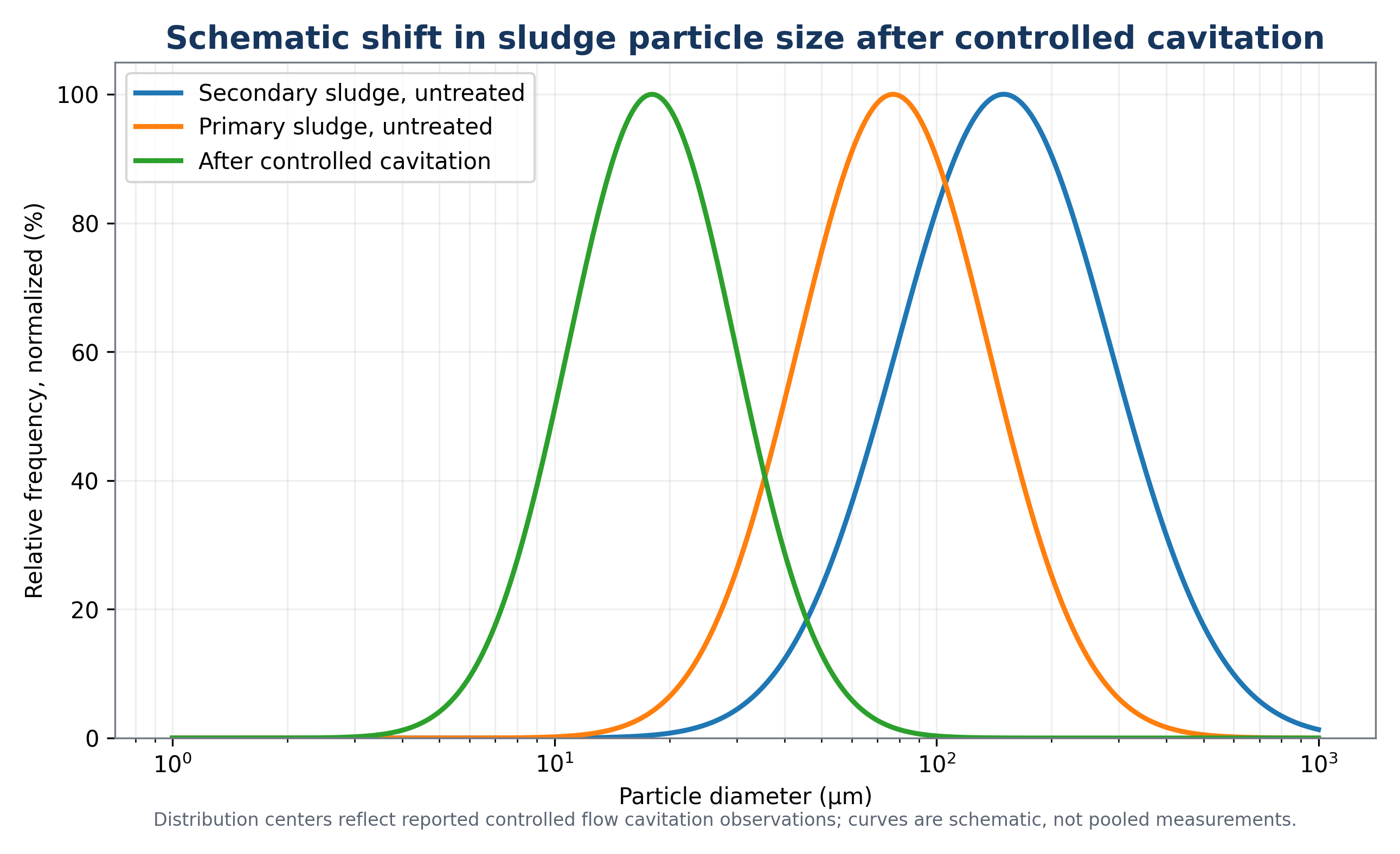
Figure 4.2. Schematic shift in sludge particle size distribution after controlled cavitation. The representative centers and treated size range reflect the controlled flow cavitation observations [27,28].
4.2 Methane Yield, Severity Optimum, and Excessive Treatment
Methane yield enhancement can be calculated using Equation (4.2):
Early controlled flow cavitation work summarized by Michel and Kozyuk reported narrower particle size distributions, typical methane yield improvements of 20% to 30%, and lower residual digested solids in the cited applications [5,27,28]. Grübel and Suschka combined mild alkalization near pH 9 with HC. Under the reported conditions, the hybrid treatment increased soluble organic release and produced 22% to 27% more biogas than conventional digestion [29]. The alkaline step weakened cell walls and flocs, while HC supplied shear, shock, mixing, and additional disintegration.
More recent results reinforce the existence of a treatment severity optimum. Abdelrahman et al. treated waste activated sludge at upstream pressures of 0.83 and 1.72 MPa. Methane yields were 128.4 and 119.1 mL CH₄ g⁻¹ VS, respectively, compared with 98.3 mL CH₄ g⁻¹ VS for the control. The lower pressure condition produced the largest increase, 30.6% [30]. A study by Son et al. using an advanced rotational HC reactor also found that excessive treatment could reduce biogas yield, whereas optimized treatment improved overall energy efficiency [31].
Table 4.1. Selected sludge pretreatment evidence and scale up implications.
| Study or system | Treatment | Reported outcome | Implication |
|---|---|---|---|
| Controlled flow cavitation [27,28] | Repeated flow through exposure | Secondary sludge distribution centered near 150 μm shifted below about 22 μm | Particle accessibility and hydrolysis can be improved without complete solubilization |
| Hybrid alkali HC [29] | Mild NaOH conditioning and developed Venturi cavitation | Higher SCOD release; biogas increased about 22-27% | Chemical weakening and mechanical disintegration can be synergistic |
| Flow pattern study [30] | Orifice HC at 0.83 and 1.72 MPa | Methane 128.4 and 119.1 versus 98.3 mL CH₄ g⁻¹ VS control | Lower pressure produced the best biological result |
| Advanced rotational HC [31] | Rotor based sludge disintegration | Optimized treatment improved digestibility and energy efficiency; excessive treatment was detrimental | Severity must be optimized against biological response, not only SCOD |
| Semi industrial rotating device [32] | Scale up to 500 L sludge pig slurry treatment | Specific solubilization energy decreased with scale | Rotational HC can benefit from scale when hydraulic duty is managed |
4.3 Quantitative Indicators of Sludge Disintegration
Machnicka, Grübel, and Suschka treated 25 L portions of activated sludge in a recycle system using a 1.2 mm nozzle and a pump pressure of approximately 12 bar. Soluble COD increased from about 42 to 326 mg L⁻¹ during 90 minutes of treatment, while the reported degree of disintegration increased from approximately 14% at 15 minutes to 54% at 90 minutes. The largest incremental increase occurred during the first 30 minutes, indicating that exposure time should be optimized against diminishing returns in solubilization [57].
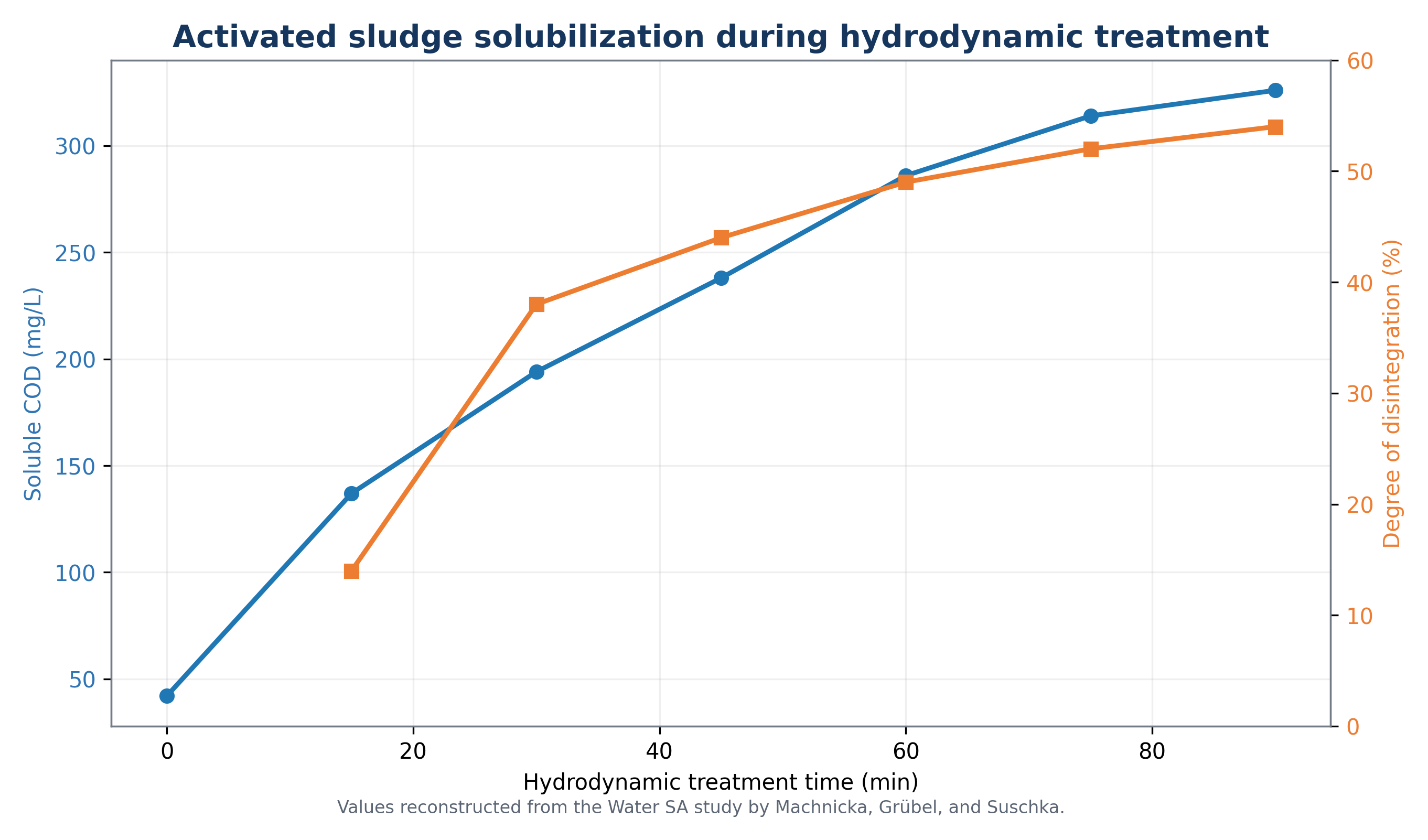
Figure 4.3. Soluble chemical oxygen demand release and degree of disintegration during hydrodynamic treatment of activated sludge [57].
Soluble COD is a useful process indicator but is not a complete measure of digestion benefit. Solubilized material may include readily fermentable substrate, slowly degradable macromolecules, inert soluble compounds, or inhibitory products. Pretreatment value should therefore be confirmed using methane yield, volatile solids destruction, dewaterability, ammonia release, viscosity, and the stability of the anaerobic microbial community.
In the same study, addition of disintegrated sludge at 10%, 20%, and 30% of fermenter volume increased reported biogas production by about 22%, 95%, and 131%, respectively, relative to the control. These batch responses indicate that the released substrate was biologically accessible under the test conditions. They should not be transferred directly to full scale continuous digesters because treated fraction, organic loading, solids retention time, inoculum adaptation, and the energy required for 90 minutes of recycle treatment differ substantially [57].
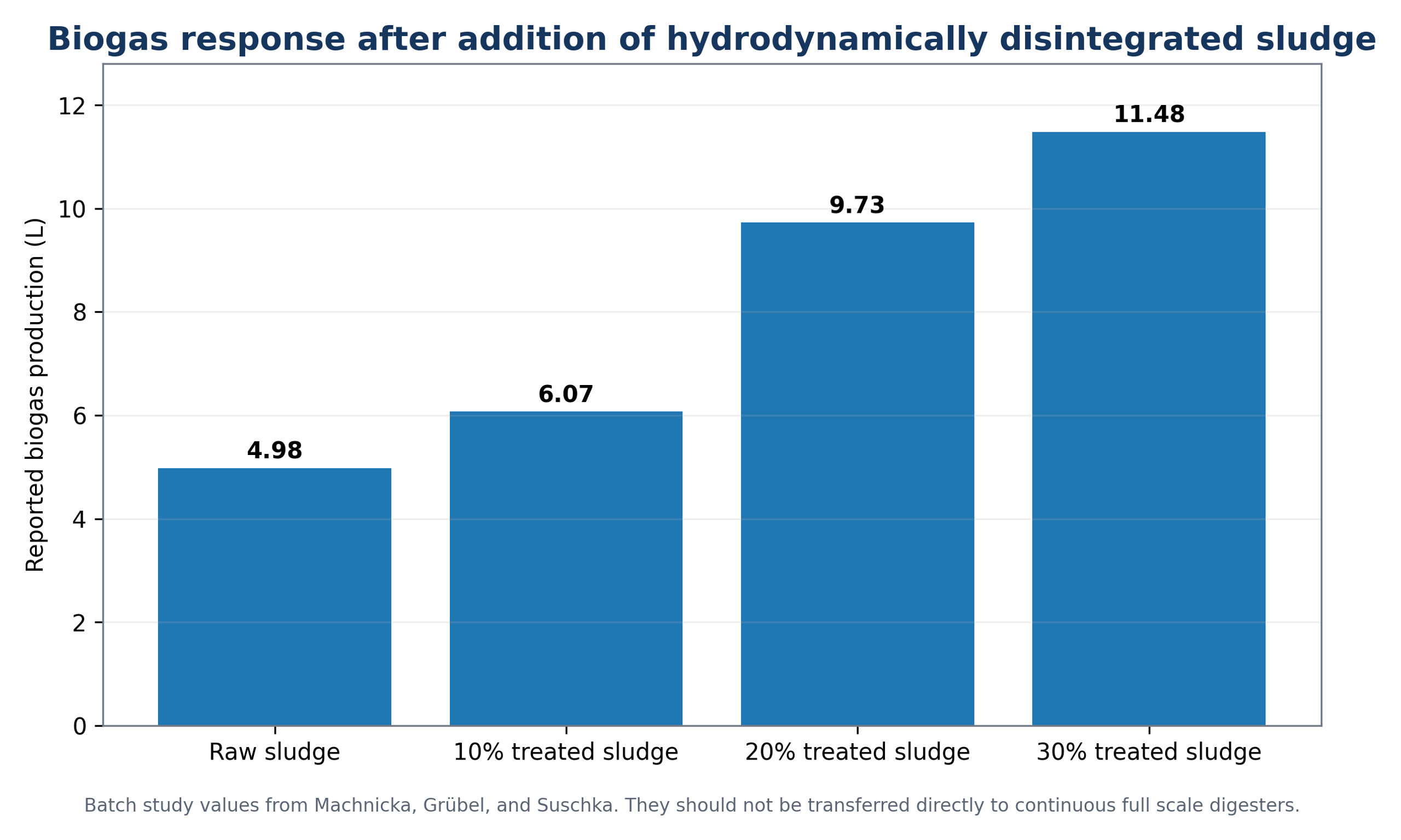
Figure 4.4. Reported biogas response after adding hydrodynamically disintegrated sludge to batch fermenters [57].
Optical microscopy from the APV INature process shows disruption of large agglomerates and filamentous structures after low pressure homogenization. Such images provide direct evidence of structural change, but microscopy should be combined with quantitative particle size and soluble organic measurements because individual visual fields may not represent the full sludge population [58].
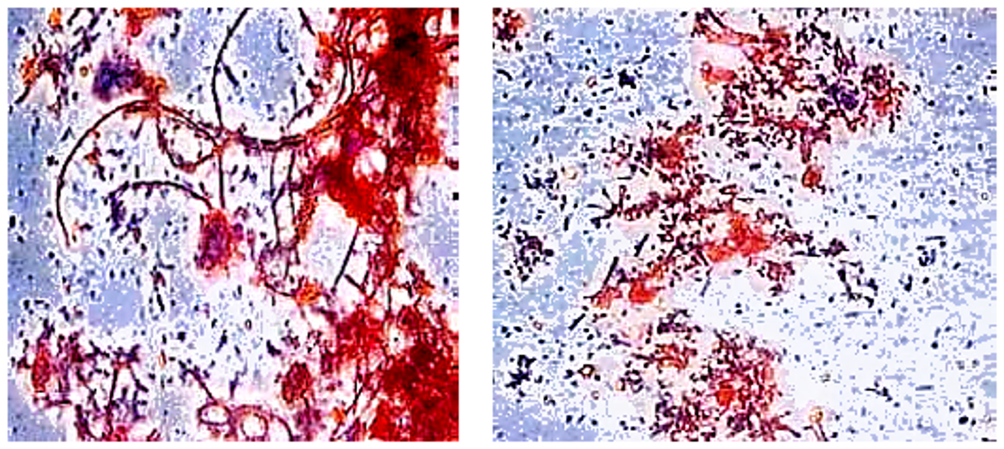
Figure 4.5. Activated sludge structure before and after cavitation [27,28].
4.4 Commercial and Full Scale Sludge Conditioning Systems
Commercial sludge systems commonly combine several unit operations rather than relying on a cavitation element alone. The APV INature configuration used an upstream macerator, a high pressure piston pump, and a low pressure homogenizing valve. The workshop paper identified approximately 150 bar and 5.5 kWh m⁻³ as the preferred operating point for the described installation. Reported particle size values decreased from 30 to 15 µm at X50 and from 80 to 32 µm at X90, with a claimed increase in available surface area greater than 100% [58].
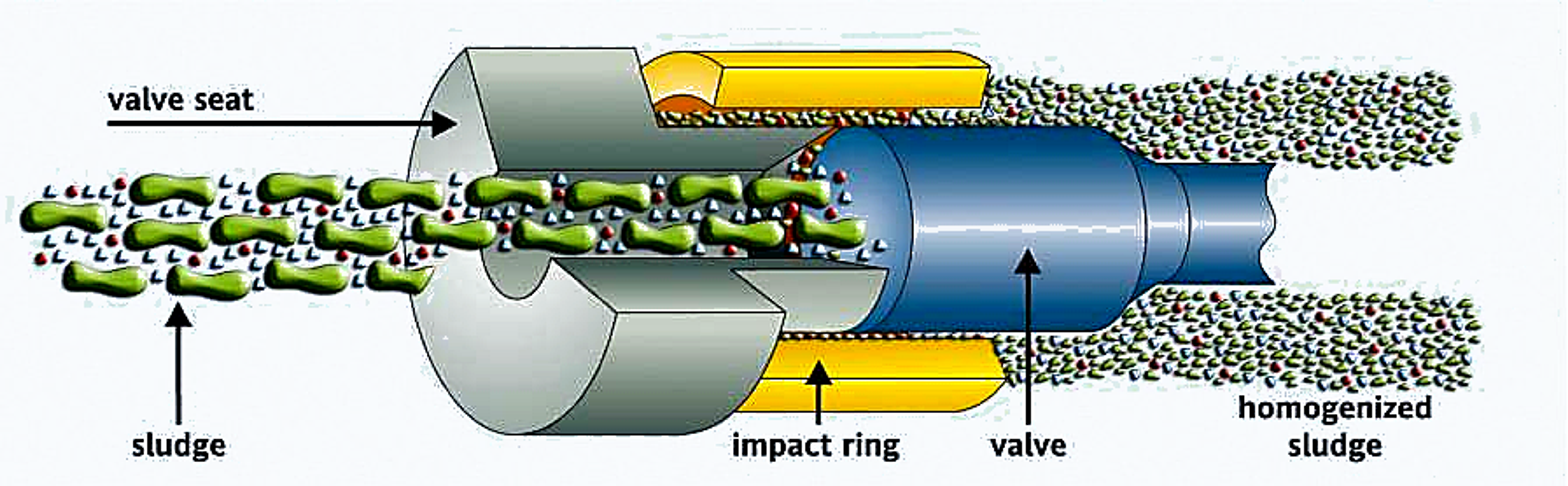
Figure 4.6. Low pressure homogenizing valve is used in the APV INature sludge treatment process [58].
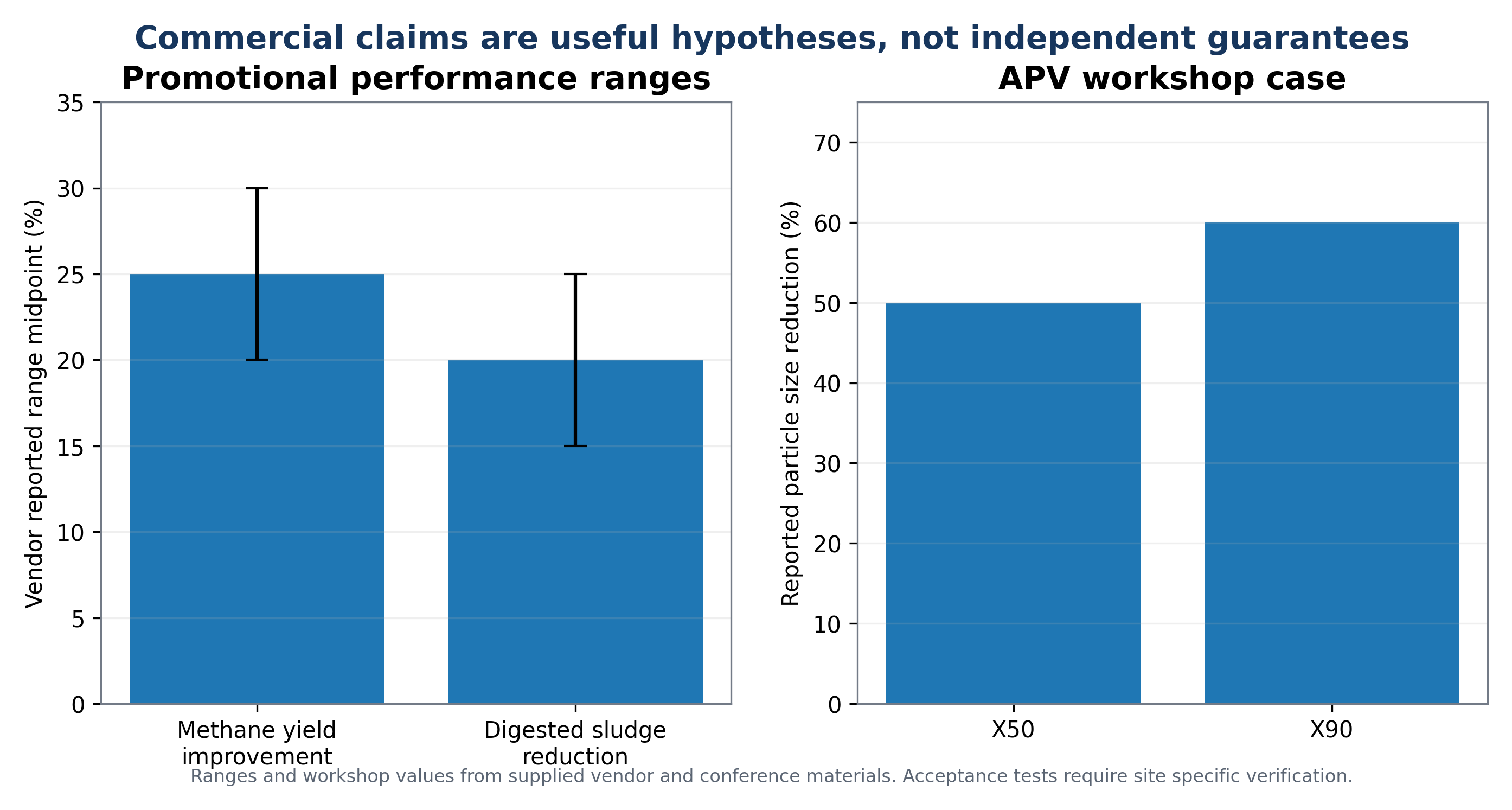
Figure 4.7. Reported anaerobic digestion benefits and particle size effects associated with controlled flow cavitation [60,66,71].
The VRTX study reported improvements in soluble COD, dewatering, suspended solids measures, sludge volume index, and particle size during pilot treatment of waste activated sludge [59]. The Siemens Crown process combined maceration, high speed mixing, pressurization, a disintegration nozzle, recirculation, and discharge to the digester. Technical literature reported biogas increases of up to 30% and post digestion solids reduction of up to 20% [60,66]. These values are useful for defining commercial performance hypotheses, but vendor associated results should be distinguished from independently controlled research data during design review.
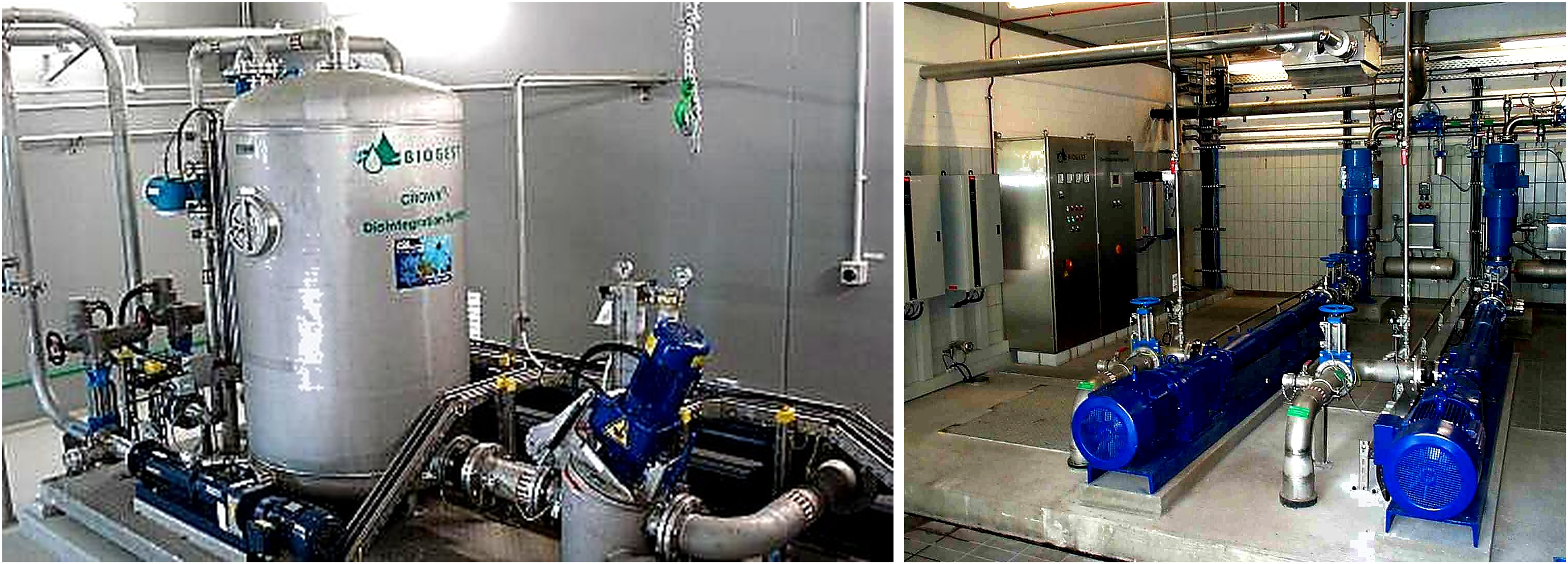
Figure 4.8. Crown sludge disintegration equipment and a full scale installation at Wiesbaden [60,65,66].
Full scale process value depends on the combined balance of additional methane production, reduced biosolids mass, improved cake solids, reduced foaming, and avoided external carbon addition. Potential losses include excessive electrical demand, maintenance, grit erosion, increased soluble refractory COD, and digester destabilization. Economic assessment should therefore be based on measured plant mass balances rather than on a single percentage improvement.
Table 4.2. Evidence hierarchy for sludge pretreatment design.
| Evidence class | Representative source | Strength | Limitation | Recommended design use |
|---|---|---|---|---|
| Controlled laboratory digestion | Machnicka et al. [57]; Abdelrahman et al. [30] | Direct comparison with control and defined treatment conditions | Small volume, batch digestion, matrix specific | Identify mechanisms, exposure optimum, and biological response |
| Pilot sludge treatment | Nicholas and Vella [59] | Real waste activated sludge and equipment operation | Developer affiliated study and limited long term data | Define solids handling, dewatering, and instrumentation needs |
| Workshop or commercial case study | Fulton [58]; Schmitt [65] | Plant scale equipment, operability, and economic context | Incomplete independent controls and variable reporting | Establish retrofit configuration and candidate performance range |
| Vendor technical literature | Siemens [60,66] | Equipment layout and claimed operating benefits | Marketing context and selective reporting | Develop hypotheses only; require guaranteed and independently verified acceptance tests |
| Recent peer reviewed rotational HC | Son et al. [31] | Modern reactor, BMP response, scale analysis, excessive treatment warning | Still requires site specific validation | Support advanced rotor selection and severity optimization |
5 Ballast Water Cavitation for Treatment
5.1 Regulatory and Process Context
Ballast water can transport bacteria, viruses, phytoplankton, zooplankton, larvae, cysts, and other organisms between ecosystems. The International Maritime Organization Ballast Water Management Convention establishes the D-2 performance standard for discharged ballast water. The phase in schedule for existing ships reached its final compliance date on 8 September 2024. The mandatory Code for Approval of Ballast Water Management Systems was adopted in 2018 and entered into force in October 2019, replacing the earlier G8 approval guidelines. Systems that use active substances remain subject to the additional environmental evaluation procedure associated with G9 [33-36].
As reported in the source material, by December 2025 the Convention had 101 Parties representing 93.73% of world merchant shipping tonnage [55]. Because the regulatory framework continues to evolve through the IMO experience building and review process, any commercial design, retrofit, or statement of approval status should be checked against current IMO, flag state, classification society, and port state requirements rather than inferred from historical literature.
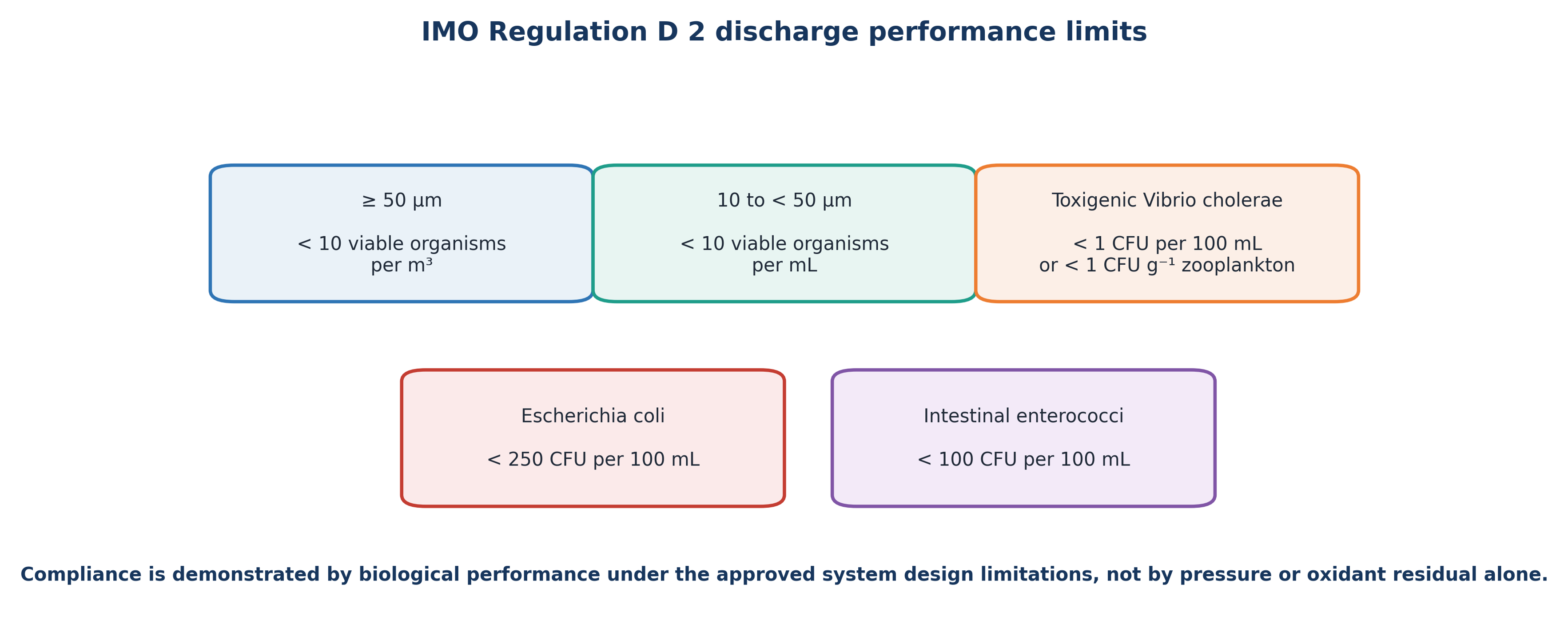
Figure 5.1. IMO Regulation D-2 ballast water discharge performance standard [34-36,55].
Table 5.1. IMO D-2 ballast water discharge limits.
| Organism or indicator | Maximum concentration in discharged ballast water |
|---|---|
| Viable organisms, minimum dimension ≥50 μm | <10 organisms m⁻³ |
| Viable organisms, 10 to <50 μm | <10 organisms mL⁻¹ |
| Toxigenic Vibrio cholerae O1 and O139 | <1 CFU 100 mL⁻¹ or <1 CFU g⁻¹ wet zooplankton |
| Escherichia coli | <250 CFU 100 mL⁻¹ |
| Intestinal enterococci | <100 CFU 100 mL⁻¹ |
5.2 Treatment Architecture and Biological Mechanisms
Ballast water systems normally combine unit operations because no single mechanism is equally effective for all organism size classes and water qualities. Filtration or hydrocyclonic separation removes larger organisms and protects downstream equipment. HC can then damage cells, improve oxidant contact, and expose organisms to repeated pressure and shear. An active substance, ozone, deoxygenation, or another disinfectant can provide residual control and suppress regrowth. Neutralization may be required before discharge when an active oxidant remains [33,37,38].
Hydrodynamic cavitation can inactivate organisms through membrane deformation, shear, microjet impact, pressure oscillation, shock waves, reactive species, and enhanced transport of chemical disinfectants. Large plankton and zooplankton are particularly susceptible to mechanical disruption, whereas bacteria and viruses may require repeated exposure or chemical assistance. Salinity, temperature, turbidity, dissolved organic carbon, organism type, and holding time influence the final response.
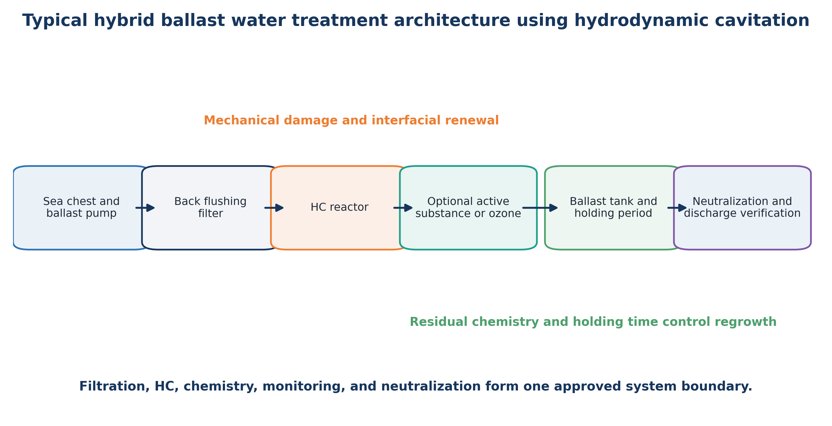
Figure 5.2. Typical hybrid ballast water treatment architecture incorporating filtration, hydrodynamic cavitation, oxidant generation, residual monitoring, and neutralization [33,37,38].
5.3 Historical Systems and the HyCator Case Study
The review by Cvetković et al. identified four type approved or commercial systems that incorporated HC as one treatment stage: JFE Ballast Ace, OceanSaver, FineBallast OZ, and Venturi Oxygen Stripping. Each system combined cavitation with filtration, chemical treatment, ozonation, nitrogen supersaturation, or deoxygenation [37]. These examples are historically important because they demonstrate commercial implementation of HC as part of a treatment train, but they should not be interpreted as evidence of current product availability or approval status.
Sangave, Mukherjee, and Pandit described a HyCator ballast water system that combined automatic back flushing filtration, controlled HC, and sodium hypochlorite generated by seawater electrolysis. The reported ballasting sequence used approximately 3 mg L⁻¹ total residual oxidant. Residual disinfectant was maintained during the holding period and was neutralized with sodium thiosulfate during deballasting to less than 0.1 mg L⁻¹. The reported tests met the selected D-2 biological endpoints in a single pass treatment train [38]. Because the paper was authored by personnel affiliated with the technology developer, the results should be treated as vendor associated performance evidence and supplemented by independent type approval data where available.
Yoshimura et al. evaluated mechanochemical ballast treatment using cavitating water jets with sodium hypochlorite. At a nozzle diameter of 3.1 mm, a flow rate of 30 L min⁻¹, and 5 mg L⁻¹ sodium hypochlorite, the authors reported complete extinction of the test plankton population. Ejector nozzles supported higher flow than the tested Venturi arrangement, indicating that chemical suction, nozzle pressure, and organism exposure should be designed as an integrated system [72].
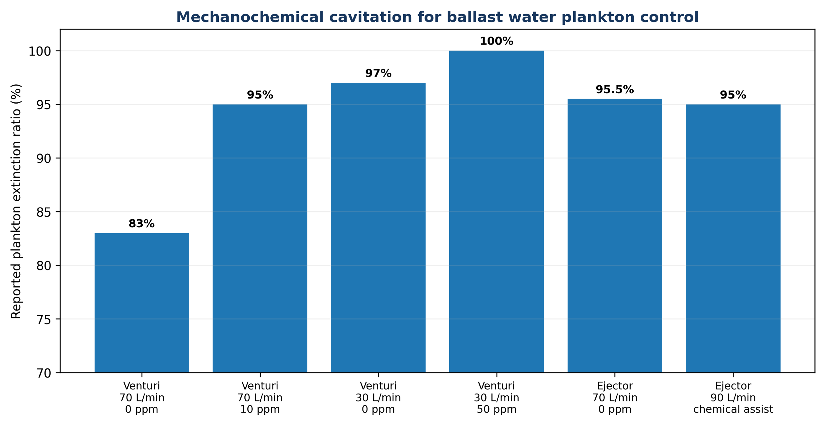
Figure 5.3. Plankton extinction reported for mechanochemical cavitation with sodium hypochlorite [72].
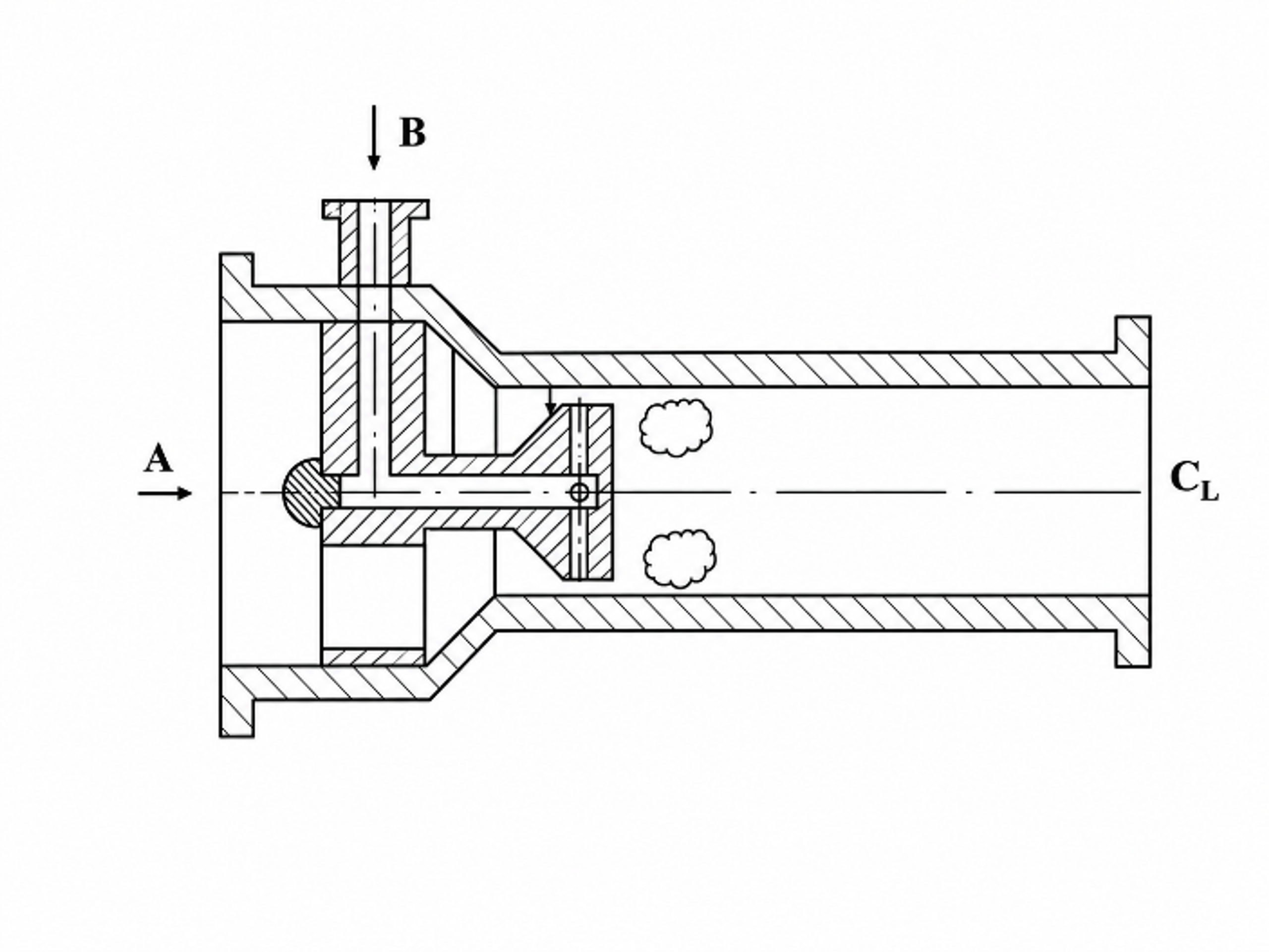
Figure 5.4. Water treatment cavitation device with chemical injection near the constriction [52].
5.4 Current Approval, Monitoring, and Verification Requirements
The HyCator process diagram illustrates the practical complexity of a physicochemical ballast water system. The ballasting line included filtration, a booster pump, a cavitation reactor, a side stream electrochlorination unit, total residual oxidant monitoring, hydrogen separation, and a ballast tank. During deballasting, sodium thiosulfate was metered into the discharge line and residual oxidant was measured before overboard discharge [38]. The cavitation reactor was therefore one controlled element within a larger safety and compliance system.
The source material states that the final D-2 implementation date for existing ships was 8 September 2024 and that, by December 2025, the Convention had 101 Parties representing 93.73% of world merchant shipping by tonnage [35,55]. It further reports that the IMO adopted revised G4 guidance in 2026 through resolution MEPC.409(84). The earlier G8 approval guidelines have been superseded by the mandatory BWMS Code, while systems using active substances remain subject to the G9 procedure [36].
A current design should document certified system design limitations, approved flow range, salinity and temperature envelope, turbidity limits, active substance dose, neutralization capacity, monitoring accuracy, and contingency procedures. Biological performance must be demonstrated using the prescribed organism size classes and indicator microbes rather than by pump pressure, cavitation number, or oxidant residual alone. Commissioning tests and operational sampling should also verify that bypasses, valve condition, sensor drift, and changing water quality do not compromise treatment.
Table 5.2. Ballast water management system verification items.
| Verification area | Required evidence | HC specific concern |
|---|---|---|
| Biological performance | D 2 organism size classes and indicator microbe limits under approved test conditions | Mechanical damage may not equal loss of viability; regrowth and assay method matter |
| System design limitations | Certified range for flow, salinity, temperature, UV transmittance or turbidity, and holding time | Cavitation pattern changes with vapor pressure, gas content, and backpressure |
| Active substances | IMO approval, dose control, byproduct evaluation, and neutralization | HC can intensify oxidant transfer and may alter residual demand |
| Mechanical integration | Pump, filtration, bypass protection, pressure relief, corrosion, and hydrogen safety where electrolysis is used | Pressure oscillation, erosion, noise, and gas release require engineered safeguards |
| Operational monitoring | Calibrated sensors, alarms, records, commissioning, and contingency actions | Pressure and power are surrogate indicators and cannot replace biological verification |
6 Remediation and Disinfection
6.1 Mechanical and Chemical Inactivation
Microbial inactivation by HC can proceed through mechanical and chemical pathways. Mechanical damage includes stretching and rupture caused by pressure oscillations, turbulent eddies, shear, shock waves, and microjets. Chemical damage includes oxidation of membranes, proteins, and nucleic acids by radicals or added oxidants. The relative contribution of these mechanisms depends on bubble size, collapse frequency, organism size and structure, and water chemistry [17,39-42].
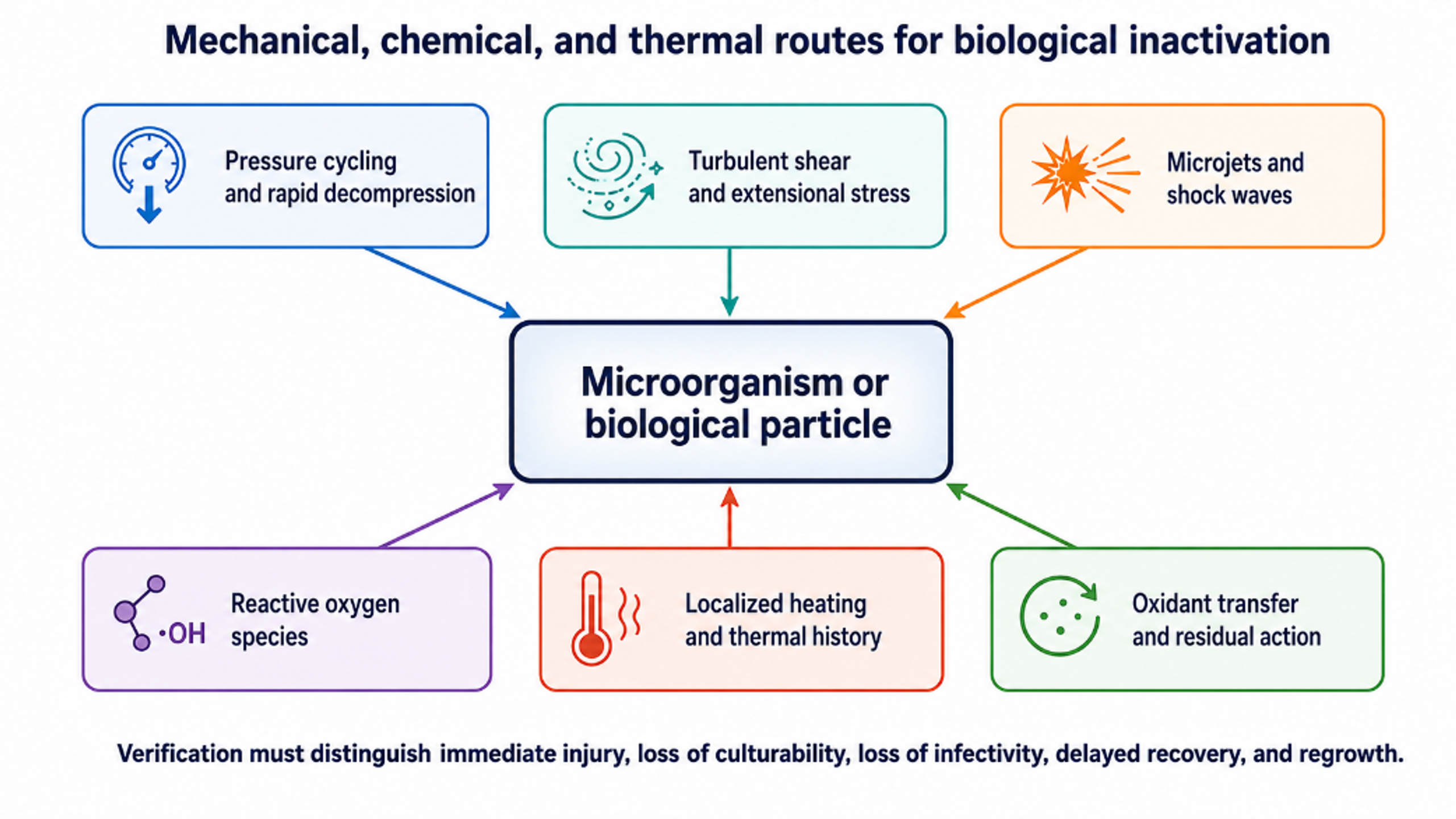
Figure 6.1. Mechanical, chemical, and thermal pathways that contribute to microbial inactivation by hydrodynamic cavitation [11].
Logarithmic reduction value is a useful biological metric and can be calculated using Equation (6.1):
N₀ and Nt are the initial and treated viable concentrations, respectively. For disinfectant assisted processes, the empirical Chick Watson relation in Equation (6.2) may be used to describe exposure:
CW is disinfectant concentration, n is an empirical exponent, and k is an inactivation constant. HC can alter the apparent value of k by improving micromixing, damaging protective structures, and renewing the cell liquid interface. The relation should not be extrapolated beyond the tested range because oxidant demand and organism susceptibility can change during treatment.
6.2 Jet Generated Cavitation and E. coli
Kalumuck et al. used submerged cavitating jets to oxidize contaminants and inactivate microorganisms. Their designs employed passive acoustic excitation, bluff bodies, or swirl to intensify cavitation at moderate pump pressure. The study reported multiple orders of magnitude reduction in E. coli and substantially greater energy efficiency than the compared ultrasonic configuration [17]. The authors also observed a pressure tradeoff: higher jet pressure accelerated treatment, whereas lower pressure could remove more contaminant per unit hydraulic energy.
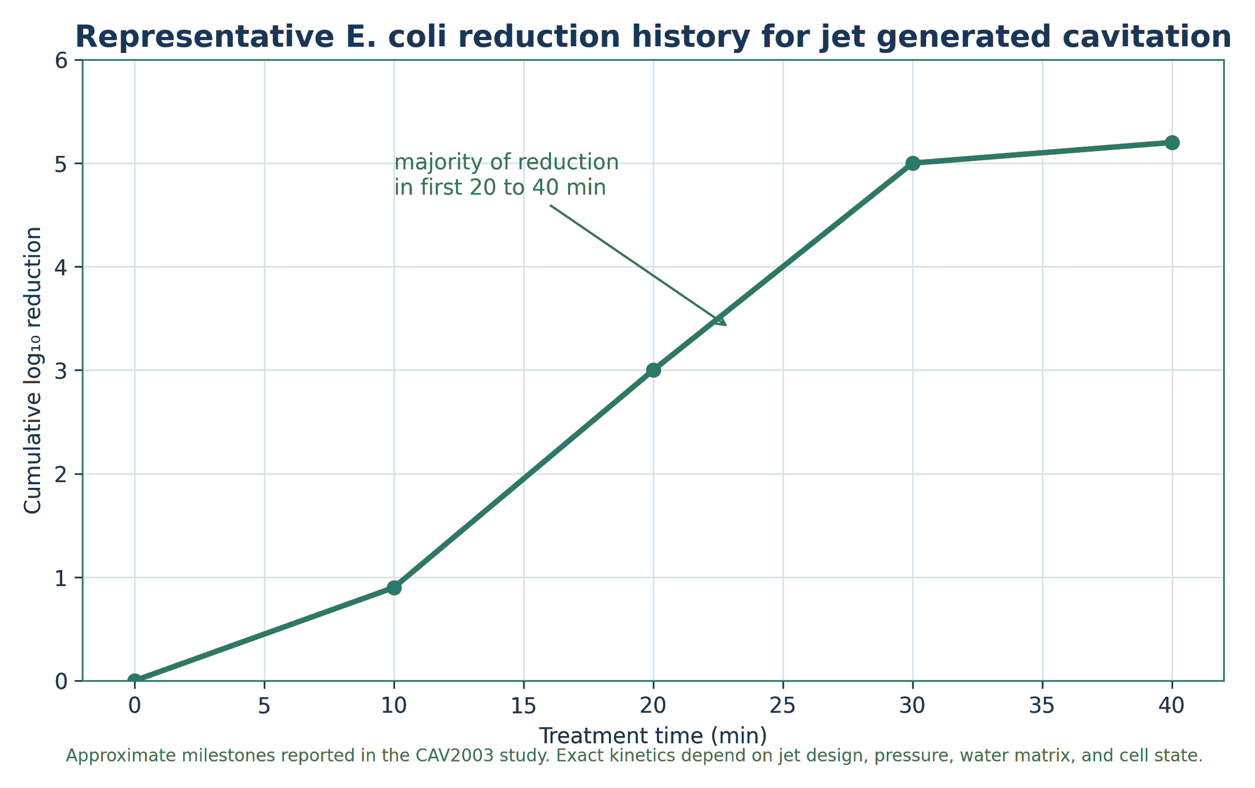
Figure 6.2. Representative E. coli reduction history for jet generated cavitation [17].
6.3 Bacteria, Viruses, Algae, and Zooplankton
Jyoti and Pandit described HC as an energy efficient physical disinfection method relative to several nonchemical alternatives and showed that combining cavitation with hydrogen peroxide, ozone, or other treatments could increase inactivation rate [40,41,64]. Arrojo, Benito, and Martínez Tarifa compared chamber geometries and concluded that, under their conditions, hydrodynamic disinfection was strongly associated with mechanical disruption, particularly in configurations that promoted large bubbles and extended pressure oscillations [42]. Van der Walt et al. evaluated HC, ultraviolet radiation, and ultrasound individually and in combination. In filtered water, the combined treatment produced average reductions above 90% for standard plate counts, total coliforms, fecal coliforms, and bacteriophages, whereas average Clostridium reduction was about 79%. These results are study specific but demonstrate the value of complementary mechanisms and endpoint specific verification [73].
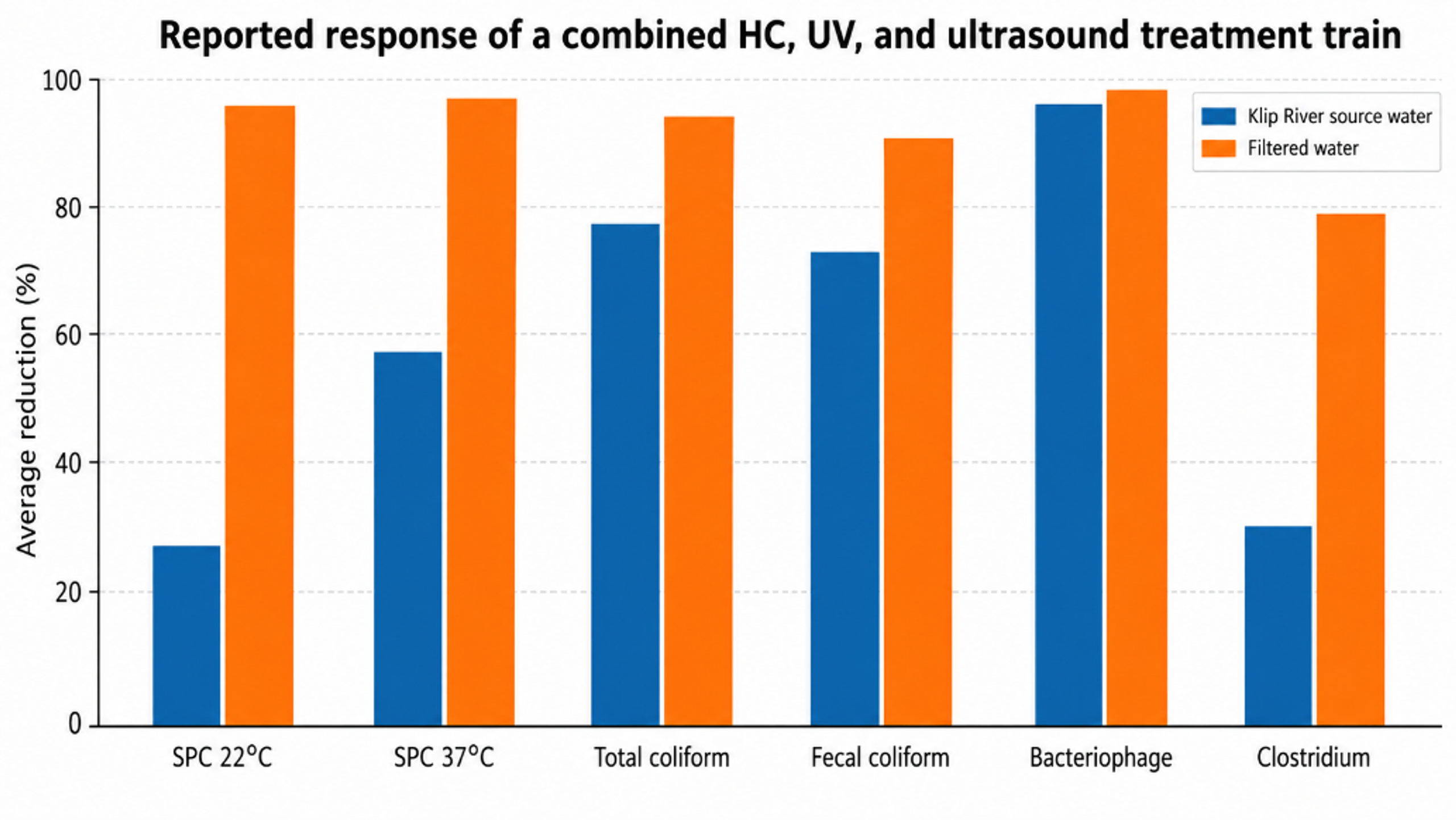
Figure 6.3. Average microbial reductions reported for a combined hydrodynamic cavitation, ultraviolet, and ultrasound treatment system [73].
Sawant et al. studied zooplankton in seawater and developed a framework relating turbulent shear and cavity dynamics to organism damage [39]. The relatively large size and fragile structures of many zooplankton make them responsive to mechanical events, but complete ballast treatment also requires control of smaller microorganisms and regrowth. Dular et al. later demonstrated that different cavitation regimes should be selected for different biological targets. In their study, supercavitation was effective for Legionella inactivation, whereas toxic cyanobacteria, green microalgae, and rotavirus exhibited different sensitivities [4].
Reductions in culture count, RNA signal, membrane integrity, and metabolic activity do not represent identical biological endpoints. A robust protocol should distinguish immediate injury, loss of culturability, loss of infectivity, delayed recovery, and regrowth. Controls should account for pump shear, temperature, sampling, and holding time. For reuse and ballast applications, treated water should be evaluated through the relevant storage period.
Table 6.1. Representative biological targets and dominant HC considerations.
| Target | Likely dominant response | Recommended verification |
|---|---|---|
| Vegetative bacteria | Mechanical membrane damage plus oxidative stress | Culture, membrane integrity, delayed regrowth, residual disinfectant |
| Spores or resistant bacteria | Higher mechanical and chemical resistance | Validated multi barrier treatment and long holding study |
| Viruses | Capsid and genome damage, often requiring repeated exposure or oxidant | Infectivity assay, not nucleic acid signal alone |
| Cyanobacteria and microalgae | Cell rupture, buoyancy change, pigment release, toxin release risk | Cell count, viability, dissolved toxin, downstream separation |
| Zooplankton and larvae | Shear, pressure oscillation, microjet and shock damage | Viable organism count by size class |
| Mixed natural water | Matrix dependent combination of effects | Standardized challenge organisms, real water trials, regrowth and ecotoxicity |
6.4 Rotational Cavitation and the Contribution of Bulk Heating
Sun et al. investigated an advanced rotational HC reactor containing a 260 mm rotor with cone shaped dimples and stationary front and rear covers with different dimple counts. A 15 kW motor operated the rotor at 2700 to 3600 rpm, while a separate pump controlled flow and inlet pressure. Repeated interaction between moving and stationary cavities produced strong local cavitation and substantial conversion of shaft power to heat [62].
The maximum reported heat generation rate was 48.15 MJ h⁻¹ and the maximum thermal efficiency was 82.18%. In the disinfection experiments, the authors identified bulk thermal exposure as the dominant factor. At approximately equal final temperatures near 65 °C after 14 minutes, rotational HC achieved complete plate count inactivation and an 8.3 log reduction, whereas conventional heating produced 24.14% inactivation and a 0.12 log reduction. The comparison indicates that thermal history and cavitational damage acted together in this reactor [62].
This result is reactor specific and should not be generalized to all HC devices. In a low pressure Venturi or jet reactor with active cooling, bulk temperature may remain too low to contribute materially. Conversely, an uncooled high power rotor can function as both a cavitation reactor and a rapid heater. Disinfection studies should therefore include a matched thermal control, a complete temperature time history, power measurement, and direct assessment of the nonthermal contribution.
6.5 Viability, Sublethal Injury, and Regrowth
Mezule et al. used a small rotor device to treat E. coli in a 2 L system. Three minutes of exposure at a reported energy density of 490 W L⁻¹ stopped division in approximately 75% of the cells, while most cells retained measurable respiratory activity. The authors interpreted this condition as an active but nonculturable state and recommended investigation of possible resuscitation [61]. This distinction is important for reuse and drinking water applications.
A reliable disinfection study should combine culture or plaque assays with at least one independent measure of cellular or viral integrity or metabolic state. Suitable methods include membrane staining, respiration assays, ATP measurements, flow cytometry, quantitative polymerase chain reaction with viability treatment, and host infectivity assays for viruses. Reduction of a molecular signal alone does not establish loss of infectivity, while loss of culturability alone may fail to detect injured organisms that subsequently recover.
Independent virus studies provide stronger evidence when infectivity is measured directly. Kosel et al. achieved more than 4 log reduction of MS2 bacteriophage infectivity in 3 mL and 1 L Venturi reactors, demonstrating that HC can inactivate a virus surrogate when the endpoint is a plaque assay [68]. The result also demonstrates the need to report reactor scale, initial titer, pass number, and infectivity assay together.
6.6 Cyanobacteria, Microalgae, and Cyanotoxin Control
Cyanobacterial treatment has two concurrent objectives: control of cells and control of toxins. Mechanical rupture may reduce viable biomass while releasing intracellular microcystin. A suitable treatment process must therefore either avoid uncontrolled lysis or provide sufficient oxidation after lysis. Chlorophyll, turbidity, cell count, photosynthetic activity, extracellular toxin, intracellular toxin, and post treatment regrowth should be evaluated together [4,63].
The ERDC study compared four nozzle configurations in large treatment tanks. Three conventional jet nozzles produced limited radical signatures and inconsistent biological effects. A submerged nano micro bubble nozzle supplied with compressed air produced the clearest hydroxyl and superoxide signatures and the strongest combined decreases in turbidity, chlorophyll a, and microcystin. The nozzle operated at approximately 22.3 L min⁻¹, with water pressure near 25.3 psi and air pressure near 1.2 psi [63].
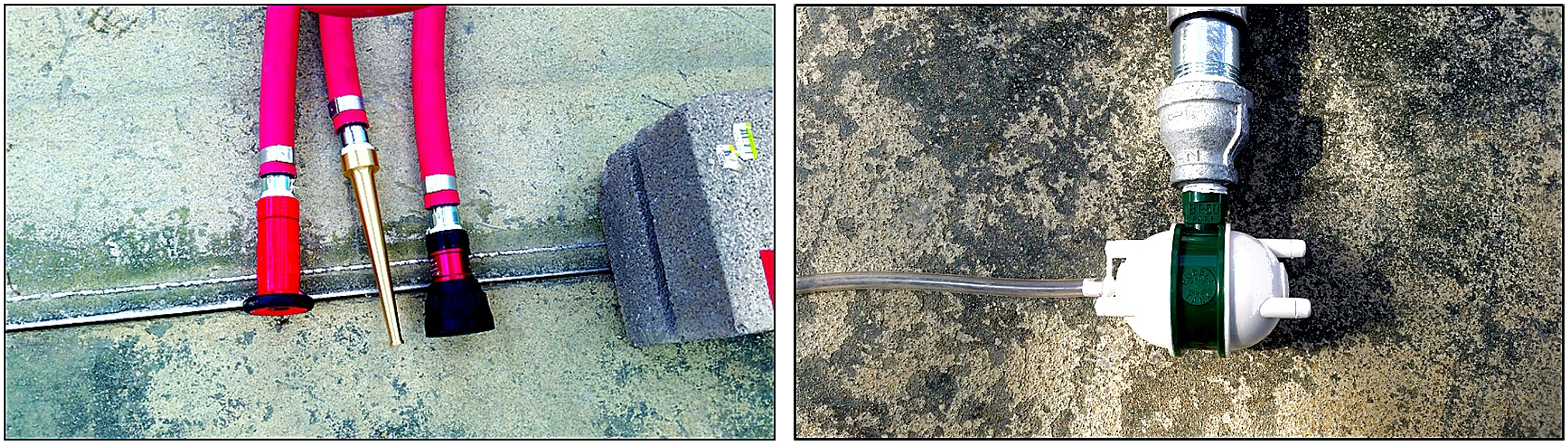
Figure 6.4. Conventional and submerged gas assisted nozzles evaluated in the U.S. Army ERDC cyanobacteria study [63].
The reported two hour treatment with the nano micro bubble nozzle reduced chlorophyll a by approximately 95% and microcystin by approximately 47.5%. The difference between these endpoints confirms that cell or pigment removal cannot be used as a surrogate for complete toxin destruction. Water in a separate 15 L demonstration also became visibly clearer, but visual clarity is not a substitute for toxin analysis [63].
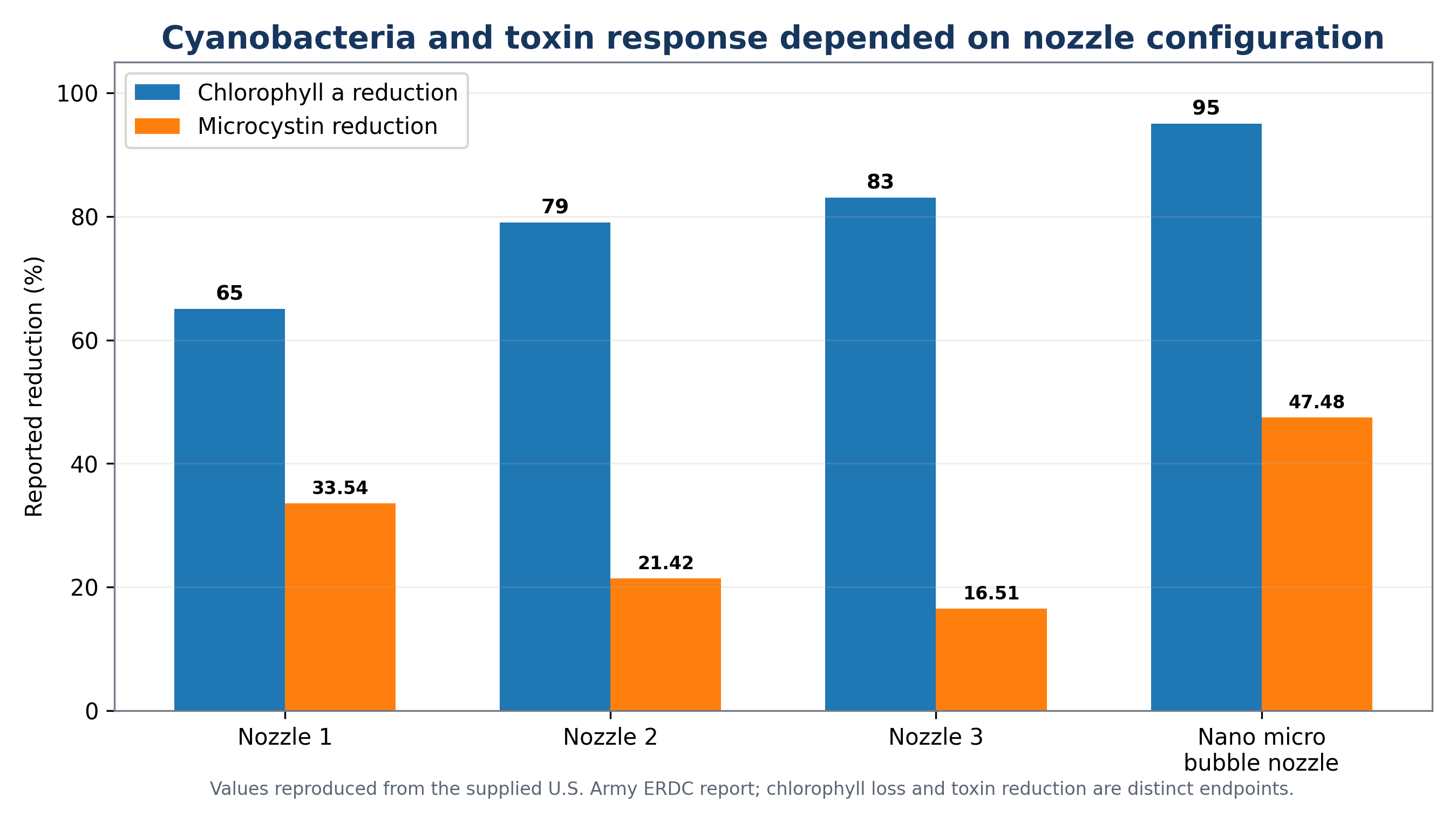
Figure 6.5. Reported chlorophyll and microcystin response for the ERDC nozzle configurations [63].
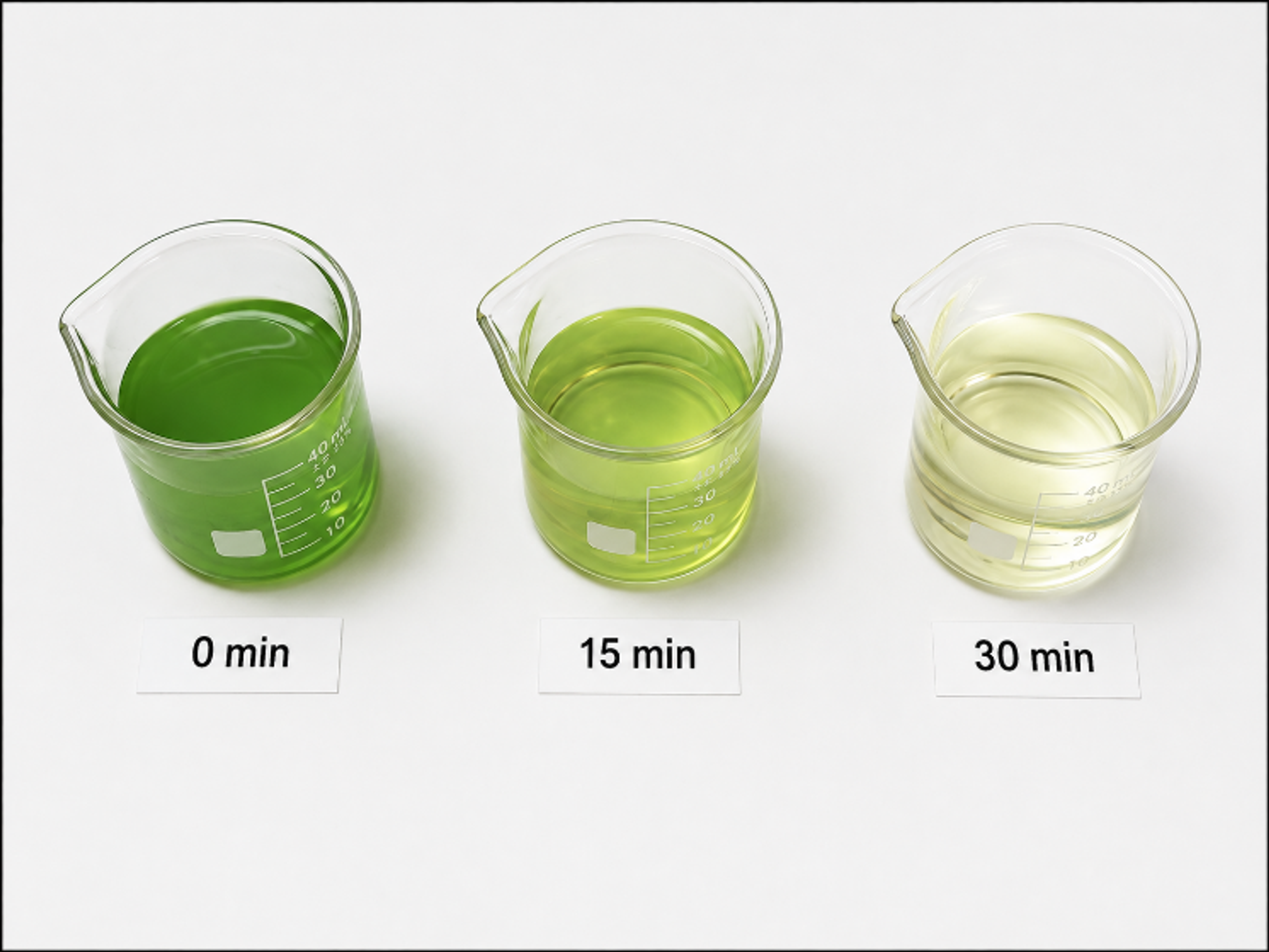
Figure 6.6. Visual change during treatment of a Microcystis aeruginosa suspension [63].
Results across cyanobacteria studies remain strongly dependent on species and reactor configuration. Gas vesicles, cell wall composition, colony structure, and extracellular polymeric material affect susceptibility. Under some conditions, HC can inhibit cyanobacterial growth without visible lysis, whereas more aggressive cavitation can rupture cells. Field deployment in lakes or reservoirs must therefore consider ecological selectivity, resuspension, oxygen demand, toxin release, and the fraction of the water body that is actually treated.
7 Oxidation of Organic Components
7.1 Reaction Domain Selection
Organic oxidation encompasses several distinct objectives: transformation of a parent compound, ring opening, dehalogenation, reduction of COD, reduction of TOC, detoxification, and complete mineralization to carbon dioxide, water, and inorganic ions. HC can accomplish some or all of these objectives, but required exposure and chemistry differ among targets. Volatile organic compounds can enter the cavity and undergo pyrolysis or radical attack. Hydrophobic nonvolatile compounds preferentially occupy the interface. Hydrophilic nonvolatile compounds remain in the bulk liquid, where radical delivery is limited by short radical lifetime and matrix scavenging [2,4,18,21].
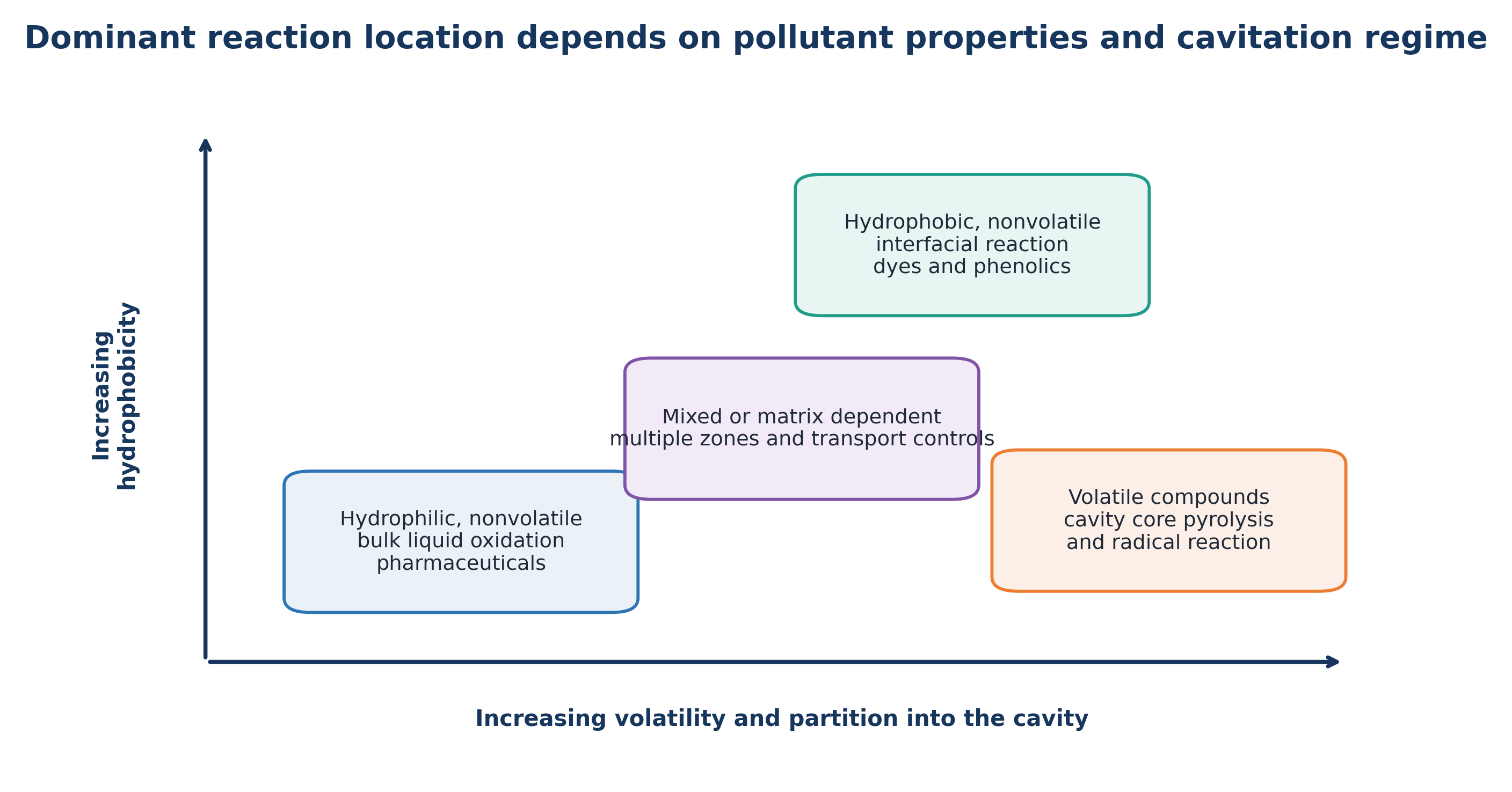
Figure 7.1. Dominant organic contaminant reaction domain as a function of volatility, hydrophobicity, and partitioning [11].
Equation (7.1) represents hydrogen abstraction by a hydroxyl radical (•OH), a fundamental elementary step in free radical chemistry, advanced oxidation processes, and cavitation induced degradation.
Equation (7.2) represents a reaction sequence rather than a single elementary step. The intermediate pathway depends on molecular structure and water matrix. Chlorinated compounds can form chloride and low molecular weight acids, nitrogen containing pharmaceuticals can form nitrogenous intermediates, and aromatic compounds can produce hydroxylated and ring opened products. Analytical screening is therefore necessary when treated water will be reused or discharged to a sensitive receiving environment.
7.2 Phenols, Dyes, Pesticides, and Industrial Organics
Phenols and dyes are frequently used as model compounds because they are analytically convenient and span different reaction domains. The p-nitrophenol study demonstrates the pressure optimum discussed previously [16]. Experiments with Methyl Orange and 2,4-D using cavitating jets showed that maximum removal rate and maximum energy efficiency can occur at different jet pressures [17]. The advanced Fenton study on 2,4-D showed that HC alone generated insufficient radicals for deep mineralization, whereas combination with hydrogen peroxide and zero valent iron reduced residual TOC to about 30% after 20 minutes in the reported system [22].
For nonvolatile compounds, Sayyaadi introduced an enhanced cavitation oxidation process in which H₂O₂ was injected upstream of a Venturi. Across the tested range, peroxide dose affected 2-chlorophenol degradation more strongly than cavitation number. Energy efficient operation favored mild cavitation, an adequate peroxide dose, and short injection duration, whereas maximum decomposition rate favored more intense cavitation [21]. The operating point that minimizes treatment time is therefore not necessarily the point that minimizes cost or carbon intensity.
7.3 Pharmaceuticals and Personal Care Products
Pharmaceuticals present a difficult treatment target because they occur at low concentrations, can remain biologically active, and coexist with natural organic matter and inorganic radical scavengers. In the reviewed pharmaceutical study, six compounds were treated with HC and H₂O₂. In deionized water, naproxen, carbamazepine, and diclofenac showed high removal under optimized conditions, whereas clofibric acid, ibuprofen, and ketoprofen showed less consistent response. In real effluent, removal decreased unless exposure and oxidant dose were increased [4,44].
A review by Liu et al. concluded that pharmaceutical HC research includes standalone HC and combinations with H₂O₂, persulfate, peroxymonosulfate, percarbonate, Fenton reagents, catalysts, ozone, and photocatalysis [45]. Recent scale up work combined HC with nonthermal electrical discharge plasma. A pilot reactor operating at 600 L h⁻¹ and a semi industrial reactor at 3200 L h⁻¹ achieved near quantitative degradation of ibuprofen and diclofenac solutions after 13 passes, with comparable energy efficiency and no detectable final byproducts under the reported conditions [46]. A 2026 ofloxacin study reported 74.93% degradation by optimized standalone HC at pH 3 and 4 bar, increasing to approximately 95% with advanced Fenton coupling [47]. Recent studies have also extended HC and hybrid HC treatment to cefixime, antibiotics in aquaculture seawater, triclosan, and rhodamine B, reinforcing the need to optimize aeration, ozone or peroxide dose, and hydraulic severity for each compound and matrix [48-51]. These studies indicate continued progress, but real wastewater performance, chronic toxicity, maintenance, and life cycle comparisons remain necessary before broad implementation.
Table 7.1. Selected organic contaminant studies and design lessons.
| Target or matrix | Treatment | Representative outcome | Lesson |
|---|---|---|---|
| p Nitrophenol [16] | Venturi HC | Optimum near 0.4-0.45 MPa | Hydraulic severity has a nonmonotonic optimum |
| 2,4-D [17,22] | Cavitating jet; HC with advanced Fenton | Order of magnitude jet reduction; deep TOC reduction with hybrid process | Mechanical and chemical routes can be combined |
| 2-Chlorophenol [21] | Venturi HC plus injected H₂O₂ | Dose dominated response; excess oxidant reduced yield | Optimize oxidant and cavitation jointly |
| Wood finishing wastewater [20] | Rotor stator HC plus H₂O₂ | High COD reduction at optimum speed and dose | Real wastewater can respond when volatile and interfacial compounds are present |
| Six pharmaceuticals [4,44] | HC plus H₂O₂ | Compound- and matrix specific removal | Clean water results cannot be transferred directly to effluent |
| Ibuprofen and diclofenac [46] | HC plus nonthermal plasma | Pilot to 3200 L h⁻¹, 13 passes, near complete degradation | Preserving residence time and energy efficiency can enable scale up |
| Ofloxacin [47] | HC, H₂O₂, hypochlorite, Fenton, advanced Fenton | 74.93% HC alone; up to 95.18% hybrid | Hybrid chemistry can substantially increase antibiotic removal |
7.4 Hybrid Process Selection
Hybrid treatment is justified when the target resides mainly in the bulk liquid, when the real water matrix consumes radicals, when standalone HC produces only partial transformation, or when residual disinfection is required. Hydrogen peroxide is simple to dose but has a narrow optimum and requires residual measurement. Ozone benefits from HC enhanced gas liquid transfer and decomposition but requires off gas management and bromate control. Fenton chemistry can be highly effective at acidic pH but introduces iron management and sludge production. Persulfate and peroxymonosulfate can generate sulfate radicals but require activation and byproduct evaluation. Plasma and photocatalysis can add reactive species without a bulk chemical inventory, although electrical and reactor complexity increase [21,22,25,45-47].
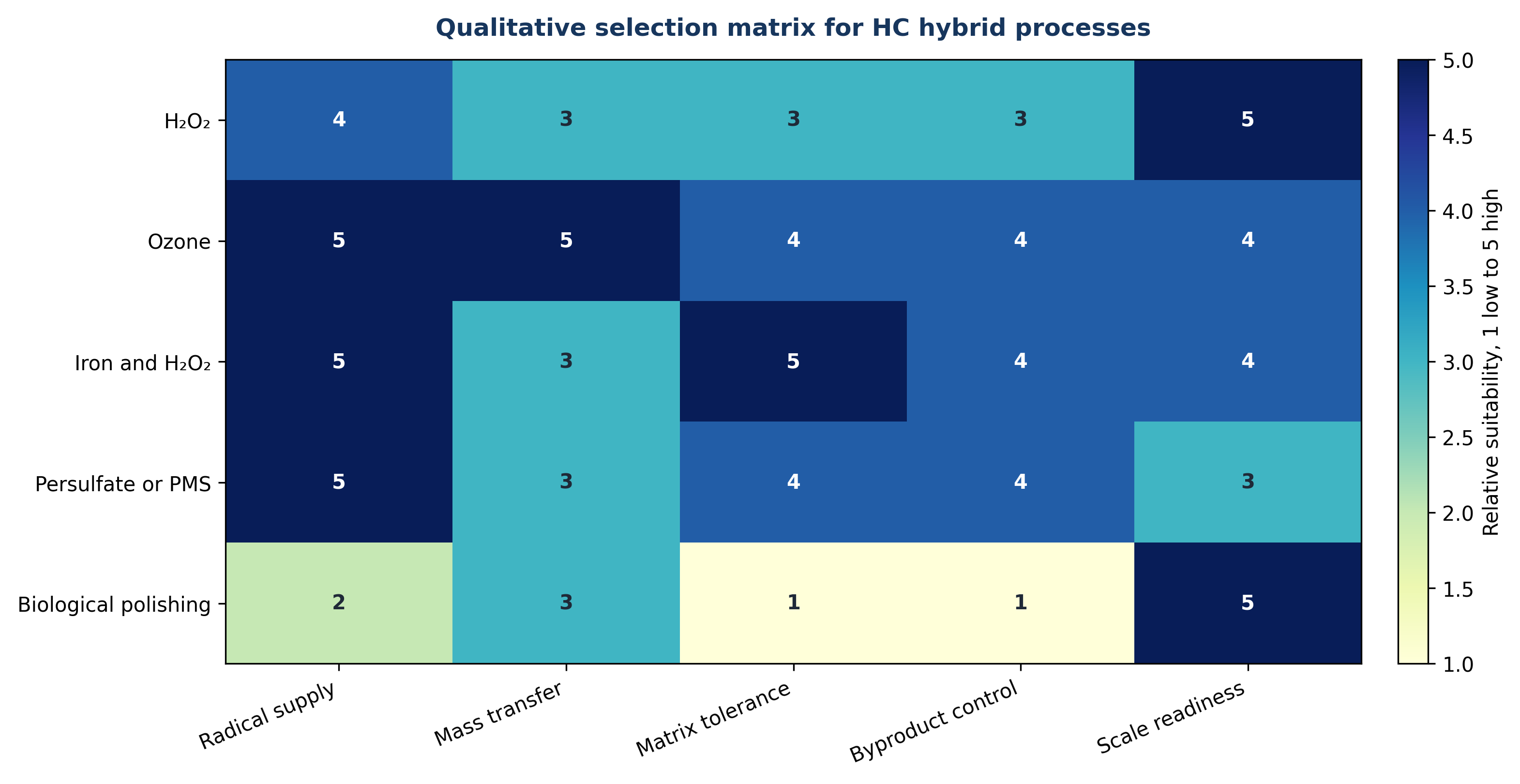
Figure 7.2. Qualitative selection matrix for hydrodynamic cavitation hybrid processes [11].
7.5 Industrial, Mining, and High Solids Effluent Treatment
Industrial and mining effluents often contain multiple contaminant classes that require different treatment mechanisms. Suspended mineral particles and oil can be separated physically, dissolved metals can be oxidized or precipitated, ammonia and cyanide require targeted chemistry, and refractory organic compounds may require radical oxidation. HC is most effective when it intensifies one of these unit operations rather than when it is treated as a universal separator.
The National Research Council presentation reviewed in the source material proposed integrated process trains for drill water, mine water, flotation, oil dispersion, electrocoagulation, and ozone assisted treatment [67]. These examples are process concepts rather than a uniform performance dataset. They nevertheless support a consistent design principle: HC should be positioned after gross solids removal and before the reaction or separation step that benefits from rapid micromixing, gas transfer, surface renewal, or nucleation.
Hydrodynamic cavitation does not independently remove dissolved metal ions. It can accelerate oxidation of ferrous iron, improve reagent dispersion, increase precipitation nuclei, or support electrocoagulation, after which solids must be separated. In petroleum wastewater, aggressive mixing can either assist flotation through gas dispersion or create a stable emulsion that is more difficult to separate. The treatment objective and downstream separation method should therefore be defined before cavitation severity is selected.
High suspended solids and abrasive grit affect both hydraulic performance and equipment life. Particles can increase the population of cavitation nuclei, but they can also block small openings and erode pumps, valves, and rotor surfaces. Pilot testing should therefore use the actual particle size distribution, mineral hardness, oil content, temperature, and chemical composition. Clean water hydraulic tests are necessary for commissioning but are insufficient for process prediction.
Table 7.2. Industrial wastewater mechanisms and downstream requirements.
| Dominant contaminant | Potential role of HC | Required downstream step | Critical evidence |
|---|---|---|---|
| Refractory dissolved organics | Radical formation, oxidant activation, improved mass transfer | Biological treatment, adsorption, membrane, or final oxidation | TOC, transformation products, toxicity, EEO |
| Dissolved metals | Oxidation state control, reagent dispersion, precipitation nucleation | Clarification, flotation, filtration, or sludge handling | Dissolved and total metals, pH, solids settleability |
| il and grease | Gas dispersion, droplet breakup, interfacial renewal | Flotation, coalescer, skimming, or membrane | Droplet size, residual oil, emulsion stability |
| Mineral suspended solids | Agglomerate breakup or enhanced flotation contact | Hydrocyclone, clarifier, filter press | Wear rate, pressure loss, particle size, cake properties |
| Ammonia, cyanide, or sulfide | Targeted oxidation with selected reagent | Gas control, biological polishing, residual removal | Stoichiometry, off gas, byproducts, acute toxicity |
| Mixed high COD wastewater | Pretreatment to improve biodegradability | Aerobic or anaerobic biological process | BOD to COD ratio, respirometry, methane potential, inhibition |
7.6 Recent Developments
Recent research has shifted from demonstrating cavitation effects toward defining reactor function, upper treatment limits, and scale. In waste activated sludge, Abdelrahman et al. found that 0.83 MPa produced a larger methane benefit than 1.72 MPa, while Son et al. reported biogas improvement ranging from 14.4% to 96.5% across advanced rotational conditions and warned that excessive treatment could reduce yield [30,31]. These results reinforce the need to optimize HC against downstream biological response rather than maximum SCOD alone.
Pharmaceutical research now includes standalone HC and combinations with peroxide, Fenton chemistry, persulfate, peroxymonosulfate, ozone, catalysts, photocatalysis, and plasma [45]. Verdini et al. extended a cavitation plasma process from approximately 600 L h⁻¹ to 3200 L h⁻¹ and reported near complete degradation of ibuprofen and diclofenac solutions after repeated passes [46]. Gandhi and Gogate reported 74.93% ofloxacin degradation by optimized HC alone and approximately 95% with advanced Fenton coupling [47].
These developments indicate progress, but the evidence hierarchy remains important. Many high removal values are obtained in prepared solutions at acidic pH and low contaminant concentration. Real effluent contains carbonate, chloride, dissolved organic matter, surfactants, solids, and mixed pollutants that consume radicals and modify cavitation. Scale up claims should therefore include results for the actual matrix, energy per order, chemical demand, transformation product screening, toxicity, and continuous operating data.
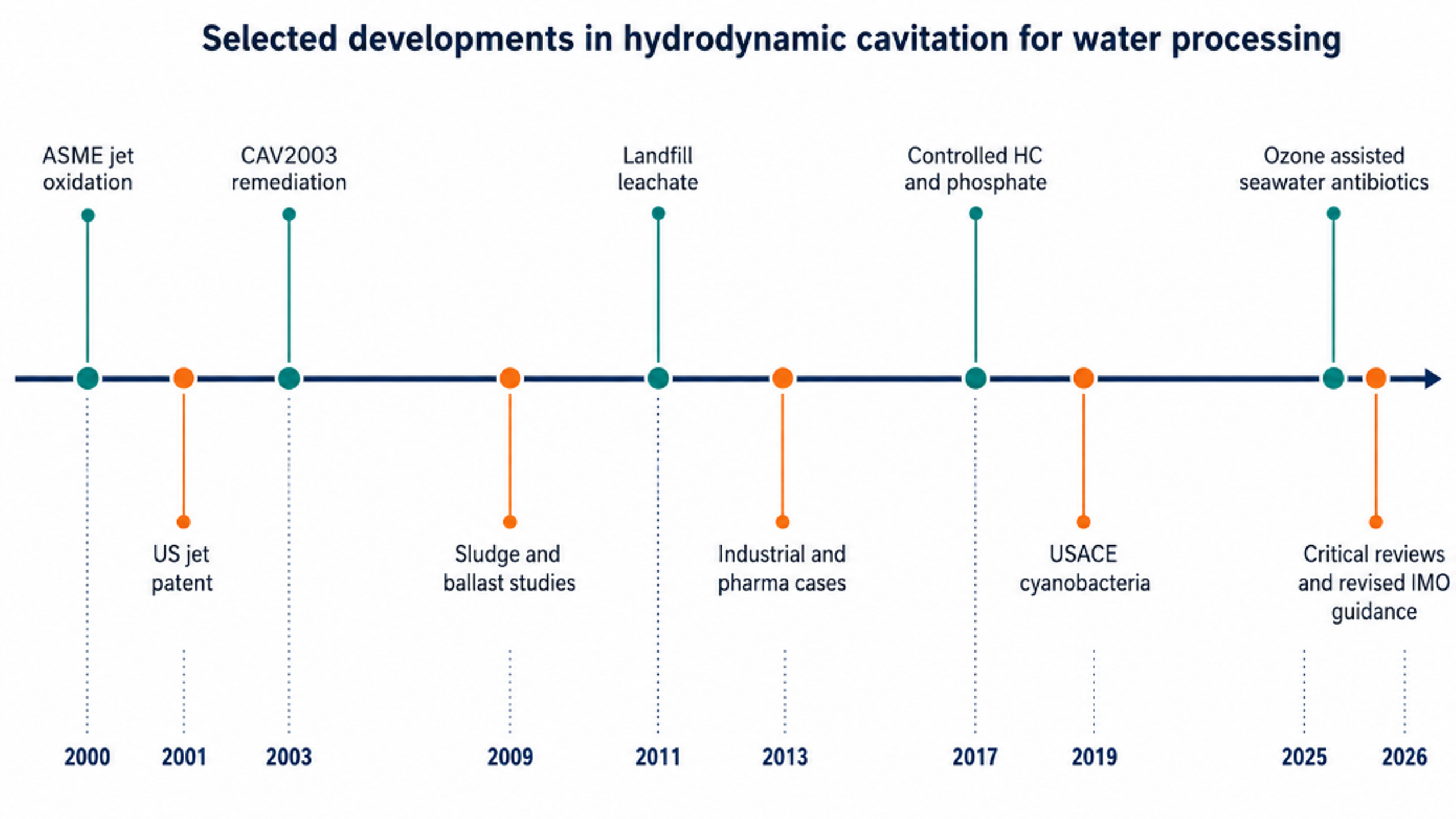
Figure 7.3. Selected developments in hydrodynamic cavitation for water processing through 2026 [11].
8 Process Design, Scale Up, and Energy
8.1 The Operating Window
A common design error is to assume that a larger pressure drop, higher rotor speed, or lower cavitation number must monotonically improve treatment. Useful response increases after inception, reaches an operating region in which cavity population and collapse are productive, and can then decline when vapor clouds shield collapse, flow becomes choked, or energy is dissipated without sufficient chemical or biological effect. Temperature can show a similar nonmonotonic influence because increased vapor pressure promotes cavity formation while increasing vapor cushioning during collapse [1-5,16,21,30,31].
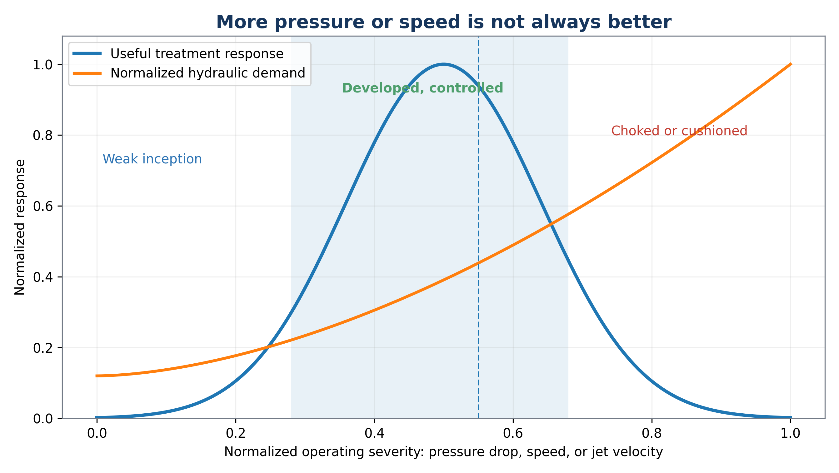
Figure 8.1. Conceptual operating window for hydrodynamic cavitation [11].
8.2 Similarity and Scale Up
Geometric similarity and a matched cavitation number do not guarantee identical treatment performance. Scale changes Reynolds number, turbulence structure, nuclei population, residence time distribution, pump efficiency, gas content, heat rejection, cavity cloud interactions, and the ratio of wall area to volume. Scale up should therefore preserve the process function, defined by the distribution of productive collapse events and the exposure of the target population or molecules.
The Reynolds number, Re, characterizes the ratio of inertial to viscous forces. The Weber number, We, characterizes the ratio of inertial to surface tension forces. A Damköhler type number, Da, compares reaction time with hydraulic exposure time. These indices supplement the cavitation number. For rotating equipment, tip speed, gap ratio, event frequency, torque, and specific power should also be considered. For jets, nozzle diameter, chamber pressure, standoff distance, entrainment, and jet interaction are important.
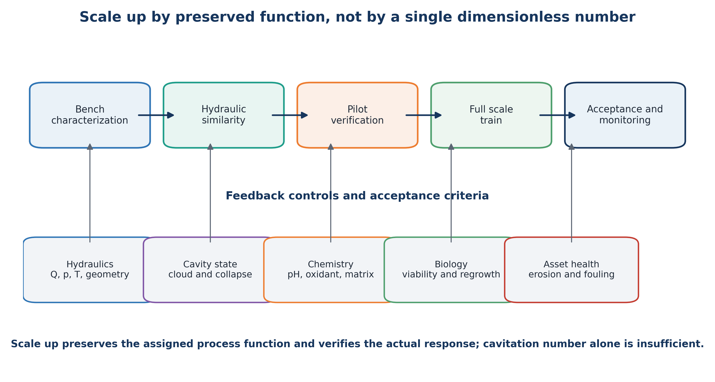
Figure 8.2. Scale up by preserving process function and verifying each development stage [11].
8.3 Energy and Economic Accounting
Energy accounting should include pumps, motors, variable frequency drives, cooling, gas compression, ozone generation, electrolysis, ultraviolet sources, plasma power, mixing, and downstream separation. Chemical production and neutralization should be included in operating cost and, when possible, in life cycle assessment. The appropriate comparison is between complete treatment trains that meet the same endpoint rather than between a cavitation pump and a single competing device [53,54].
For sludge treatment, recovered methane and reduced biosolids disposal can offset pretreatment energy. For industrial effluent, improved biological treatability can reduce aeration demand and residence time. In ballast water treatment, compactness and reduced chemical inventory can provide operational value. For micropollutants, treatment cost should be normalized to treated water volume and required removal, while recognizing that EEO does not represent toxicity or mineralization.
Table 8.1. Bench to full scale HC design checklist.
| Design stage | Required evidence before proceeding |
|---|---|
| Bench characterization | Real water matrix, target endpoint, pH and temperature range, nuclei and solids behavior, oxidant demand, byproduct screen |
| Hydraulic development | Pressure map, flow curve, cavitation regime, heat balance, erosion location, pump efficiency, bypass and control strategy |
| Pilot verification | Continuous operation, residence time distribution, energy per treated volume, maintenance intervals, analytical reproducibility, toxicity and regrowth |
| Full scale design | Redundancy, isolation, clean in place or inspection access, replaceable wear parts, hydraulic turndown, and maintenance access |
| Performance verification | Performance at minimum and maximum flow, worst case water quality, defined holding time, endpoint and uncertainty, residuals, noise, and vibration |
| Lifecycle operation | Confirm the pressure power relation, inspect wear, update chemistry, retain treatment records, and reassess when feed composition changes |
8.4 Quantitative Performance and Energy Normalization
Treatment performance should first be reported using a clearly defined analytical endpoint. For a concentration based response, percentage removal is given by:
where ηR is removal efficiency, C₀ is the initial concentration, and Ct is the concentration after treatment time t. When a pseudo first order model is justified over the measured interval, the concentration response is expressed as:
where kobs is the observed rate constant. A fitted rate constant is meaningful only when analytical method, temperature, mixing, and initial concentration are sufficiently comparable.
The hydraulic power transferred across a static cavitation device can be approximated by:
The associated electrical demand is:
where Δp is the measured pressure difference, Q is volumetric flow rate, ηp is pump efficiency, and ηm is motor and drive efficiency. For a rotating device, measured electrical or shaft power should be used directly and reported separately from auxiliary pump demand.
Specific energy input to the treated volume is:
For contaminant degradation, electrical energy per order is:
EEO is meaningful only when the same power boundary and treatment volume are used. It becomes unstable for small concentration changes and does not account for chemical consumption, cooling, or downstream process value.
A concentration based cavitational yield can be expressed as:
The nominal number of recycle turnovers and the mean hydraulic residence time are:
Nominal turnover does not imply equal exposure of every fluid element because short circuiting, dead zones, and bypass flow generate a residence time distribution. Tracer testing or computational fluid dynamics should be used when exposure uniformity is important.
Bulk temperature rise is described by the overall energy balance:
where m is liquid mass, cp is heat capacity, and Ploss is the thermal power rejected to the surroundings and cooling system. This balance separates useful thermal duty from uncontrolled heat accumulation.
For a hybrid process, a simple kinetic synergy index can be defined as:
where kHC+X is the observed rate constant for the combined process and kHC and kX are the corresponding standalone values. A value of S greater than one suggests kinetic synergy, but the conclusion should also be tested using mineralization, toxicity, and total energy and chemical cost.
A plant level net energy balance can be written as:
where recoverable biogas energy and avoided aeration or disposal energy are credited against cavitation, chemical, and cooling demands. Monetary value should be calculated separately because electricity, heat, disposal, and chemical consumption are not equivalent energy terms.
Hydraulic similarity is commonly described using the cavitation number and, for rotating equipment, rotor tip speed and power number:
Here p₂ is a downstream reference pressure, pv is vapor pressure, ρ is liquid density, vc is characteristic velocity, Dr is rotor diameter, N is rotational speed, and Pshaft is shaft power. These quantities support comparison among systems, but none uniquely determines bubble cloud structure or treatment performance. Scale up must preserve process function and verify the resulting treatment response.
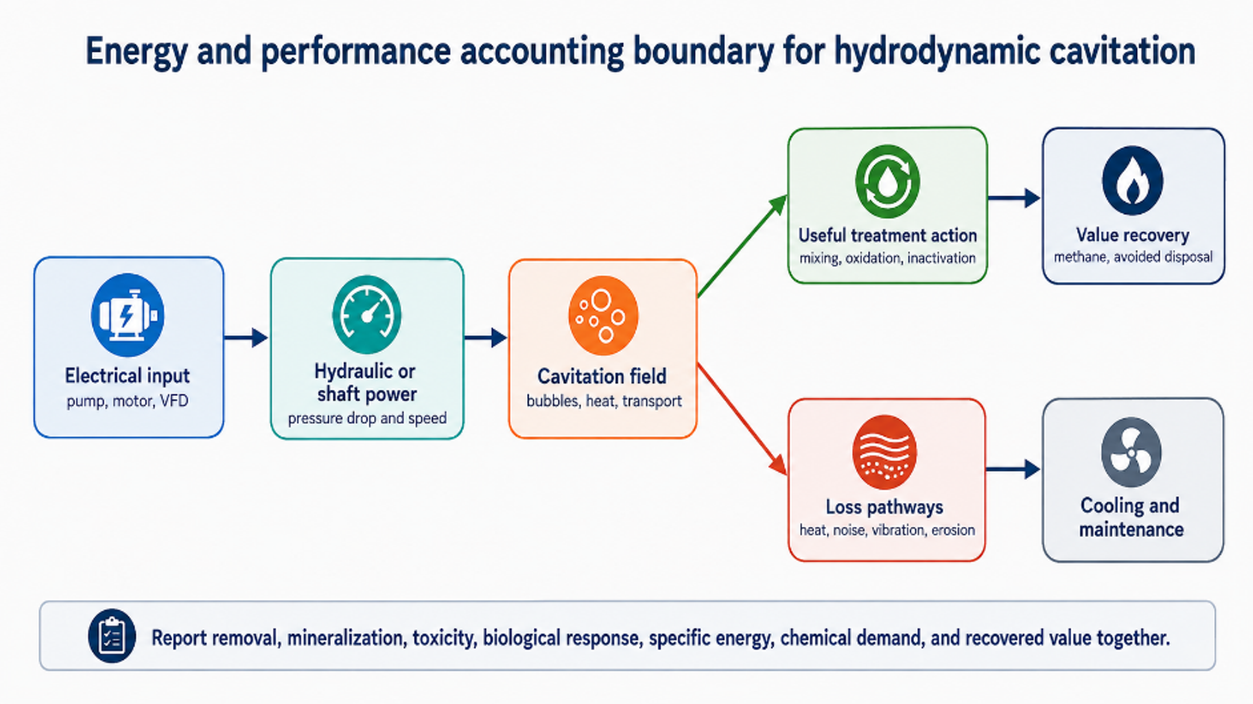
Figure 8.3. Energy and performance accounting boundary for hydrodynamic cavitation [11].
Table 8.2. Minimum normalized reporting set for HC studies and pilot trials.
| Category | Minimum reported variables | Reason |
|---|---|---|
| Hydraulics | Flow, upstream and downstream pressure, temperature, device geometry, backpressure, loop volume, pass count | Defines the actual pressure and exposure history |
| Power and energy | Electrical power by component, shaft or hydraulic power, cooling duty, specific energy, EEO or yield | Prevents incomplete energy comparisons |
| Water matrix | pH, conductivity, alkalinity, chloride, DOC or TOC, solids, dissolved gas, initial concentration | Explains radical scavenging and cavitation changes |
| Treatment outcome | Parent compound, COD, TOC, biodegradability, toxicity, biological response, transformation products | Separates disappearance from useful treatment |
| Asset condition | Noise, vibration, erosion, fouling, pressure stability, maintenance interval | Links treatment to equipment life and operability |
| Uncertainty | Replicates, analytical precision, blank and thermal controls, mass balance closure | Establishes whether differences are significant |
8.5 Materials, Erosion, Solids Handling, and Control
Cavitation erosion occurs when collapse is repeated on or very near a solid surface. Water treatment reactors should therefore locate the most intense collapse within the liquid whenever possible and use replaceable sacrificial components where impact cannot be avoided. Candidate materials include stainless steels, duplex alloys, hard coatings, ceramics, and engineered polymers, but selection must account for corrosion, chloride concentration, temperature, abrasive solids, cyclic stress, weld quality, and cleaning chemicals. Material ranking obtained from clean water erosion tests may change in actual wastewater.
Fibers, rags, grit, precipitates, and scale are common causes of performance loss. Upstream screening or maceration, drain and flush connections, reversible flow, accessible nozzles, and differential pressure alarms should be incorporated during initial design. Rotating equipment additionally requires seal flushing, bearing monitoring, vibration limits, and torque protection. In oxidant systems, compatible seals and controlled injection location are required to prevent concentrated chemical attack.
A robust control system maintains the desired operating window rather than a fixed pump pressure alone. Manipulated variables may include motor speed, control valve position, downstream backpressure, recycle ratio, gas injection, oxidant dose, and cooling flow. Protective interlocks should respond to low flow, excessive temperature, pressure instability, vibration, seal failure, high residual oxidant, and loss of neutralization capacity.
Table 8.3. Common failure modes and engineering safeguards.
| Failure mode | Likely cause | Process consequence | Safeguard or diagnostic |
|---|---|---|---|
| Loss of cavitation response | Nozzle wear, blockage, gas change, backpressure drift | Lower oxidation, lysis, or inactivation | Pressure profile, acoustic or vibration signature, power and flow trend |
| Excessive vapor structure | Backpressure too low or temperature too high | Vapor shielding and weak collapse | Control downstream pressure and temperature |
| Rapid erosion | Collapse attached to wall, abrasive solids, unsuitable material | Metal loss, contamination, unplanned outage | Move collapse zone, replaceable insert, erosion inspection coupon |
| Plugging or ragging | Fibers, grit, precipitate, inadequate screening | Flow imbalance and pump overload | Macerator, screen, flush ports, differential pressure alarm |
| Biological deterioration after sludge treatment | Excessive exposure or inhibitory soluble products | Lower methane yield or unstable digestion | BMP testing, staged treated fraction, SCOD and ammonia monitoring |
| Oxidant inefficiency | Overdose, scavenging, poor injection, incorrect pH | Higher chemical cost and byproducts | Dose response testing, residual measurement, TOC and toxicity |
| Uncontrolled heating | High recirculation power and insufficient cooling | Confounded kinetics, vapor pressure change, safety risk | Heat balance, cooling loop, temperature interlock |
8.6 Pilot Protocol and Acceptance Criteria
Pilot development should proceed through defined evidence gates. The first stage maps clean water hydraulics and identifies stable ranges of pressure, flow, temperature, power, vibration, and backpressure. The second stage uses a safe tracer or model target to confirm residence time distribution and analytical repeatability. The third stage treats actual wastewater across the expected seasonal matrix range. The final stage operates continuously for sufficient duration to reveal fouling, erosion, sensor drift, maintenance demand, and downstream biological response.
Acceptance criteria must be linked to the plant objective. A polishing system may be evaluated using micropollutant removal, toxicity, and EEO. A sludge system requires net methane production, solids reduction, dewatering performance, and digester stability. A ballast water system requires certified biological performance and residual control. A precipitation system requires dissolved nutrient or metal removal together with acceptable solids separation. In every case, the guaranteed operating boundary should define feed quality, flow rate, temperature, and required auxiliary chemicals.
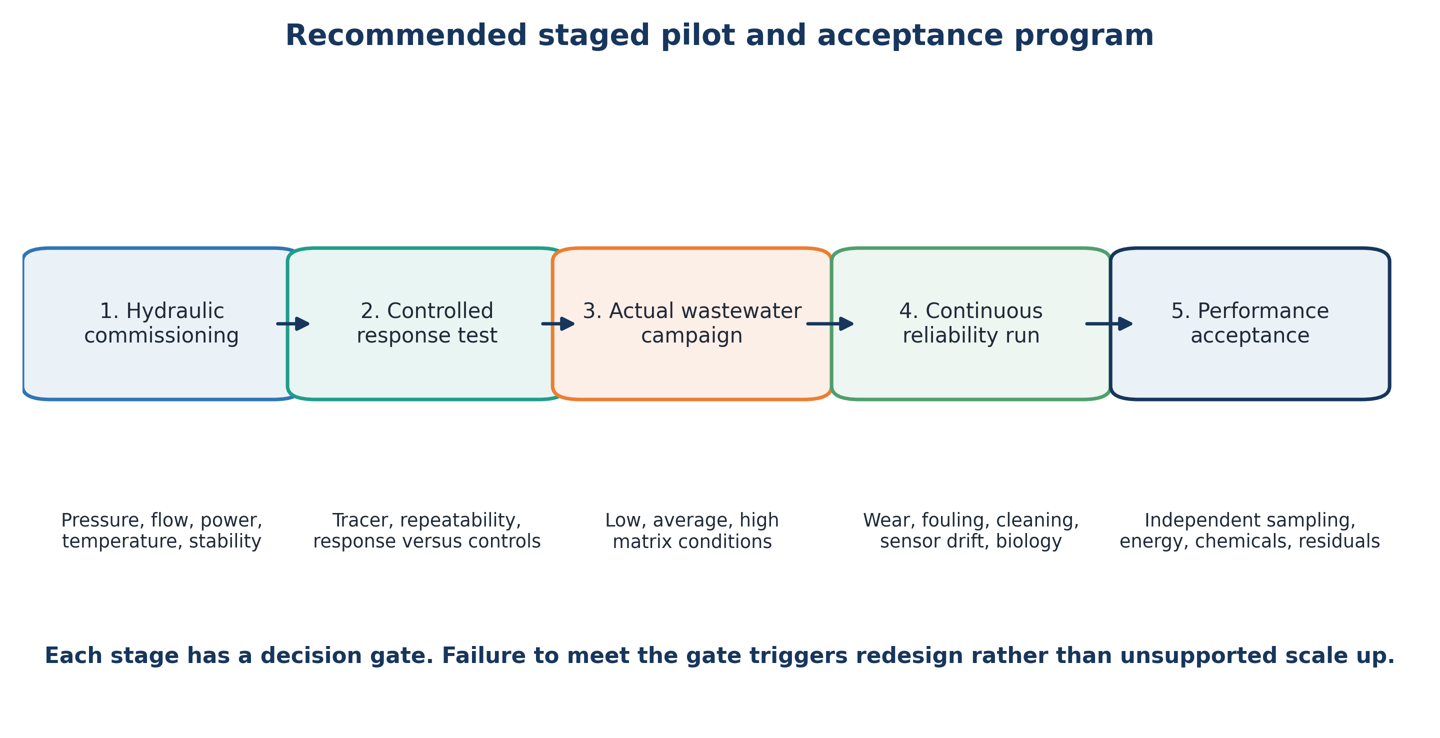
Figure 8.4. Recommended staged pilot and acceptance program [11].
Table 8.4. Recommended staged pilot program.
| Stage | Feed and duration | Primary measurements | Decision gate |
|---|---|---|---|
| 1. Hydraulic commissioning | Clean water over full pressure and flow map | Pressure profile, flow, power, temperature, vibration, cavitation stability | Safe and repeatable operating envelope |
| 2. Controlled response | Model solute, tracer, or standardized sludge test | Residence time distribution, removal kinetics, heat balance, replicate uncertainty | Evidence that response tracks controllable variables |
| 3. Actual wastewater campaign | Representative low, average, and high load matrices | Target removal, TOC or COD, toxicity, SCOD or BMP, chemical demand | Site specific optimum and treatment train position |
| 4. Continuous reliability run | Weeks to months at design duty | Wear, fouling, cleaning, sensor drift, availability, downstream process impact | Maintainable design and realistic operating cost |
| 5. Performance acceptance | Contract feed window and independent sampling | Guaranteed endpoints, energy, chemicals, residuals, asset condition | Documented compliance and handover criteria |
9 Conclusions
Hydrodynamic cavitation is a versatile process intensification method for water processing because it combines mechanical disruption, interfacial renewal, localized thermal effects, and radical chemistry in a flow through device. Its principal engineering advantage over localized acoustic systems is the ability to force the full process stream through a designed cavitation region using conventional hydraulic equipment.
Available evidence most consistently supports targeted applications. In wastewater treatment, HC can transform model compounds, pretreat refractory industrial effluent, activate oxidants, and improve contacting. In sludge processing, it can reduce particle size and release soluble substrates, thereby improving anaerobic digestion when treatment severity is optimized. In ballast water treatment and disinfection, HC can damage larger organisms directly and can reduce auxiliary chemical demand in hybrid systems. In organic oxidation, performance depends strongly on contaminant reaction domain and water matrix.
Treatment performance cannot be represented by a monotonic relation in which higher pressure, lower cavitation number, or higher rotor speed is always beneficial. Productive treatment generally occurs within an operating window between weak inception and vapor dominated or overtreated conditions. The optimum should be determined using the actual treatment endpoint together with an energy normalized metric.
Standalone HC often provides partial transformation rather than complete mineralization in concentrated or strongly scavenging matrices. Hybrid processes using hydrogen peroxide, ozone, Fenton reagents, persulfate, catalysts, or plasma can supply additional reactive species, but they also introduce chemical consumption, energy demand, byproducts, and operational requirements. Comparative evaluation should therefore consider complete treatment trains that achieve the same water quality objective.
Scale up should preserve treatment function rather than geometry or cavitation number alone. Continuous pilot verification should establish hydraulic distribution, energy demand, heat rejection, wear, chemistry, biological response, and maintenance requirements. When these factors are controlled, HC can be integrated as a practical pretreatment, side stream, disinfection, or polishing operation in municipal, industrial, marine, and water reuse systems.
Nomenclature
The following symbols are used in this article. Unless otherwise stated, quantities are expressed in SI units. Symbols retained from cited sources may follow the convention of the original source; the corresponding equation and surrounding definitions govern their interpretation.
| Symbol | Definition | SI unit or status |
|---|---|---|
| Ac | Flow area at the constriction or designated cavitating section | m² |
| C | Contaminant concentration | mol m⁻³, mg L⁻¹, or specified |
| C₀ | Initial contaminant concentration | same as C |
| Ct | Contaminant concentration at time t | same as C |
| CW | Disinfectant concentration in the Chick Watson model | mass volume⁻¹ |
| D | Characteristic hydraulic length or diameter | m |
| Da | Damköhler type reaction to hydraulic time ratio | dimensionless |
| DDCOD | Degree of sludge disintegration based on soluble COD | % |
| EEO | Electrical energy per order of contaminant reduction | kWh m⁻³ order⁻¹ |
| Ein | Energy input to the treatment system | J or kWh |
| Es | Specific electrical energy input | J m⁻³ or kWh m⁻³ |
| g | Gravitational acceleration | m s⁻² |
| hL | Specific irreversible hydraulic loss | J kg⁻¹ |
| k | Empirical inactivation or reaction constant | specified by model |
| kobs | Observed pseudo first order rate constant | s⁻¹ or min⁻¹ |
| kreaction | Characteristic reaction rate constant used in Da | s⁻¹ |
| LRV | Logarithmic reduction value | dimensionless |
| N₀ | Initial viable organism concentration | CFU or organisms per volume |
| Nt | Viable organism concentration after treatment time t | CFU or organisms per volume |
| Npass | Nominal number of treatment loop turnovers | dimensionless |
| p | Static pressure | Pa |
| p₂ | Recovered downstream reference pressure | Pa |
| pB | Pressure inside a cavity | Pa |
| p∞ | Far field liquid pressure | Pa |
| Pel | Estimated electrical pump power | W |
| Ph | Hydraulic power transferred to the liquid | W |
| pv | Liquid vapor pressure | Pa |
| Q | Volumetric flow rate | m³ s⁻¹ |
| R | Instantaneous bubble radius | m |
| Rmax | Maximum bubble radius before collapse | m |
| Re | Reynolds number | dimensionless |
| SCOD₀ | Initial soluble chemical oxygen demand | mg L⁻¹ |
| SCODt | Soluble chemical oxygen demand after treatment | mg L⁻¹ |
| SCODmax | Reference maximum soluble COD | mg L⁻¹ |
| t | Treatment time | s or min |
| tc | Idealized Rayleigh collapse time | s |
| V | Treated or recirculating liquid volume | m³ |
| v | Mean fluid velocity | m s⁻¹ |
| vc | Velocity in the constriction or designated cavitating region | m s⁻¹ |
| We | Weber number | dimensionless |
| Ycav | Cavitational yield | mass energy⁻¹ |
| YCH₄, c | Control methane yield | mL CH₄ g⁻¹ VS or specified |
| YCH₄, t | Methane yield after pretreatment | mL CH₄ g⁻¹ VS or specified |
| z | Elevation | m |
| cp | Specific heat capacity | J kg⁻¹ K⁻¹ |
| Dr | Rotor diameter | m |
| Eavoided | Avoided process or disposal energy credited in the net balance | J or kWh |
| Ebiogas | Recoverable energy associated with additional biogas | J or kWh |
| Ecooling | Cooling energy demand | J or kWh |
| Echem | Energy or equivalent energy assigned to chemical consumption | J or kWh |
| EHC | Electrical energy used by the HC process | J or kWh |
| Enet | Net energy benefit | J or kWh |
| m | Mass of treated liquid | kg |
| N | Rotational speed | s⁻¹ or rpm |
| Ploss | Heat loss or rejected thermal power | W |
| Po | Power number | dimensionless |
| Pshaft | Measured shaft power | W |
| S | Kinetic synergy index | dimensionless |
| u tip | Rotor tip speed | m s⁻¹ |
Greek Letters
| Symbol | Definition | SI unit or status |
|---|---|---|
| γ | Surface tension | N m⁻¹ |
| Δp | Pressure difference across the treatment device or specified section | Pa |
| ηp | Pump efficiency | dimensionless |
| μ | Dynamic viscosity | Pa s |
| ρ | Liquid density | kg m⁻³ |
| σ | Cavitation number | dimensionless |
| τhydraulic | Characteristic hydraulic exposure or residence time | s |
| ηm | Motor and drive efficiency | dimensionless |
| ηR | Removal efficiency | % |
| π | Circle constant | dimensionless |
| τ | Residence or exposure time | s |
Abbreviations
| Abbreviation | Meaning |
|---|---|
| AOP | Advanced oxidation process |
| BMP | Biochemical methane potential |
| BOD | Biochemical oxygen demand |
| BWM | Ballast Water Management |
| BWMS | Ballast water management system |
| CFU | Colony forming unit |
| COD | Chemical oxygen demand |
| DBP | Disinfection byproduct |
| DCF | Diclofenac |
| DO | Dissolved oxygen |
| HC | Hydrodynamic cavitation |
| H₂O₂ | Hydrogen peroxide |
| IBP | Ibuprofen |
| IMO | International Maritime Organization |
| NaOCl | Sodium hypochlorite |
| PMS | Peroxymonosulfate |
| ROS | Reactive oxygen species |
| SCOD | Soluble chemical oxygen demand |
| STS | Sodium thiosulfate |
| TOC | Total organic carbon |
| TRO | Total residual oxidant |
| VFD | Variable frequency drive |
| VOC | Volatile organic compound |
| VS | Volatile solids |
| WAS | Waste activated sludge |
| WWTP | Wastewater treatment plant |
| ABNC | Active but nonculturable |
| ARHCR | Advanced rotational hydrodynamic cavitation reactor |
| ATP | Adenosine triphosphate |
| DOC | Dissolved organic carbon |
| DVC | Direct viable count |
| EPR | Electron paramagnetic resonance |
| HAB | Harmful algal bloom |
| HCR | Hydrodynamic cavitation reactor |
| MS 2 | Bacteriophage MS 2, used as a virus surrogate |
| PLC | Programmable logic controller |
| qPCR | Quantitative polymerase chain reaction |
| VBNC | Viable but nonculturable |
Bibliography
[1] Gogate PR. Cavitation: an auxiliary technique in wastewater treatment schemes. Advances in Environmental Research. 2002;6:335-358. doi: 10.1016/S1093-0191(01)00067-3.
[2] Gogate PR, Pandit AB. A review of imperative technologies for wastewater treatment I: oxidation technologies at ambient conditions. Advances in Environmental Research. 2004;8:501-551. doi: 10.1016/S1093-0191(03)00032-7.
[3] Gogate PR, Pandit AB. A review and assessment of hydrodynamic cavitation as a technology for the future. Ultrasonics Sonochemistry. 2005;12:21-27.
[4] Dular M, Griessler Bulc T, Gutierrez I, Heath E, Kosjek T, Krivograd Klemenčič A, et al. Use of hydrodynamic cavitation in (waste)water treatment. Ultrasonics Sonochemistry. 2016;29:577-588. doi: 10.1016/j.ultsonch.2015.10.010.
[5] Ciriminna R, Albanese L, Meneguzzo F, Pagliaro M. Wastewater remediation via controlled hydrocavitation. Environmental Reviews. 2017;25:175-183. doi: 10.1139/er-2016-0064.
[6] Pandya H, Parikh S, Banka S. Panoramic study of hydrodynamic cavitation and its applications in wastewater treatment. Environmental Technology Reviews. 2025;14:371-399. doi: 10.1080/21622515.2025.2479712.
[7] Albanese L. Sustainable intensification of advanced oxidation processes by hydrodynamic cavitation: a critical review. Sustainable Chemistry. 2026;7(2):26. doi: 10.3390/suschem7020026.
[8] Albanese L. Hydrodynamic cavitation in water and wastewater treatment: a critical review of applications, reactor design, and process function. Pollutants. 2026;6(3):37. doi: 10.3390/pollutants6030037.
[9] Brennen CE. Cavitation and Bubble Dynamics. New York: Oxford University Press; 1995.
[10] Franc JP, Michel JM. Fundamentals of Cavitation. Dordrecht: Kluwer Academic Publishers; 2004.
[11] Kozyuk O. Hydrodynamic Cavitation. [Unpublished technical manuscript and supporting data] 2026.
[12] Rayleigh L. On the pressure developed in a liquid during the collapse of a spherical cavity. Philosophical Magazine. 1917;34:94-98.
[13] Plesset MS. The dynamics of cavitation bubbles. Journal of Applied Mechanics. 1949;16:277-282.
[14] Šarc A, Stepišnik Perdih T, Petkovšek M, Dular M. The issue of cavitation number value in studies of water treatment by hydrodynamic cavitation. Ultrasonics Sonochemistry. 2017;34:51-59.
[15] Soyama H, Hoshino J. Experimental control of cavitating jet intensity by downstream pressure. AIP Advances. 2016;6:045113.
[16] Capocelli M, Prisciandaro M, Lancia A, Musmarra D. Hydrodynamic cavitation of p nitrophenol: a theoretical and experimental insight. Chemical Engineering Journal. 2014;254:1-8. doi: 10.1016/j.cej.2014.05.102.
[17] Kalumuck KM, Chahine GL, Hsiao CT, Choi JK. Remediation and disinfection of water using jet generated cavitation. Proceedings of the Fifth International Symposium on Cavitation, CAV2003; Osaka, Japan; 2003.
[18] Loraine G, Chahine GL. Oxidation of pharmaceuticals and personal care products in water using hydrodynamic cavitation. 245th American Chemical Society National Meeting; New Orleans, Louisiana; 2013.
[19] Korniluk M, Ozonek J. Application of hydrodynamic cavitation for leachate of municipal landfill site. Proceedings of the 8th International Conference Environmental Engineering; Vilnius, Lithuania; 2011. p. 584-587.
[20] Badve M, Gogate P, Pandit A, Csoka L. Hydrodynamic cavitation as a novel approach for wastewater treatment in wood finishing industry. Separation and Purification Technology. 2013;106:15-21. doi: 10.1016/j.seppur.2012.12.029.
[21] Sayyaadi H. Enhanced cavitation oxidation process of non VOC aqueous solution using hydrodynamic cavitation reactor. Chemical Engineering Journal. 2015;272:79-91. doi: 10.1016/j.cej.2015.03.024.
[22] Bremner DH, Di Carlo S, Chakinala AG, Cravotto G. Mineralisation of 2,4-dichlorophenoxyacetic acid by acoustic or hydrodynamic cavitation in conjunction with the advanced Fenton process. Ultrasonics Sonochemistry. 2008;15:416-419.
[23] Raut Jadhav S, Pinjari DV, Saini DR, Sonawane SH, Pandit AB. Intensification of pollutant degradation using hydrodynamic cavitation and advanced oxidation. Chemical Engineering Journal. 2016;295:326-335.
[24] Gągol M, Przyjazny A, Boczkaj G. Wastewater treatment by means of advanced oxidation processes based on cavitation: a review. Chemical Engineering Journal. 2018;338:599-627.
[25] Thanekar P, Gogate PR. Application of hydrodynamic cavitation reactors for treatment of wastewater containing organic pollutants: intensification using hybrid approaches. Fluids. 2018;3:98. doi: 10.3390/fluids3040098.
[26] Dölle K, Van Bargen M. Phosphor removal from wastewater using hydrodynamic cavitation. Journal of Scientific Research and Reports. 2017;14(2):1-11. doi: 10.9734/JSRR/2017/33285.
[27] Michel FC Jr, Kozyuk O. Hydrodynamic cavitation processing. In: Letcher TM, Scott JL, Patterson DA, editors. Chemical Processes for a Sustainable Future. Cambridge: Royal Society of Chemistry; 2015. p. 84-142. doi: 10.1039/BK9781849739757-00084.
[28] Gómez E. Biodegradation of Bio Based Plastics and Anaerobic Digestion of Cavitated Municipal Sewage Sludge. Doctoral dissertation. Columbus, Ohio: The Ohio State University; 2013.
[29] Grübel K, Suschka J. Hybrid alkali hydrodynamic disintegration of waste activated sludge before two stage anaerobic digestion process. Environmental Science and Pollution Research. 2015;22:7258-7270. doi: 10.1007/s11356-014-3705-y.
[30] Abdelrahman AM, Tebyani S, Rokhsar Talabazar F, et al. The flow pattern effects of hydrodynamic cavitation on waste activated sludge digestibility. Chemosphere. 2024;357:141949. doi: 10.1016/j.chemosphere.2024.141949.
[31] Son H, Na S, Guo M, Le DK, Yoon JY, Sun X. Sludge disintegration through advanced rotational hydrodynamic cavitation reactor for improvement of biogas production. Journal of Environmental Chemical Engineering. 2025;13:116116. doi: 10.1016/j.jece.2025.116116.
[32] Vilarroig J, et al. Design and optimization of a semi industrial cavitation device for pretreatment of anaerobic digestion of excess sludge and pig slurry. Water Environment Research. 2020. doi: 10.1002/wer.1366.
[33] Lloyd’s Register. Ballast Water Treatment Technology: Current Status. London: Lloyd’s Register; June 2007.
[34] International Maritime Organization. International Convention for the Control and Management of Ships’ Ballast Water and Sediments, 2004. IMO website.
[35] International Maritime Organization. Implementing the Ballast Water Management Convention: D-1 and D-2 standards and implementation schedule. IMO website.
[36] International Maritime Organization. Code for Approval of Ballast Water Management Systems, resolution MEPC.300(72), together with the 2026 Guidelines for ballast water management and development of Ballast Water Management Plans, resolution MEPC.409(84). IMO.
[37] Cvetković M, Kompare B, Krivograd Klemenčič A. Application of hydrodynamic cavitation in ballast water treatment. Environmental Science and Pollution Research. 2015;22:7422-7438. doi: 10.1007/s11356-015-4360-7.
[38] Sangave PP, Mukherjee AC, Pandit AB. Ballast water treatment using hydrodynamic cavitation. Indian Journal of Geo Marine Sciences. 2014;43(11).
[39] Sawant SS, Anil AC, Krishnamurthy V, Gaonkar C, Kolwalkar J, Khandeparker L, et al. Effect of hydrodynamic cavitation on zooplankton: a tool for disinfection. Biochemical Engineering Journal. 2008;42:320-328. doi: 10.1016/j.bej.2008.08.001.
[40] Jyoti KK, Pandit AB. Water disinfection by acoustic and hydrodynamic cavitation. Biochemical Engineering Journal. 2001;7:201-212. doi: 10.1016/S1369-703X(00)00128-5.
[41] Jyoti KK, Pandit AB. Hybrid cavitation methods for water disinfection: simultaneous use of chemicals with cavitation. Ultrasonics Sonochemistry. 2003;10:255-264. doi: 10.1016/S1350-4177(03)00095-6.
[42] Arrojo S, Benito Y, Martínez Tarifa A. A parametrical study of disinfection with hydrodynamic cavitation. Ultrasonics Sonochemistry. 2008;15:903-908. doi: 10.1016/j.ultsonch.2007.11.001.
[43] Gogate PR, Mededovic Thagard S, McGuire D, Chapas G, Blackmon J, Cathey R. Hybrid reactor based on combined cavitation and ozonation: from concept to practical reality. Ultrasonics Sonochemistry. 2014;21(2):590-598. doi: 10.1016/j.ultsonch.2013.08.016.
[44] Zupanc M, Kosjek T, Kompare B, Blažeka Ž, Ješe U, Dular M, et al. Hydrodynamic cavitation: a technique for augmentation of removal of persistent pharmaceuticals? Conference paper; University of Ljubljana and Jožef Stefan Institute.
[45] Liu P, Calcio Gaudino E, Lee J, Cravotto G. A review of pharmaceutical removal from wastewater via hydrodynamic cavitation. Ultrasonics Sonochemistry. 2026;129:107843. doi: 10.1016/j.ultsonch.2026.107843.
[46] Verdini F, Desogus N, Kamler AV, Mikhalev E, Cosenza B, Concari S, et al. Addressing the challenge of wastewater upcycling through cavitation plasma synergy: from pilot to semi industrial scale. ChemSusChem. 2026;19: e202502393. doi: 10.1002/cssc.202502393.
[47] Gandhi R, Gogate PR. Degradation of ofloxacin using hydrodynamic cavitation coupled with advanced oxidants. Environmental Quality Management. 2026;35: e70266. doi: 10.1002/tqem.70266.
[48] Kommagalla PK, Timmapuram SS, Guru Prasad P, Vadthya P. Sustainable and energy efficient cefixime mitigation by hydrodynamic cavitation, peroxide, and ozonation. Chemical Engineering Communications. 2025;212:1506-1520. doi: 10.1080/00986445.2025.2478414.
[49] Huang X, Yang D, Song L, Jiang Y. Degradation of antibiotics in aquaculture seawater: a treatment based on ozone assisted with hydrodynamic cavitation. Water. 2025;17(4):566. doi: 10.3390/w17040566.
[50] Khiadani M, Taheri E, Bobade V, Fatehizadeh A, et al. Enhanced degradation of triclosan using aerated hydrodynamic cavitation: turbulence based modelling and economic evaluation. npj Clean Water. 2025;8:89. doi: 10.1038/s41545-025-00520-z.
[51] Ye YF, Zhu Y, Lu N, Wang X, Su Z. Treatment of rhodamine B with cavitation technology: comparison of hydrodynamic cavitation with ultrasonic cavitation. RSC Advances. 2021;11:5096-5106. doi: 10.1039/D0RA07727E.
[52] Kozyuk OV. Water treatment processes and devices utilizing hydrodynamic cavitation. US Patent 7,247,244 B2. 24 July 2007.
[53] Gogate PR, Pandit AB. Cavitation reactors: efficiency assessment using a model reaction. AIChE Journal. 2001;47:2526-2538. doi: 10.1002/aic.690471115.
[54] Sivakumar M, Pandit AB. Wastewater treatment: a novel energy efficient hydrodynamic cavitational technique. Ultrasonics Sonochemistry. 2002;9:123-131.
[55] International Maritime Organization. Two international treaties to protect the ocean reach 100 Contracting States. IMO Media Centre; 17 December 2025. Accessed 28 July 2026.
[56] Kalumuck KM, Chahine GL. The use of cavitating jets to oxidize organic compounds in water. Journal of Fluids Engineering. 2000;122(3):465-470. doi: 10.1115/1.1286993.
[57] Machnicka A, Grübel K, Suschka J. The use of hydrodynamic disintegration as a means to improve anaerobic digestion of activated sludge. Water SA. 2009;35(1):129-132. doi: 10.4314/wsa.v35i1.76715.
[58] Fulton R. The APV INature Sludge Treatment Process. Proceedings of the 35th Annual Queensland Water Industry Operations Workshop; Rockhampton, Australia; 2010. p. 18-24.
[59] Nicholas D, Vella P. Wastewater digester enhancement and sludge volume reduction through cell lysis with controlled hydrodynamic cavitation. WEFTEC 2008. Alexandria, Virginia: Water Environment Federation; 2008.
[60] Siemens Water Technologies. Crown Disintegration System: Combining Systems for Minimal Waste and Maximum Gas. Technical brochure; 2009.
[61] Mezule L, Tsyfansky S, Yakushevich V, Juhna T. A simple technique for water disinfection with hydrodynamic cavitation: effect on survival of Escherichia coli. Desalination. 2009;248(1-3):152-159. doi: 10.1016/j.desal.2008.05.051.
[62] Sun X, Park JJ, Kim HS, Lee SH, Seong SJ, Om AS, Yoon JY. Experimental investigation of the thermal and disinfection performances of a novel hydrodynamic cavitation reactor. Ultrasonics Sonochemistry. 2018;49:13-23. doi: 10.1016/j.ultsonch.2018.02.039.
[63] Thomas CC, Butler AD, Medina VF, Griggs CS, Katzenmeyer AW. Physicochemical Treatment of Cyanobacteria and Microcystin by Hydrodynamic Cavitation and Advanced Oxidation. ERDC/EL TR-19-2. Vicksburg, Mississippi: U.S. Army Engineer Research and Development Center; 2019.
[64] Bodurova D, Angelov M. Intensification of the process of water purification by hydrodynamic cavitation. In: Manufacturing and Management in the 21st Century. Ohrid, Republic of Macedonia; 2004. p. 189-194.
[65] Schmitt W. The operation of the Crown Disintegration System for the disintegration of return sludge at WWTP Wiesbaden. Technical presentation; date not stated.
[66] Siemens AG. Getting More Value from Anaerobic Digestion with the Crown Solids Disintegration System. Technical presentation; 2009.
[67] Kirpalani DM, Singla A, Lotfi S, Mohapatra DP. Cavitation Technology Development: A Paradigm Shift in Mining Effluent Treatment. Québec Mines 2016. Ottawa: National Research Council Canada; 2016.
[68] Kosel J, Gutierrez Aguirre I, Racki N, Ravnikar M, Dular M. Efficient inactivation of MS 2 virus in water by hydrodynamic cavitation. Accepted author manuscript; 2017. doi: 10.1016/j.watres.2017.07.077.
[69] Chahine GL, Kalumuck KM. Fluid jet cavitation method and system for efficient decontamination of liquids. US Patent 6,200,486 B1. 13 March 2001.
[70] Chakinala AG, Gogate PR, Burgess AE, Bremner DH. Industrial wastewater treatment using hydrodynamic cavitation and heterogeneous advanced Fenton processing. University of Abertay Dundee.
[71] Arisdyne Systems. Applying the Power of Controlled Cavitation. Technical brochure.
[72] Yoshimura T, Kubota S, Seo T, Sato K. Development of ballast water treatment technology by mechanochemical cavitation. Proceedings of the 7th International Conference on Cavitation, CAV2009; Ann Arbor, Michigan; 2009. Paper 37.
[73] Van der Walt E. The effect of ultraviolet light, cavitational flow and ultrasound on protozoan cysts and oocysts, bacteriophages and Clostridium. Biennial Conference of the Water Institute of Southern Africa; Durban, South Africa; 2002.