
Technical publication
Back to publications
Industrial applications
Hydrodynamic Cavitation for Wastewater Processing
okozyuk.com
Published
Read complete publication for whole-document Find and printing. Browser Find and native printing on this reader include only loaded content.
2 Water Phase Reaction Chemistry and Process Response
Standard pressure relations, cavitation number definitions, bubble dynamics, device characteristics, and energy balances provide the hydraulic basis for the following analysis. This section therefore emphasizes aqueous radical chemistry, matrix scavenging, biological response, and treatment train performance.
2.1 Reaction Zones and Radical Chemistry
Three conceptual reaction zones are useful for interpreting contaminant behavior. Volatile compounds can enter an expanding cavity and undergo pyrolytic or radical reactions in the gas vapor core. Hydrophobic and nonvolatile compounds tend to accumulate at the gas liquid interface, where radical concentration, temperature gradients, and shear are high. Hydrophilic nonvolatile compounds remain predominantly in the bulk liquid and depend on radical escape, micromixing, and oxidant activation. The dominant pathway therefore varies with volatility, Henry coefficient, hydrophobicity, concentration, and matrix scavenging [2,4,18,21,45].
Equations (2.3) through (2.6) illustrate why hydrogen peroxide can intensify treatment at an optimum dose but reduce performance when overdosed. Peroxide provides an additional source of hydroxyl radicals while also acting as a radical scavenger. Comparable optima can occur with ozone, persulfate, peroxymonosulfate, Fenton reagents, catalysts, and injected gas. Hybrid chemistry should therefore be optimized using mineralization, toxicity, chemical consumption, and energy as joint criteria rather than by maximizing oxidant dose [21-25,43,45-51].
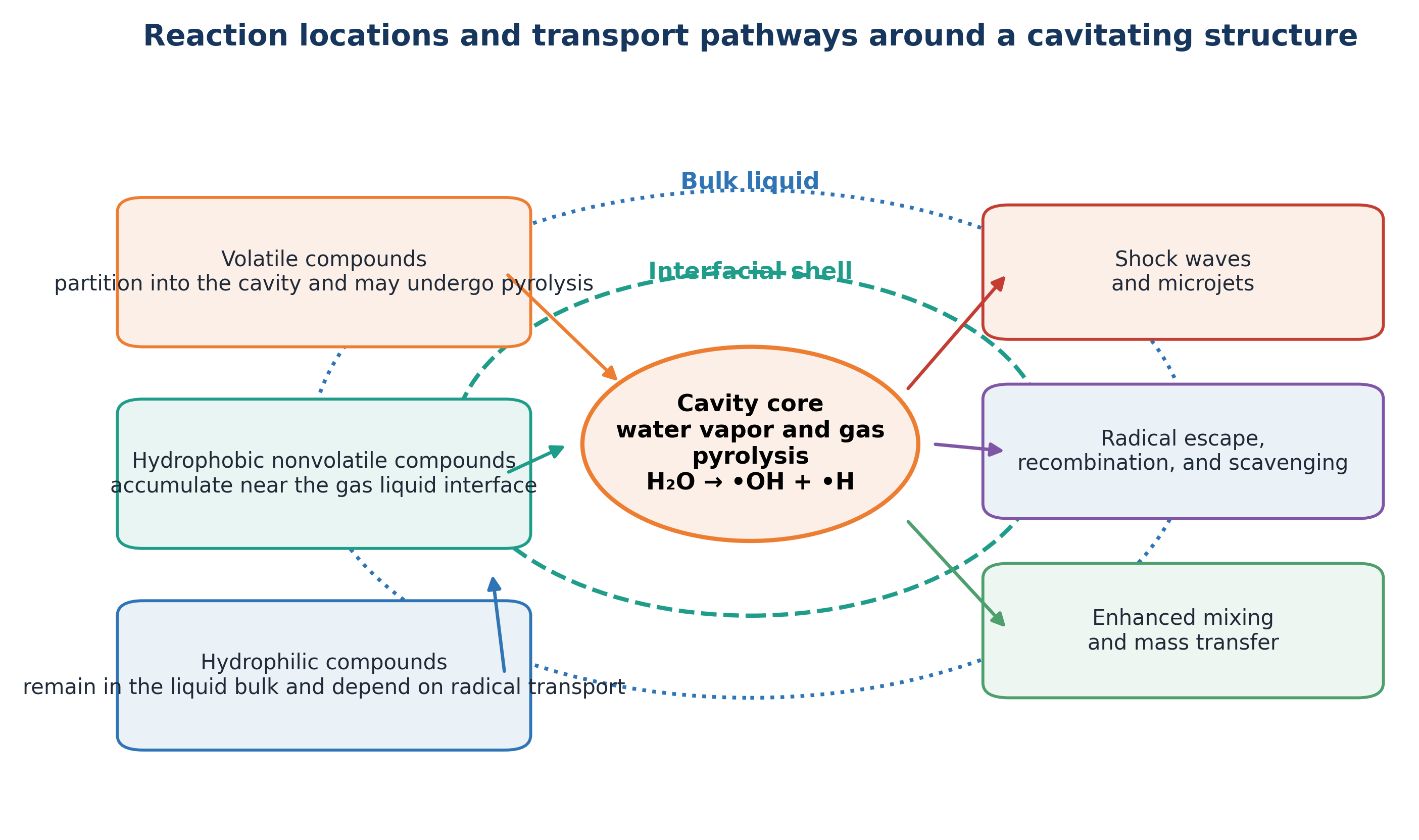
Figure 2.1. Reaction locations and transport pathways around a cavitating structure [11].
2.2 Hydraulic State, Cavity Population, and Reactor Form
For water processing, the controlling hydraulic variable is the population of cavities that experiences a productive pressure history. A sufficiently low local pressure is required for inception, but it does not independently determine chemical or biological performance. Nuclei concentration, dissolved gas, surface tension, viscosity, pressure recovery rate, cavity residence time, cloud interaction, and collapse location can cause devices with similar nominal cavitation numbers to produce different treatment outcomes [3,8,12-15].
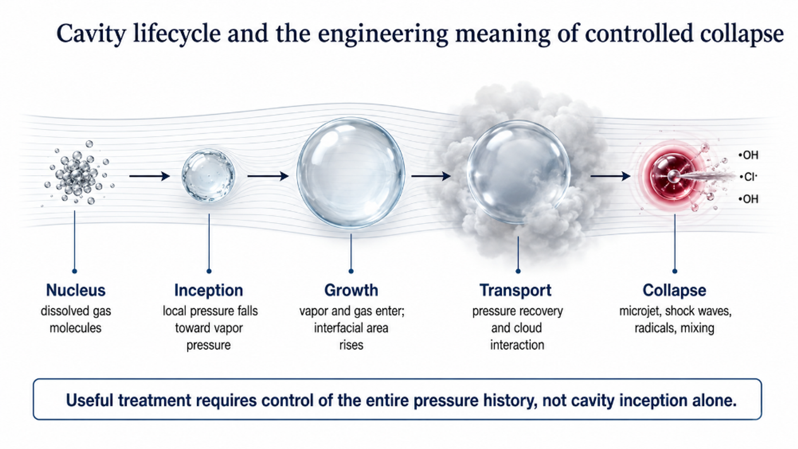
Figure 2.2. Cavity lifecycle and engineering meaning of controlled collapse [11].
Static flow through devices generate cavitation by converting pressure into velocity through an orifice, Venturi passage, nozzle, vortex element, bluff body, or jet. These devices are mechanically simple and can be installed in a recycle loop or a once through line. Their principal engineering limitations include pump duty, blockage by fibrous or coarse solids, nonuniform distribution among parallel openings, and the formation of long vapor structures when downstream backpressure is insufficient.
Dynamic devices generate repeated low pressure regions using a rotor, stator, dimpled disk, toothed surface, or narrow rotating gap. Local velocity and pressure oscillation can therefore be increased without forcing the entire plant flow through a single small constriction. This characteristic can be advantageous for sludge, concentrated industrial streams, and high throughput disinfection. The associated tradeoffs are bearings, seals, rotating clearances, vibration, torque demand, and additional wear surfaces [6-8,31,62].
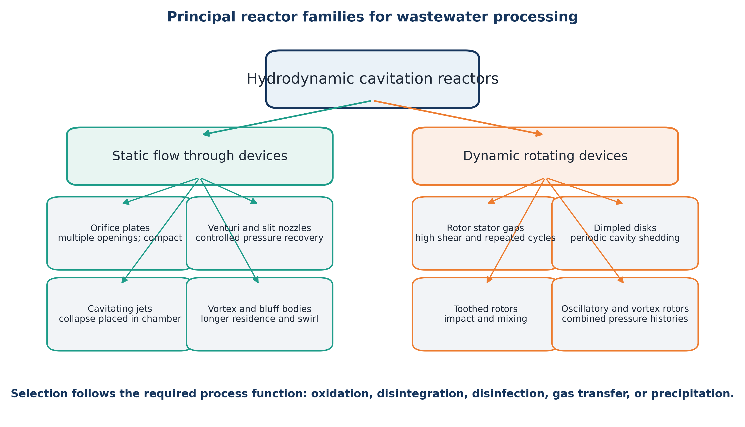
Figure 2.3. Principal reactor families used in wastewater processing [11].
Reactor selection should begin with the required process function. Oxidation requires generation of reactive species and transfer to the relevant reaction domain. Sludge pretreatment requires floc breakup, cell damage, and controlled solubilization. Disinfection may depend on pressure cycling, microjets, shear, radicals, or bulk heating. Gas transfer and precipitation applications depend primarily on interfacial renewal and mixing rather than maximum collapse intensity. Consequently, a reactor that is effective for one function should not be assumed to be optimal for another.
2.3 Cavitating Jets, Nozzles, and Controlled Collapse
Cavitating jets are useful when the collapse region must be localized within a defined chamber. A shear layer forms as liquid exits the nozzle, microscopic nuclei grow in the low pressure jet, and the cavity cloud collapses when it enters a higher pressure region or encounters a stagnation surface. Jet arrays can distribute active regions throughout a vessel, while a downstream target or collision ring can intensify collapse at a selected location [15,56,59].
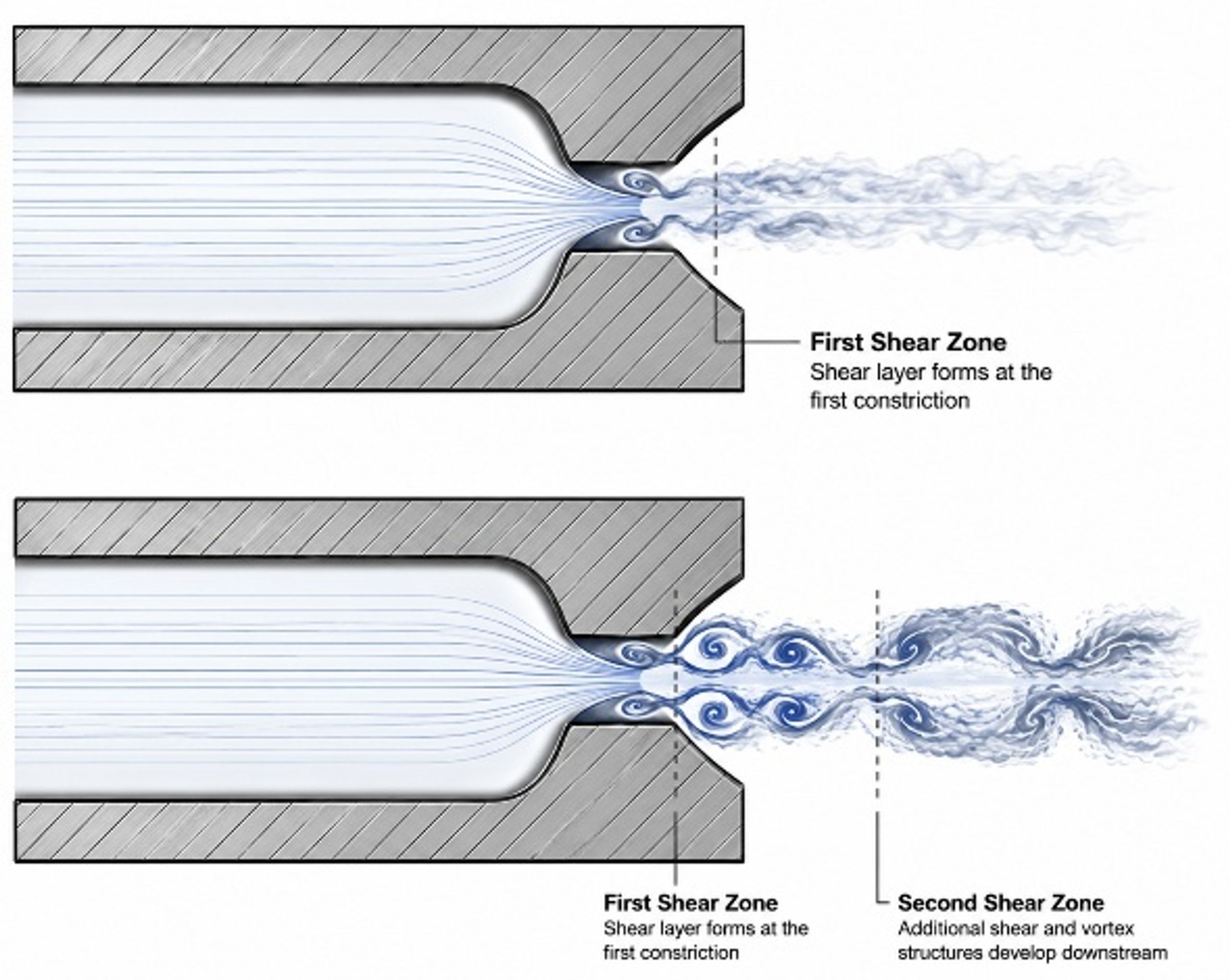
Figure 2.4. Jet forming nozzle with first and second shear zones [69].
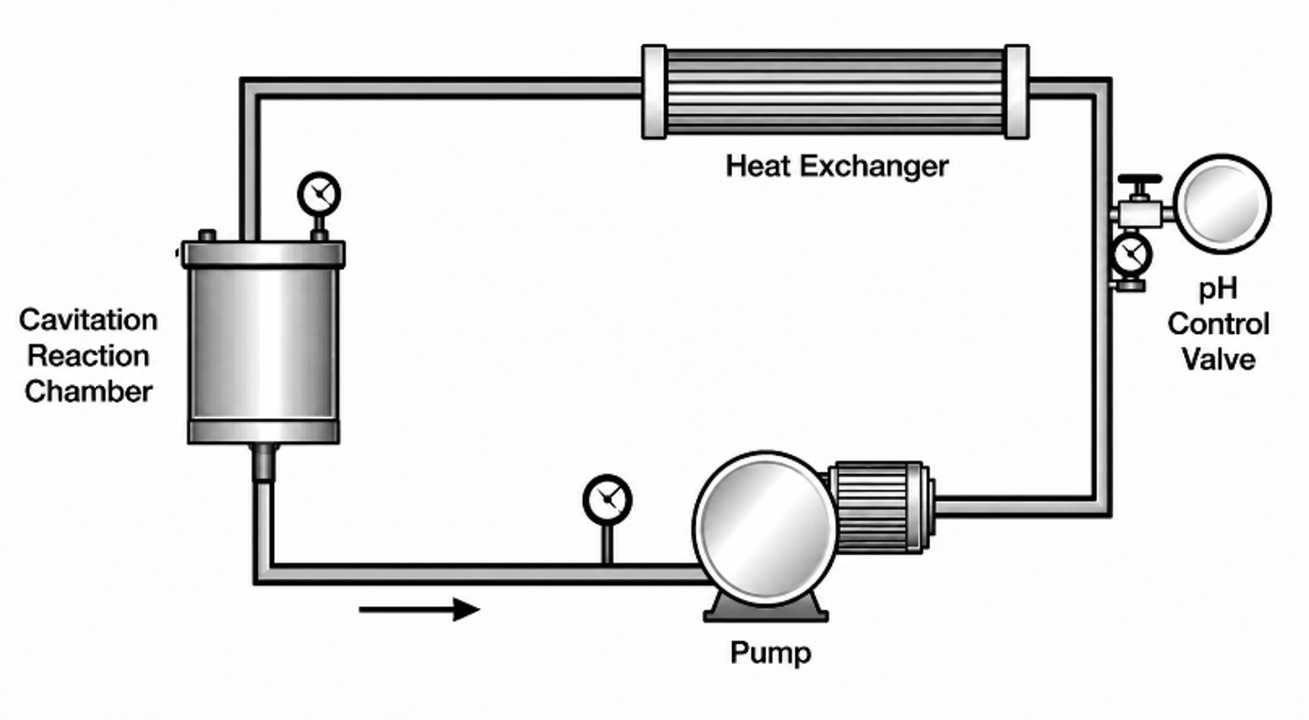
Figure 2.5. Recirculating cavitation treatment loop with reaction chamber, pump, heat exchanger, and pH control [69].
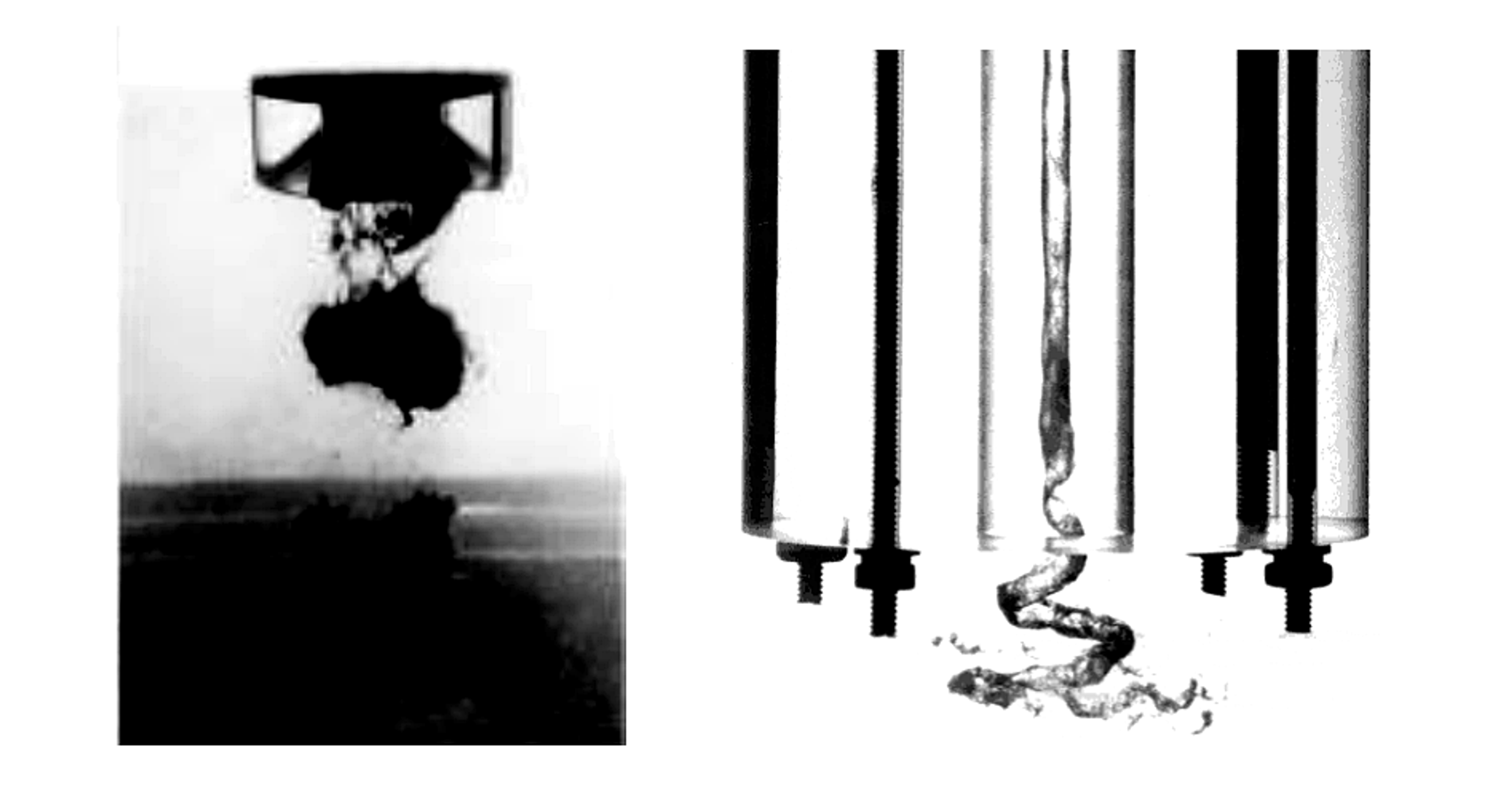
Figure 2.6. Stroboscopic views of resonant and swirling cavitating jets [17].
Kalumuck and Chahine used recirculating jet loops and multistage orifice plates with downstream stagnation surfaces to oxidize dilute p-nitrophenol. Under the reported experimental conditions, submerged cavitating jets provided approximately two orders of magnitude greater energy efficiency than the ultrasonic comparison. The authors attributed this result to broader cavitation distribution and the relatively high efficiency of hydraulic pumps. The reported ratio is study specific and should not be generalized to all reactors or contaminants [56].
Backpressure is an active design variable. Insufficient downstream pressure recovery can produce a stable or supercavitating vapor region with weak collapse. Excessively abrupt recovery, particularly on a vulnerable wall, can increase erosion, noise, and vibration. Productive operation therefore requires control of both inception and collapse, including the axial position of cloud shedding and the distance between collapse zones and sensitive equipment surfaces [9,10,15,56].
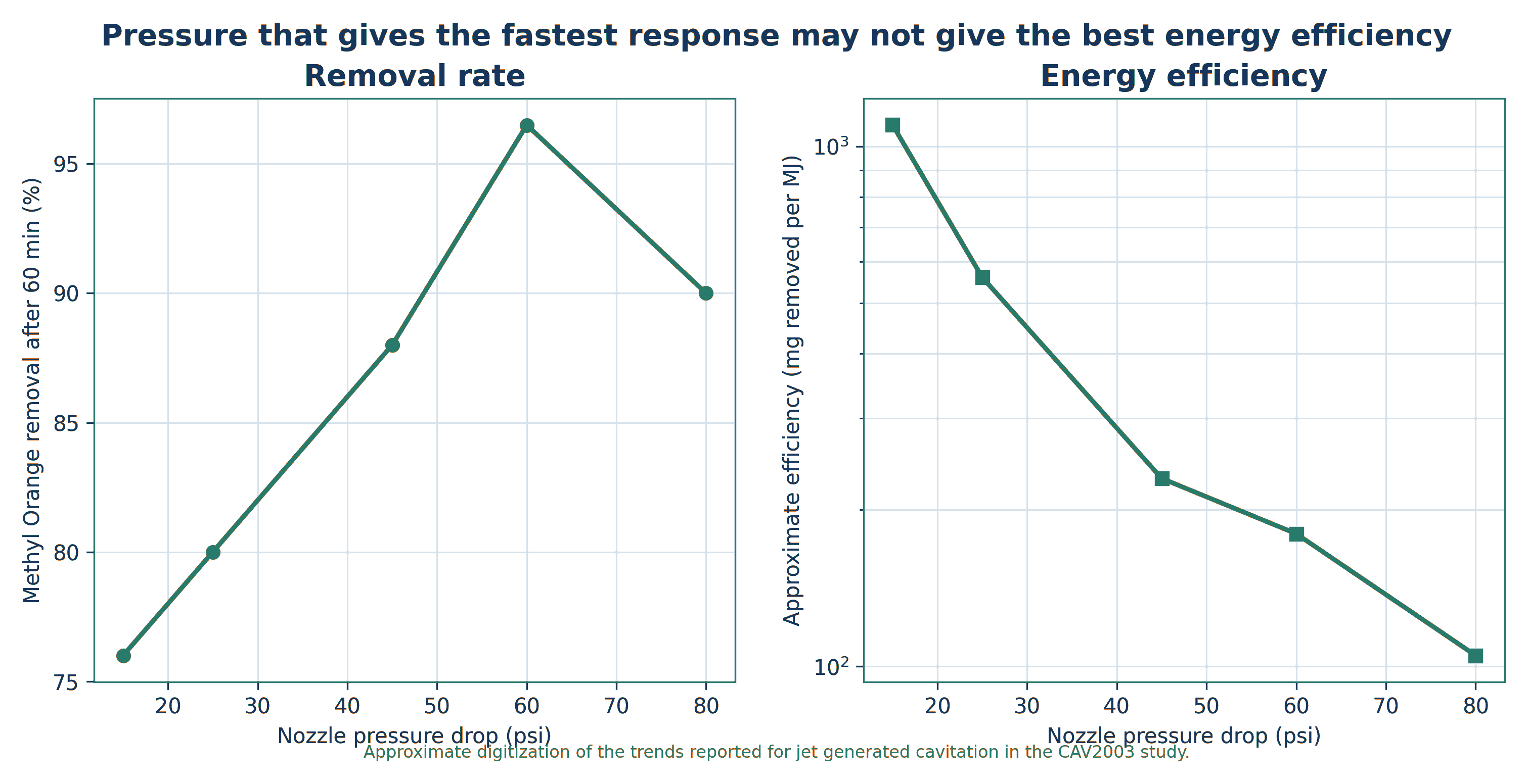
Figure 2.7. Pressure can accelerate contaminant removal while reducing hydraulic energy efficiency [17].
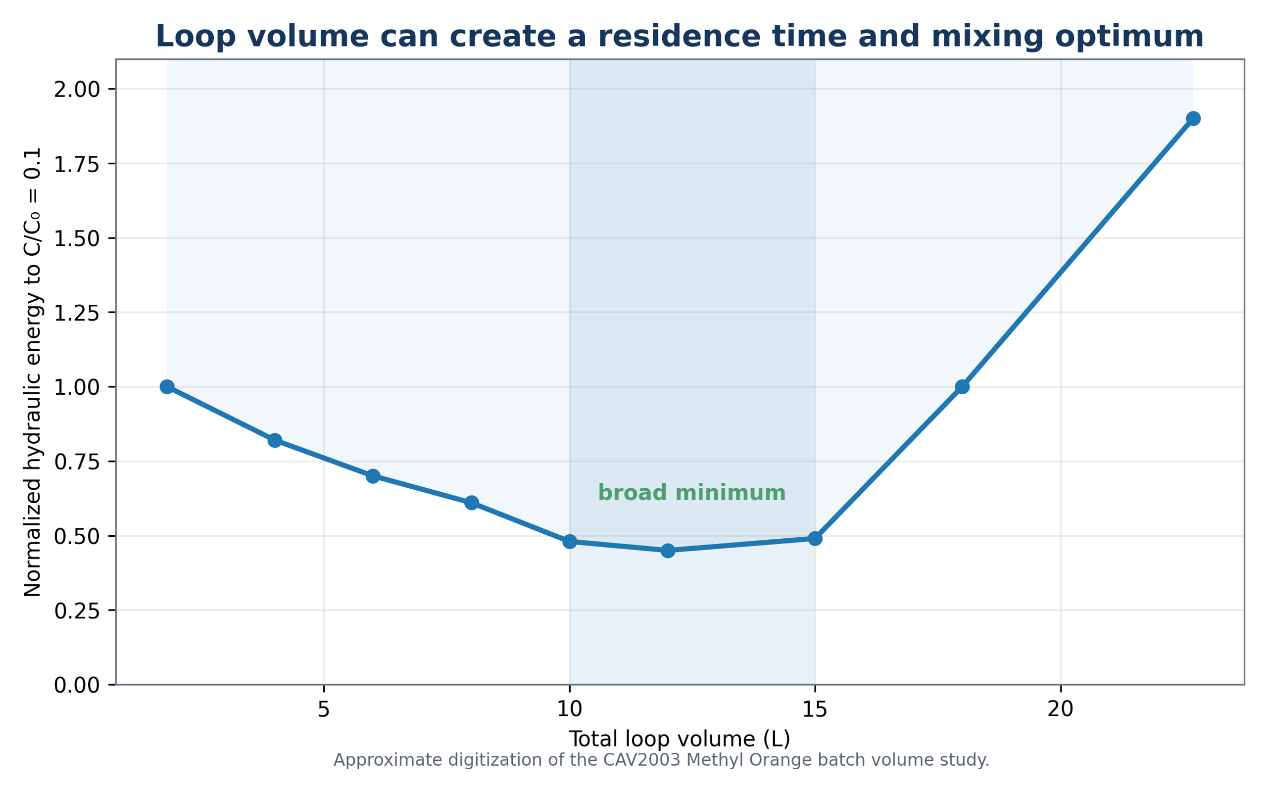
Figure 2.8. Effect of recycle loop volume on the energy required for one order of magnitude methyl orange reduction [17].