
Technical publication
Back to publications
Other
Fabrication of High Performance Catalysts by Controlled Flow Cavitation
okozyuk.com
Published
Read complete publication for whole-document Find and printing. Browser Find and native printing on this reader include only loaded content.
3 Reactor Architecture and Operating Envelope
The original research employed two principal equipment families. CaviPro research systems operated at high pressure and commonly used two restrictions in series. The first restriction created a low pressure jet and cavitation cloud. The second restriction, or an adjustable downstream valve, controlled pressure recovery and the probable collapse location. CaviMax systems used a larger single restriction at lower pressure and higher volumetric flow. Production scale machines increased active flow capacity rather than simply increasing batch volume [1-7].
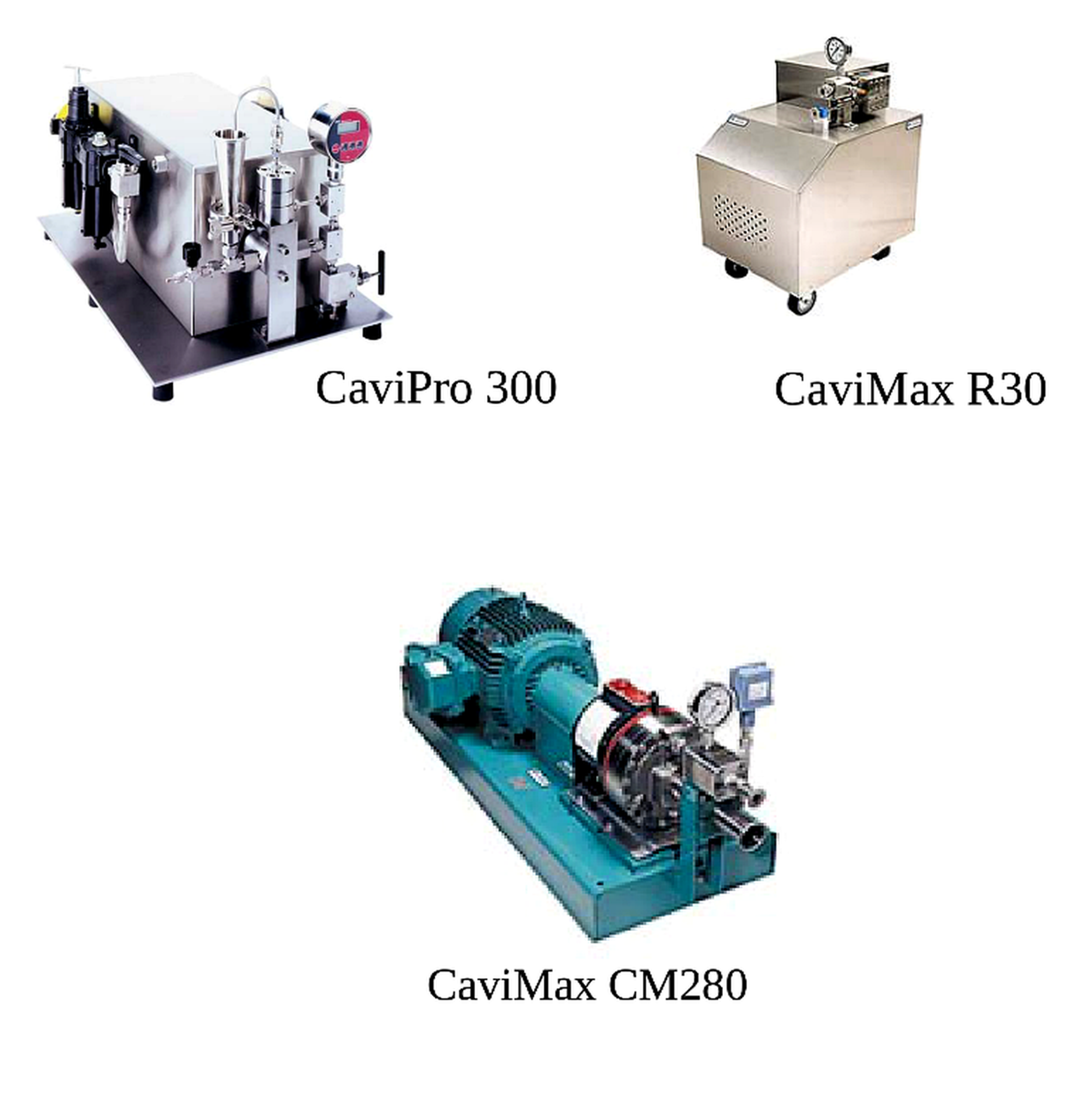
Figure 3.1. Laboratory and production scale cavitation equipment: CaviPro 300, CaviMax R30, and CaviMax CM280 [6].
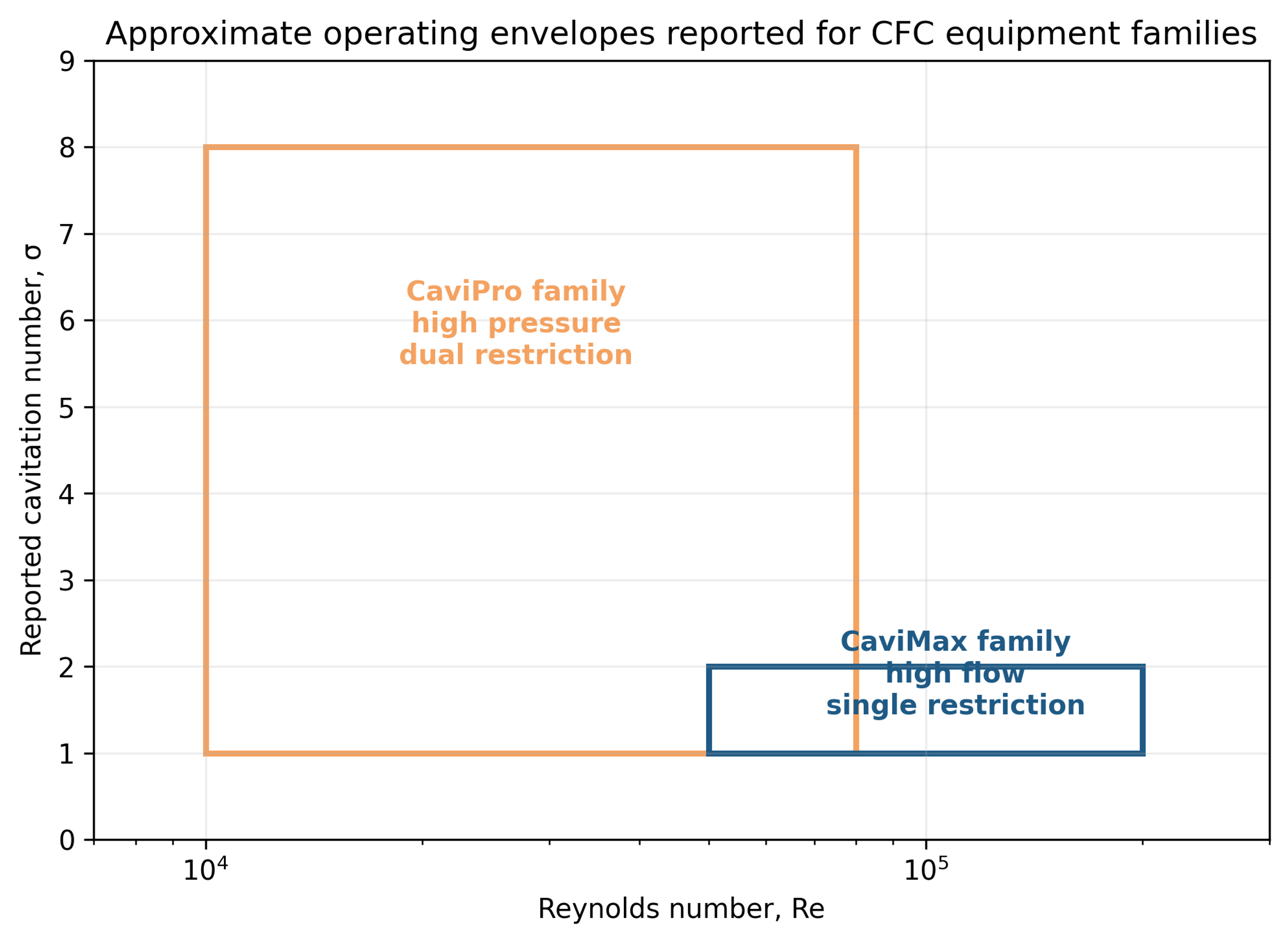
Figure 3.2. Approximate Reynolds number and cavitation number envelopes reported for the CaviPro and CaviMax families. The rectangles summarize ranges, not product equivalence. [6,7,23-27].
Table 3.1. Representative operating characteristics reported for CFC systems
| Characteristic | CaviPro family | CaviMax family | Design implication |
|---|---|---|---|
| Configuration | Dual restriction with adjustable pressure and recovery | Single restriction with nominally high flow | The same cavitation number can represent different bubble and residence histories |
| Pressure range in source materials | Approximately 6–206 MPa, model dependent | Approximately 0.7–6.9 MPa | Pressure rating alone does not define treatment |
| Reported Reynolds number | About 10,000–80,000 | About 50,000–200,000 | High flow increases renewal frequency and active volume |
| Reported cavitation number | About 1–8 | About 1–2 | Pressure reference location must be documented |
| Primary controls | First and second restriction, upstream pressure, back pressure, flow, passes | Restriction, upstream pressure, back pressure, flow, recycle time | Variables are coupled and require designed experiments |
| Scale emphasis | High intensity research and small flow | Lower pressure, larger flow, production development | Scale by product equivalence rather than by nominal pressure |
The practical operating window is governed by more than the pump pressure rating. A very small passage can increase velocity but can also cause feed pulsation, low throughput, plugging, and severe erosion. Higher solids loading may increase particle-bubble contact while attenuating pressure fluctuations and altering rheology. Increased back pressure can stabilize a compact collapse zone, whereas excessive recovery pressure can suppress cavity growth. A robust design therefore requires pressure transducers before and after each restriction, a calibrated flow meter, bulk temperature measurement, and a defined back pressure control point.
Table 3.2. Control variables, favorable responses, and adverse responses
| Variable | Possible favorable response | Possible adverse response | Recommended monitoring |
|---|---|---|---|
| Upstream pressure | Faster micromixing and stronger fragmentation | Pump heating, erosion, excessive nucleation | Pressure, flow, temperature, wear metals |
| First restriction | Controlled inception and gel breakup | Plugging and unstable feed pressure | Differential pressure and inspection |
| Second restriction or back pressure | Collapse near suspended particles and shorter cloud | Cavitation suppression and severe localized erosion | Recovery pressure and acoustic signal |
| Flow rate | High throughput and frequent renewal | Insufficient exposure per pass | Calibrated flow and loop volume |
| Temperature | Lower viscosity and faster reaction | Vapor cushioning, ripening, solvent loss | Continuous inlet and outlet temperature |
| Solids loading | Higher productivity and collision frequency | Nonuniform exposure, abrasion, non-Newtonian flow | Density, viscosity, pressure loss, settling test |
| Passes | Improved mixing and agglomerate control | Overprocessing and energy penalty | Total volume processed and residence distribution |