
Technical publication
Back to publications
Other
Engineering Calculations for Rotor-Stator Mixers
okozyuk.com
Published
Updated
Read complete publication for whole-document Find and printing. Browser Find and native printing on this reader include only loaded content.
6 Flow in the radial gap
6.1 Cylindrical Couette reference solution
A reference solution for the gap is steady laminar cylindrical Couette flow between an inner cylinder rotating at angular speed and a stationary outer cylinder. For concentric smooth surfaces, no slip, negligible end effects, and no radial or axial throughflow, the tangential velocity is
In the narrow gap limit , the tangential velocity profile approaches a linear variation across the clearance. The corresponding nominal shear rate is
For a Newtonian liquid, multiplication by dynamic viscosity gives the nominal viscous shear stress:
The nominal shear rate and stress provide comparison metrics for preliminary screening. Local deformation also includes spatial variations near teeth, slot edges, stagnation regions, recirculation zones, and jets. Partial fluid rotation can reduce the gradient in some regions while increasing it near a stationary surface. The smooth Couette solution can also lose stability to secondary motion as rotational forcing increases. Its applicability therefore depends on the radius ratio, operating regime, end conditions, and throughflow, as well as the nominal gap Reynolds number [14].
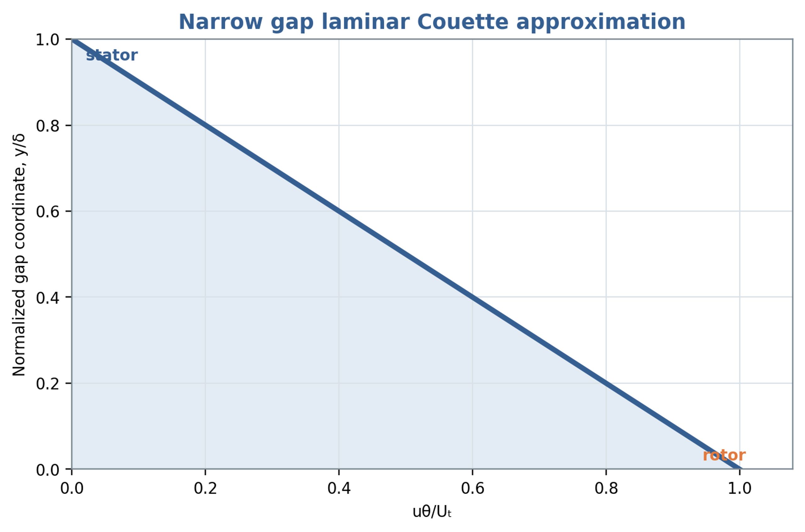
Figure 6.1. Linear tangential velocity profile in the narrow gap Couette approximation, with a moving rotor wall and stationary stator wall.
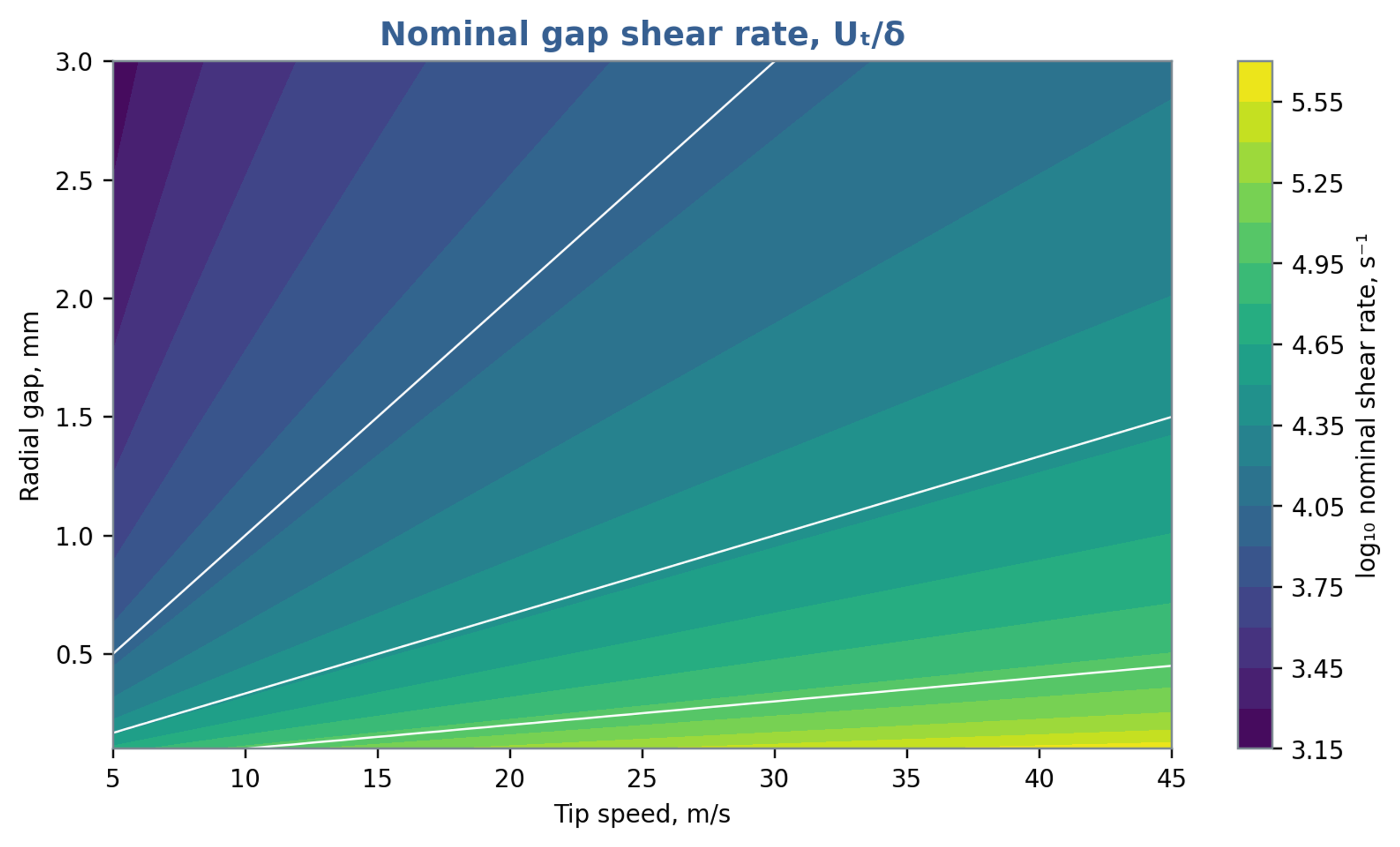
Figure 6.2. Nominal gap shear rate as a function of tip speed and radial clearance, calculated from Equation (6.2). The map represents a geometric screening estimate.
6.2 Gap torque and viscous power
For an inner cylinder with active length , integration of the laminar wall shear stress gives the torque magnitude required to maintain its rotation:
The associated rate of viscous energy transfer is
In the narrow gap limit, Equation (6.4) becomes . The approximation exposes the strong dependence on rotor radius and the inverse dependence on clearance. It is a reference solution for the specified laminar geometry. In a toothed or slotted head, throughflow, secondary circulation, turbulence, roughness, and periodic restriction alter the wall stresses and torque. The result should therefore be used to identify trends and check orders of magnitude, with measured torque providing the final power basis.
Chervyakov and Yudaev develop a broader power balance that separates energy imparted to the flow, viscous losses in radial and axial gaps, and mechanical losses [1]. This decomposition connects power demand to identifiable regions of the apparatus. Because the detailed expressions depend on geometry and flow regime, the present analysis retains the physical structure of the balance and reserves quantitative validation for torque and hydraulic measurements.
6.3 Radial throughflow and pressure
If mean volumetric flow passes radially through an annular region of active height , an average velocity based on the open portion of the circumference is
where denotes the effectively open circumferential fraction on the same averaging basis as the flow. During slot passage, the velocity field is spatially nonuniform, with localized jets and pressure gradients in both radial and circumferential directions. Equation (6.6) provides an area based transport estimate and a comparison with the tangential speed. It does not resolve individual jets, local reverse flow, or correlations between instantaneous open area and discharge.
The tangential gap Reynolds number may be formed from and , while a throughflow Reynolds number uses and an appropriate hydraulic diameter. Both should be reported when radial transport is substantial. A flow with strong tangential motion and weak radial transport can have a different stress field and residence distribution from a high velocity radial jet at the same rotor tip speed.
6.4 Oscillatory boundary layers and leakage
Passage of a slot can change local radial pressure and velocity over a fraction of a millisecond. At a large gap based Womersley number, rapid viscous adjustment is confined mainly to boundary layers, while the interior responds through inertia. Pressure, flow, and wall stress can consequently exhibit appreciable phase differences. A steady Couette calculation may approximate one contribution to the cycle average while failing to represent the instantaneous torque and stress maxima.
When the principal opening is covered, the remaining clearance provides a leakage path. The minimum effective area consequently helps determine the achievable modulation depth. Increased leakage can weaken pressure pulsation, while a larger mechanical clearance reduces sensitivity to runout and thermal growth. Gap selection should therefore balance deformation rate, pressure modulation, pumping, manufacturing tolerances, erosion, and cleanability within a common hydraulic and mechanical analysis.