
Technical publication
Back to publications
Other
Engineering Calculations for Rotor-Stator Mixers
okozyuk.com
Published
Updated
Read complete publication for whole-document Find and printing. Browser Find and native printing on this reader include only loaded content.
5 Unsteady flow in working passages
5.1 Conservation equations
Mass conservation provides the starting point for the unsteady flow model. Retaining density variation gives the continuity equation for a weakly compressible liquid:
For a Newtonian liquid of spatially uniform viscosity, with dilatational viscous stresses neglected at leading order, the momentum equation in an inertial reference frame is
Transformation to a reference frame rotating with the rotor introduces centrifugal and Coriolis accelerations. Chervyakov and Yudaev formulate the problem using the cylindrical Navier Stokes equations and then develop approximations for flow in rotating rectangular channels [1]. If circumferential relative motion and transverse variations are neglected, the radial component can be represented by
The centrifugal term contributes to outward acceleration, whereas the pressure gradient responds to the imposed boundary pressures and the changing hydraulic restriction. Equation (5.3) retains only radial viscous derivatives. It therefore does not resolve the wall friction associated with velocity gradients across the width and height of an actual channel. Those effects require a resolved cross section or a separate resistance closure. Periodic variation of the downstream opening repeatedly accelerates and decelerates the liquid even when shaft speed is constant.
5.2 Hydraulic inertance and resistance
For preliminary calculations, the distributed channel problem can be reduced to a hydraulic element containing inertance, linear viscous resistance, and a nonlinear local loss. The governing balance for one modeled passage is
where is the instantaneous volumetric flow, is hydraulic inertance, is linear hydraulic resistance, is a local loss coefficient, is the reference flow area, and is the net driving pressure, including the centrifugal contribution and imposed system pressures. The signed nonlinear term opposes either direction of flow. For a liquid column of effective length and fixed reference area , the inertance is
For fully developed laminar flow between parallel stationary surfaces separated by a small gap , with channel width satisfying , the linear hydraulic resistance is approximately
The nonlinear term generally becomes important for short restrictions and rapidly moving jets. The coefficient depends on edge geometry, passage thickness, swirl, contraction, expansion, and the presence of cavities or gas. Its calibration should use the same reference area and pressure locations as the model. A resistance derived for fully developed laminar flow is insufficient when entrance effects or oscillatory boundary layers dominate. Periodic overlap is preferably introduced through the restriction, while the inertia of the connected liquid columns is modeled separately.
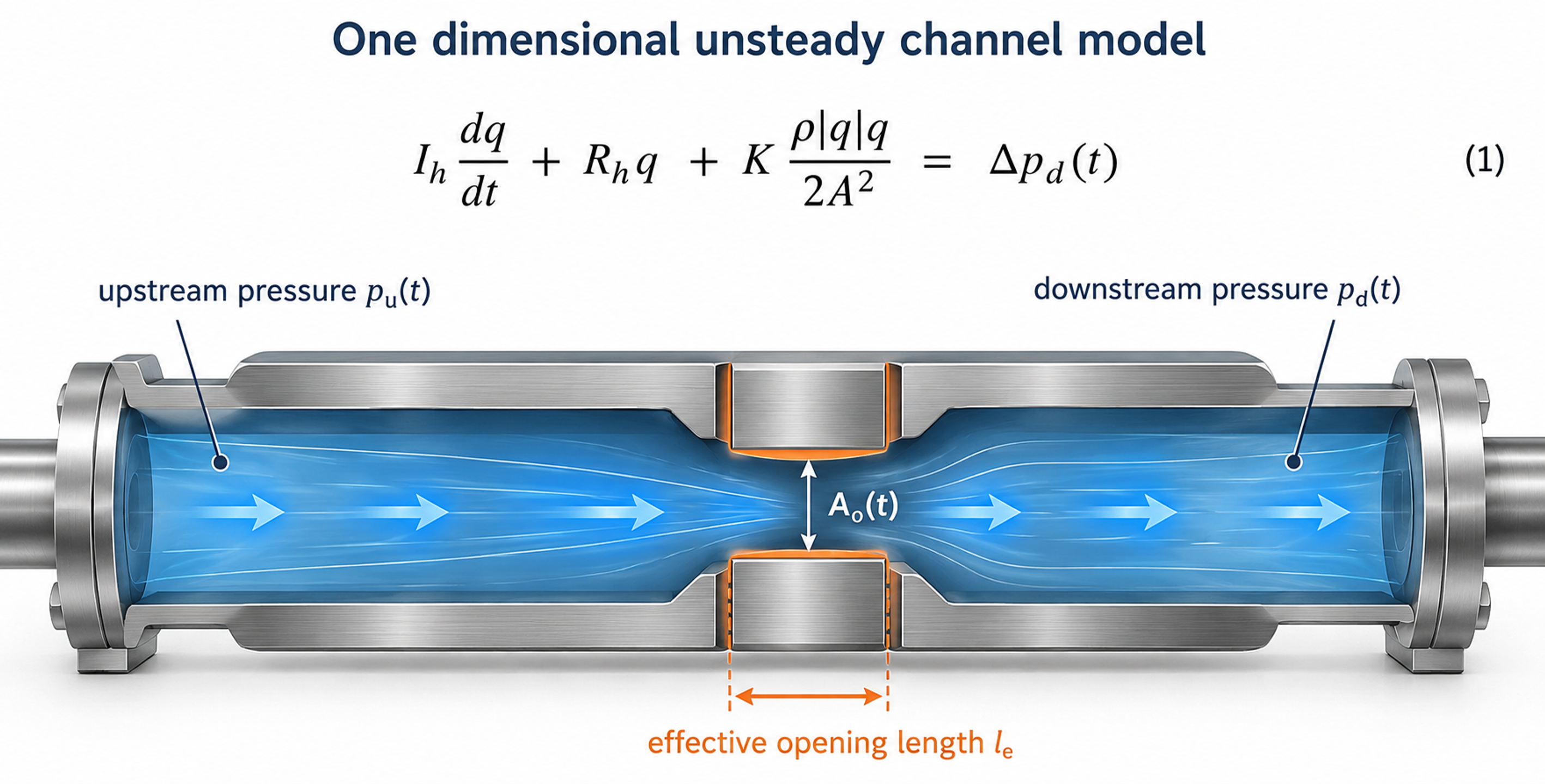
Figure 5.1. Control volume and lumped hydraulic representation of one working passage. The inlet and outlet pressures, effective opening and liquid column length define the model boundary. Diagram based on [1, 8, 13].
5.3 Time varying orifice relation
If the opening behaves as an orifice, the upstream pressure exceeds the downstream pressure, and reverse flow is absent, the instantaneous discharge has the quasi steady approximation
Equation (5.7) applies when the discharge adjusts rapidly relative to the opening period. Significant liquid inertia, rapid area variation, cavitation, or interaction with pressure waves can invalidate this approximation. An improved preliminary model uses Equation (5.7) to express the pressure loss across the restriction and includes that loss once in Equation (5.4). The inertance term then determines the acceleration and phase of the flow. Imposing the full quasi steady discharge and the full transient balance independently across the same pressure difference would overconstrain the model and can count the restriction loss twice.
For a liquid column represented by an effective length, the pressure required for temporal acceleration is estimated by
For an abrupt velocity change in an ideal one dimensional liquid column, the Joukowsky relation provides a limiting pressure change for the generated wave:
Here, is the wave speed of the liquid and its compliant containment. Application of Equation (5.9) requires a justified velocity change and a closure time short relative to the relevant acoustic travel time. Rotor stator passages usually retain leakage and distributed flow paths, while entrained gas and structural compliance alter the wave speed. Reflections and wave superposition can also change subsequent pressure maxima. The relation is consequently a transient reference estimate, rather than a universal upper bound for every pressure peak in a connected mixing system.
5.4 Dimensionless measures of unsteady flow
The Reynolds number compares convective inertia with viscous transport using a declared reference velocity and characteristic hydraulic dimension :
The Strouhal number compares the characteristic convective transit time with the period of flow modulation:
The Womersley number expresses the square root of the ratio of oscillatory inertia to viscous diffusion on the selected length scale:
The corresponding penetration depth of an oscillatory viscous boundary layer is
When , viscous diffusion acts across the selected length during each cycle, and the velocity profile can adjust closely to the forcing. When , an inertia dominated interior and thin oscillatory boundary layers may develop. The length convention must be stated explicitly because use of slot half width, full gap width, or hydraulic radius gives different numerical values. These groups identify relevant transport mechanisms; they do not establish a universal transition criterion for every rotor stator geometry.
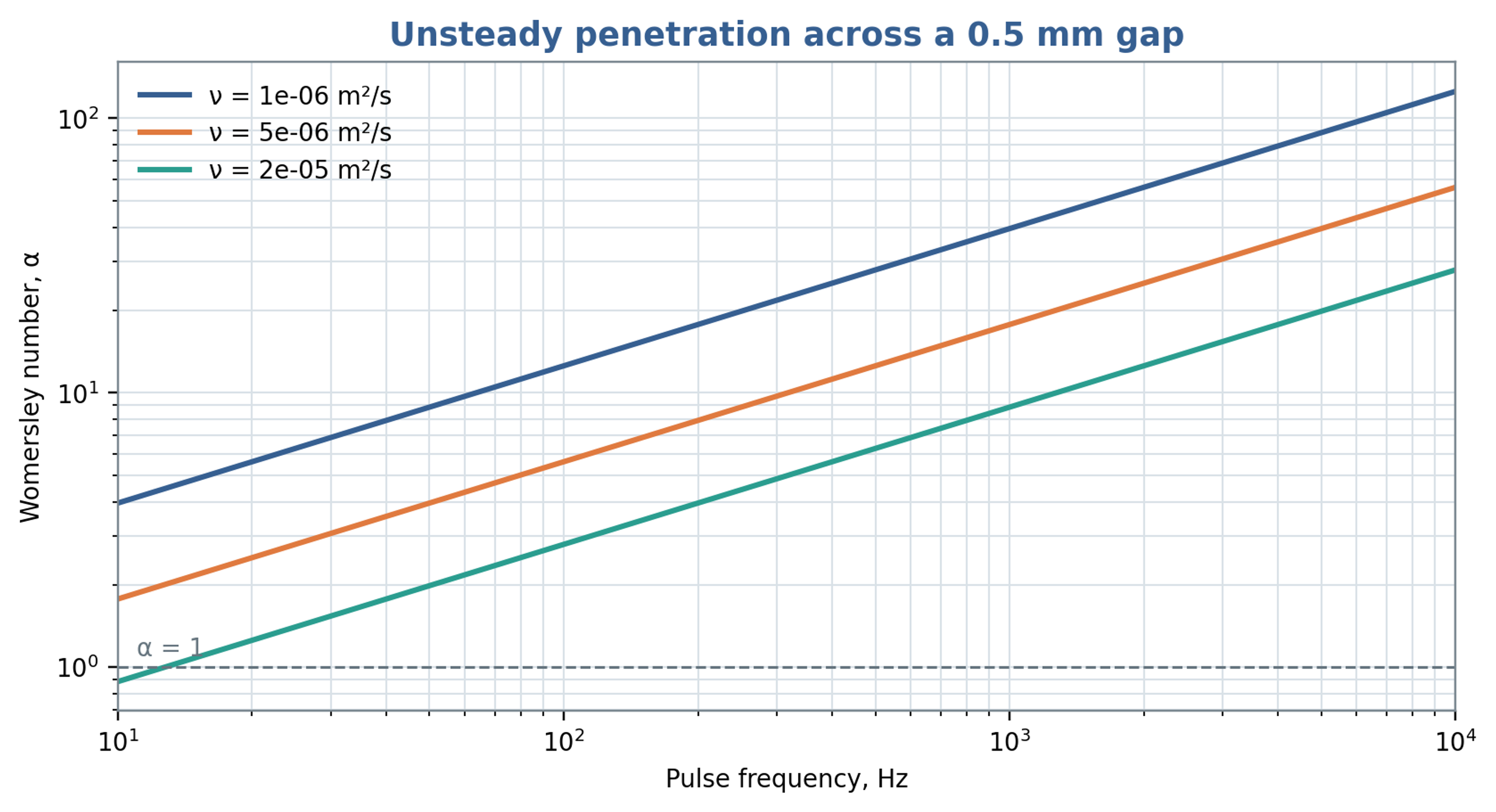
Figure 5.2. Womersley number for a characteristic length of 0.50 mm over pulse frequency and kinematic viscosity, calculated from Equation (5.12).
Table 5.1. Interpretation of principal unsteady flow groups
| Group | Small value | Large value | Design consequence |
|---|---|---|---|
| Viscous forces dominate | Inertia becomes important; transition depends on geometry | Determines whether laminar resistance or inertial loss is more appropriate | |
| Slow modulation relative to convection | Rapid modulation | Controls whether a quasi steady or strongly unsteady model is needed | |
| Velocity profile adjusts through the section during a cycle | Oscillatory boundary layers and phase lag | Important for pulse amplitude and viscous loss | |
| Small pressure change relative to dynamic pressure | Strong restriction or pressure generation | Useful for comparing hydraulic stages |