
Technical publication
Back to publications
Other
Engineering Calculations for Rotor-Stator Mixers
okozyuk.com
Published
Updated
Read complete publication for whole-document Find and printing. Browser Find and native printing on this reader include only loaded content.
3 Working geometry
3.1 Feature count and circumferential pitch
For a cylindrical rotor of outside diameter with equally spaced features, the circumferential pitch is
If the circumferential clear opening is , the tooth or bridge width is
Equivalent definitions apply to the stationary member. Rectangular stator slots of width and active height have the total geometric area
For an ideal uniform pattern, the circumferential open fraction is
Equation (3.4) defines geometry. Hydraulic contraction, wall thickness, upstream swirl, blockage, gas cavities and uneven flow distribution affect the effective discharge area. The product is commonly used in an orifice representation, with determined from an applicable correlation or a calibration. The coefficient must not be interpreted as a change in the manufactured opening dimensions.
At fixed diameter, a larger feature count reduces the circumferential pitch. If opening width is held constant, the open fraction increases and the intervening bridges become narrower. If open fraction is held constant, both opening and bridge widths decrease. The accompanying increase in passage frequency must be considered together with drag, clogging, manufacturing tolerances and wear. The examples in US5632596A include 45 radial grooves at 8 degree intervals and demonstrate that tooth height and the number of concentric rows can vary independently of outside diameter [5].
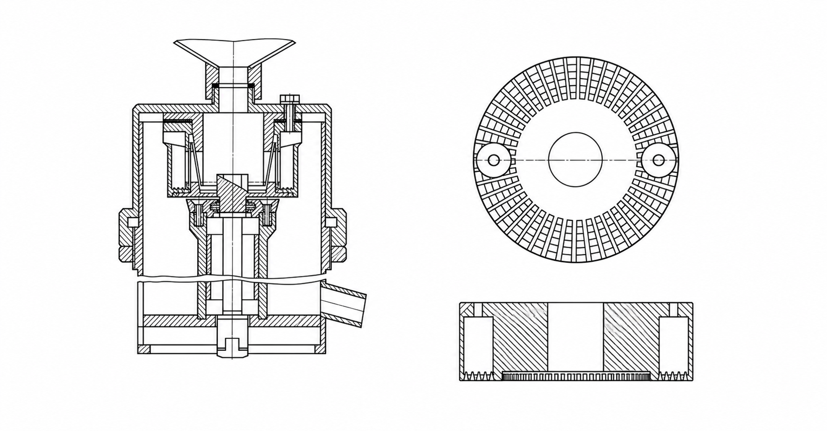
Figure 3.1. Rotor-stator architectures shown as simplified technical illustrations. Left, the apparatus disclosed in SU829155A1. Right, plan and sectional views of the low profile toothed stator disclosed in US5632596A.
Table 3.1. Geometric variables and their first order effects
| Variable | Increase generally causes | Countervailing effect or risk |
|---|---|---|
| Rotor diameter | Higher tip speed at fixed rpm, larger wetted area, greater pumping potential | Strong increase in torque and power; larger shaft and bearings |
| Rotor feature count | Higher local passage frequency and edge density | Smaller bridges, clogging, manufacturing tolerance sensitivity |
| Stator opening count | More distributed jets and larger potential area | Reduced individual jet momentum if total flow is fixed |
| Slot width | Larger open area and longer opening duration | Lower local velocity and weaker pressure modulation at the same flow |
| Slot depth or active height | Larger flow area and wetted surface | Higher drag and larger trapped volume |
| Radial gap | Lower nominal shear and contact risk | More leakage, reduced pressure modulation, weaker local stress |
| Number of rows | More repeated energy input events | Greater pressure loss, heat, residence time, and cleaning difficulty |
3.2 Radial clearance and manufacturing allowance
For rotor radius and stator radius , the nominal radial clearance is
The dimensionless clearance may be expressed as or . The nominal drawing value differs from the smallest clearance reached during operation. Shaft runout, bearing play, housing deflection, thermal expansion, eccentric assembly and entrained particles can reduce the local gap. A tolerance assessment should consequently include both assembly conditions and the expected temperature distribution during operation.
Reducing the gap increases the nominal velocity gradient and viscous stress while restricting leakage between adjacent passages. It can strengthen area modulation, but it can also increase drag, heating, erosion and the probability of contact. Chervyakov and Yudaev explicitly account for flow through finite clearances while the main stator channel is covered [1]. This treatment is relevant because complete hydraulic closure is generally inconsistent with nonzero radial or axial leakage paths.
Clearance selection should begin with the manufacturing and mechanical limits and then be evaluated hydraulically. The selected gap must remain achievable under the combined effects of speed, load, temperature and wear. Predictions based on a clearance smaller than the maintained operating gap will overstate nominal shear and the degree of passage closure.
3.3 Time dependent overlap area
A compact representation of the periodic effective opening is
where denotes the mean opening, is an area modulation index, is a periodic function of zero mean and unit characteristic amplitude, is the selected overlap frequency, and is the phase. A sinusoidal function supports linear analysis, whereas triangular or trapezoidal functions can better approximate rectangular openings. Piecewise area models can account for progressive exposure and finite leakage [1]. The selected representation must reproduce the minimum, maximum and mean areas, together with the opening duration; it must also remain nonnegative throughout the cycle.
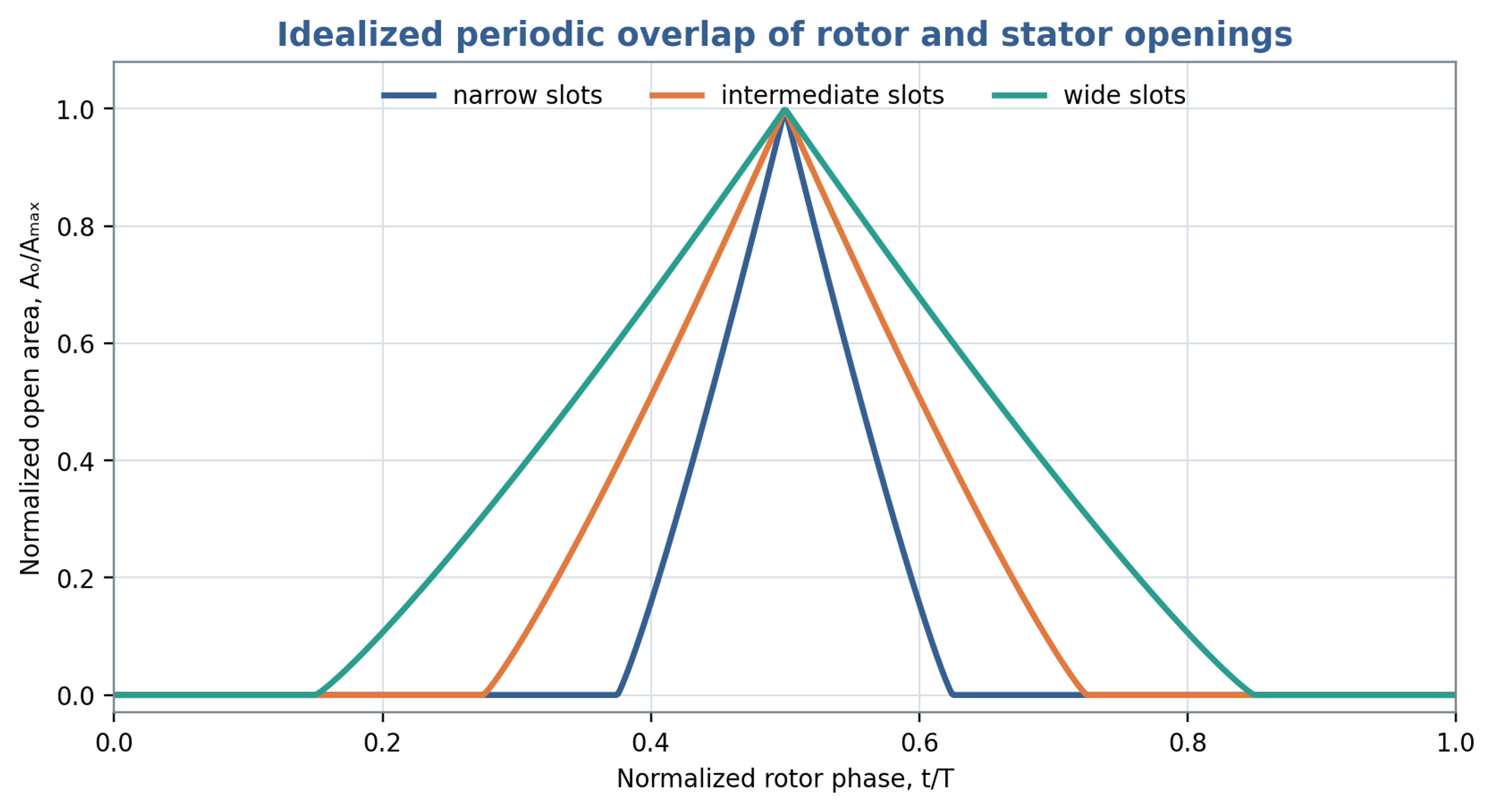
Figure 3.2. Normalized overlap area for narrow, intermediate and wide opening windows. These idealized curves illustrate geometric modulation rather than measured apparatus performance.
The area waveform influences both jet acceleration and the harmonic content of the forcing. Narrow exposure windows concentrate the opening event into a shorter part of the cycle. Wider windows extend the period of flow and generally reduce the relative importance of rapid opening and closure. Figure 3.2 illustrates these geometric effects. The preferred configuration depends on the required throughput, pressure modulation, thermal limit and resistance to blockage.
3.4 Evidence from systematic geometry changes
Stator geometry should be assessed through controlled changes in both the perforations and the inlet boundary. John et al. used computational models, supported by measured power, to relate workhead dimensions to flow and power characteristics. Within the limited hole sizes investigated at constant total opening area, the hole hydraulic radius did not independently change one fitted power and flow coefficient. This result does not make hole size irrelevant for arbitrary screens. The authors identified stronger fluctuations as a reason to use transient calculations or several rotor positions when extending the hole size range. The engineering implication is to document total opening area, individual passage dimensions and inlet configuration together when comparing heads [12].