
Technical publication
Back to publications
Other
Engineering Calculations for Rotor-Stator Mixers
okozyuk.com
Published
Updated
Read complete publication for whole-document Find and printing. Browser Find and native printing on this reader include only loaded content.
2 Calculation framework and model boundaries
The calculation proceeds from geometry and kinematics to hydraulics, energy conversion, operating limits and validation. Geometric analysis determines the active radii, pitch, clearances and time dependent openings. Hydraulic analysis then estimates the mean flow and the fluctuations within passages and gaps. Torque, pressure and flow define the power balance, from which specific energy and heating can be evaluated. The final stage compares these predictions with measured pressure, shaft load, temperature and product properties.
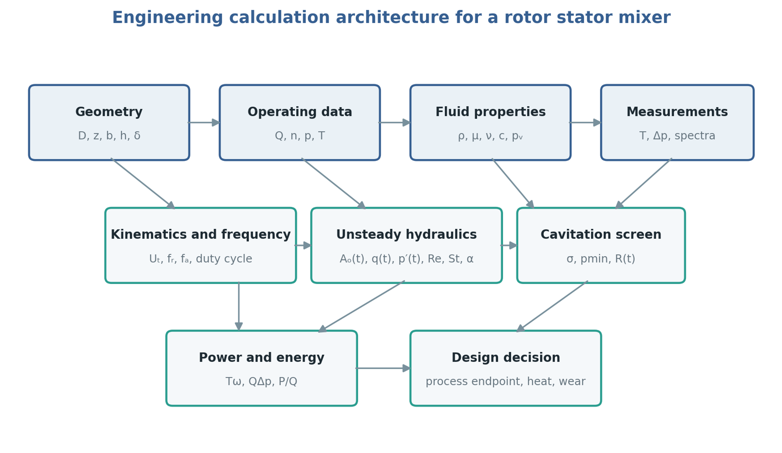
Figure 2.1. Calculation structure linking geometry, operating conditions, fluid properties and measurements to hydraulic and energy analysis. Diagram synthesized from the methods in [1, 7, 8, 9, 10].
The control volume determines the meaning of each calculated power or pressure difference. In batch operation it may enclose the working head or the entire vessel. In an inline system it may enclose the mixer housing or a larger recirculation circuit containing valves, pipework and a heat exchanger. A pressure fluctuation measured close to the stator can be attenuated before reaching a remote gauge, while a piping resonance can amplify a selected harmonic. The volume, compliance and hydraulic resistance of the external circuit should therefore be included when they influence the transient response.
The preliminary models use the following assumptions, which must be matched to the selected operating regime.
Mean flow and viscous shear are evaluated for a Newtonian liquid with negligible density variation.
Weak compressibility is retained when estimating pressure waves and rapid hydraulic transients.
The nominal rotor and stator surfaces are concentric, with a uniform working clearance.
A sharp edged orifice approximation is used for openings unless a measured discharge coefficient is available.
Fluid properties are evaluated at a stated process temperature and composition.
Cavitation screening uses absolute pressure and is checked against measurements or a validated transient model.
Power and flow correlations are applied within their demonstrated geometric and hydrodynamic ranges.
Constitutive and flow models require additional treatment for non Newtonian or viscoelastic products, substantial gas fractions, concentrated slurries, flexible components and developed cavitation. In these cases the same calculation structure remains useful, but its coefficients and closure relations require representative experiments or resolved numerical analysis. Mechanical integrity and product performance must be assessed alongside the hydraulic predictions.
Table 2.1. Calculation levels and appropriate uses
| Level | Method | Appropriate use | Main limitation |
|---|---|---|---|
| Screening | Tip speed, nominal shear, open area, cavitation number, | Early selection and test matrix design | Does not resolve local flow or pressure |
| One dimensional transient | Hydraulic inertance, resistance, time varying opening, pressure source | Pulse amplitude, phase, and system interaction | Requires calibrated loss and compliance terms |
| Three dimensional transient or periodic CFD | Sliding mesh or resolved rotor position | Local jets, wakes, pressure minima, torque | Computational cost and turbulence or cavitation model uncertainty |
| Full experimental characterization | Synchronized torque, pressure, flow, temperature, spectra, product response | Design validation and scale up | Apparatus and fluid specific |
2.1 Extension to fluids with yield stress
The constant viscosity approximation requires reconsideration when the processed material exhibits yield stress or strong shear dependence. Ayas et al. combined experiments with laminar computational modeling for a collagen solution represented by a Herschel and Bulkley constitutive relation in a particular inline mixer. They determined power and characteristic shear coefficients and examined how axial clearance affected the shear distribution. A clearance change could modify the local shear characterization while producing little change in total power over the investigated range. Their results show why integral power alone is insufficient to describe treatment uniformity in such fluids. The fitted coefficients and small hydraulic power contribution remain specific to the tested material and mixer geometry [11].