
Technical publication
Back to publications
Other
Engineering Calculations for Rotor-Stator Mixers
okozyuk.com
Published
Updated
Read complete publication for whole-document Find and printing. Browser Find and native printing on this reader include only loaded content.
1 Introduction
Rotor-stator mixers impose rapid deformation while transporting liquid through a closely spaced moving and stationary assembly. Even at constant mean throughput, the local flow near a slot or tooth contains a periodically forced component. Passage opening and closure generate velocity and pressure fluctuations at feature passage frequencies and their harmonics. The resulting pressure history also depends on liquid inertia, hydraulic resistance, gas content, compressibility, housing compliance and the connected piping [1, 2, 3]. These coupled effects explain why nominal speed alone is insufficient to characterize the process.
The terminology reflects different emphases within this class of equipment. Russian and Ukrainian publications commonly describe rotary pulse, rotor pulse and flow modulation apparatus, whereas English language literature often uses rotor-stator mixer, high shear mixer or inline homogenizer. Transfer of a calculation method requires correspondence between the physical flow paths. Cylindrical slotted members, intermeshing rows of teeth, perforated screens and devices with axial working clearances have different pumping, leakage and dissipation mechanisms. The active passages, minimum simultaneous opening area, wetted surfaces and pressure recovery regions must therefore be specified for each configuration.
Patent SU829155A1 describes concentric slotted rotating and stationary cylinders and identifies flow pulsation, turbulence, shear and cavitation as possible effects of passage through the moving openings [4]. Patent US5632596A describes another arrangement with concentric rows of shallow teeth and radial grooves [5]. These examples establish geometric distinctions relevant to calculation; a patent description by itself does not validate a performance correlation. Tooth count, opening width, active height, clearance and row arrangement must be specified independently of the rotor diameter.
The objective of this article is to connect the geometry of periodic mixing heads with a hierarchy of kinematic, hydraulic and energy calculations. The analysis proceeds from quantities that follow directly from the design dimensions to quantities that require empirical closure. The distinction is useful when evaluating a proposed mixer because a calculated event frequency, shear scale or pressure margin provides a testable prediction, while the power demand and final product properties additionally depend on the realized flow and material response.
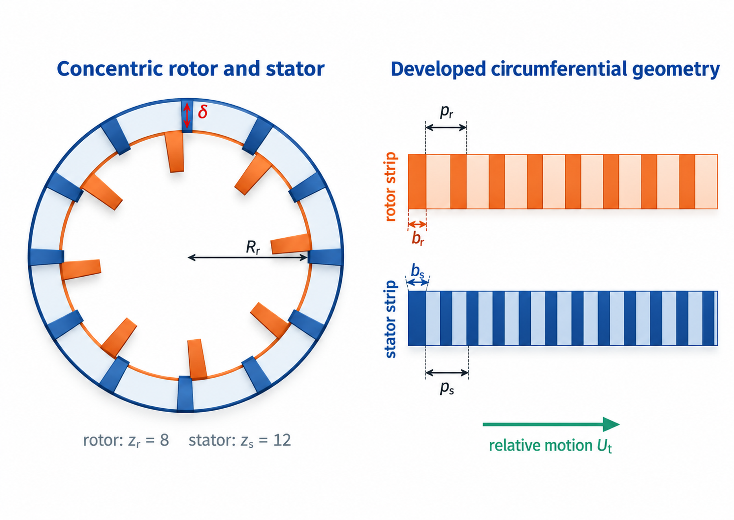
Figure 1.1. Representative cylindrical calculation geometry and developed circumferential patterns. The schematic identifies rotor and stator features, clearance, pitch, opening width and relative motion.
Table 1.1. Minimum input data for an engineering calculation
| Data group | Required quantities | Why they are needed |
|---|---|---|
| Rotor geometry | Outside diameter, active radius, axial height, number of teeth or slots, slot width and depth, number of rows | Determines tip speed, opening area, event frequency, wetted area, and rotational drag |
| Stator geometry | Inside diameter, opening count, opening width and height, open area, edge thickness | Determines restriction, jet velocity, pressure loss, and overlap with the rotor pattern |
| Clearances | Radial gap, axial gap, runout allowance, thermal growth allowance | Controls nominal shear, leakage, friction, contact risk, and local pressure |
| Operating point | Rotor speed, flow rate, inlet and outlet absolute pressure, temperature | Defines kinematics, residence time, hydraulic power, cavitation margin, and heat balance |
| Fluid properties | Density, dynamic viscosity, kinematic viscosity, vapor pressure, speed of sound, heat capacity, surface tension | Required for Reynolds, Womersley, cavitation, bubble, acoustic, and thermal calculations |
| Measured performance | Torque or electrical input, no load power, pressure waveform, flow waveform, vibration and sound | Separates mechanical losses from fluid power and validates the unsteady model |
SI units are used throughout. Rotational frequency is expressed in revolutions per second, whereas shaft speed is expressed in revolutions per minute. The conversion is
The corresponding angular speed is
For active diameter and radius , the peripheral velocity is
Tip speed establishes a useful kinematic scale. Its interpretation requires the gap width, opening area, flow rate, pressure and exposure time because those quantities determine how the available motion is transferred to the liquid.