
Technical publication
Back to publications
Other
Engineering Calculations for Rotor-Stator Mixers
okozyuk.com
Published
Updated
Read complete publication for whole-document Find and printing. Browser Find and native printing on this reader include only loaded content.
10 Engineering calculation procedure
A preliminary engineering calculation should produce a reproducible operating specification and an explicit plan for validating the quantities that remain uncertain. The following sequence connects the preceding relations to equipment selection and commissioning.
-
State the process objective through a measurable particle, droplet, dissolution, reaction or microbial endpoint, together with allowable temperature, pressure, gas entrainment and material wear.
-
Define the control volume for power, flow and pressure measurements, identifying the working head, housing, recirculation circuit or complete vessel as appropriate.
-
Record the active diameters, feature counts, opening dimensions, radial and axial clearances, number of rows and bypass paths.
-
Determine rotational frequency, angular speed and tip speed using Equations (1.1) to (1.3).
-
Evaluate pitch, manufactured slot area and time dependent overlap using Equations (3.1) to (3.6), distinguishing minimum, mean and maximum simultaneous openings.
-
Identify shaft frequency, local feature passage frequency, geometric overlap periodicity and the harmonics relevant to instrumentation and resonance.
-
Estimate passage and gap velocities, nominal residence time and event count using clearly identified flow areas and active volumes.
-
Select a quasi steady or transient passage model from the expected importance of inertia, oscillatory boundary layers and system compliance.
-
Calculate Reynolds, Strouhal, Womersley and Euler numbers, together with flow, pressure and power coefficients, recording the reference scales used in each definition.
-
Evaluate nominal gap shear, viscous stress and laminar Couette torque, and compare their scale with measured or appropriately calibrated power data.
-
Assess cavitation using absolute reference pressure, vapor pressure at the process temperature, a justified velocity scale and a measured or modeled local pressure history.
-
Calculate shaft and hydraulic power, specific energy and the associated thermal load using one consistent boundary and a declared treatment of mechanical losses.
-
Check operating clearance, runout, bearing and shaft loading, seal limits, vibration, erosion and tolerance to particles under the intended operating conditions.
-
Specify the measurements, calibration, sampling bandwidth, uncertainty assessment and product sampling needed to validate the proposed operating range.
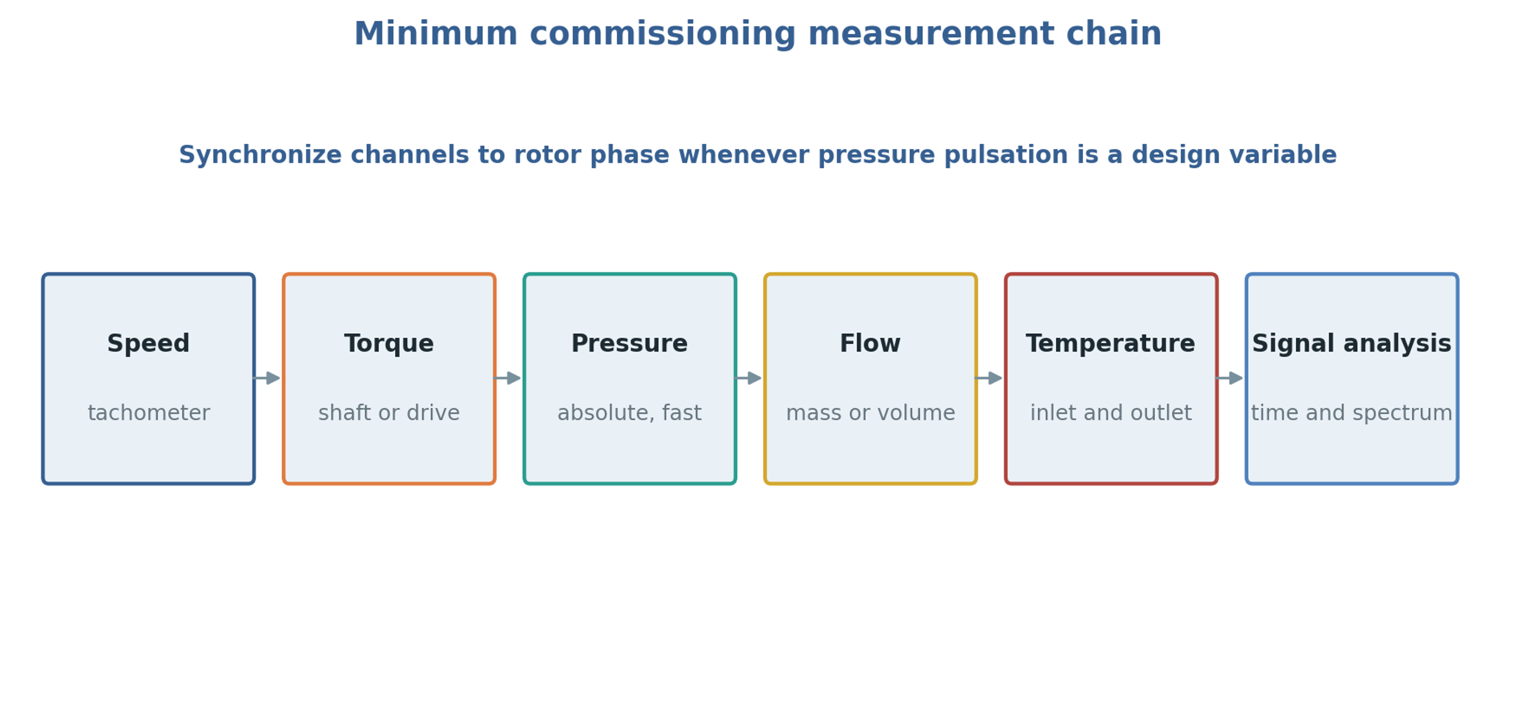
Figure 10.1. Measurement and analysis chain for commissioning. The arrangement represents synchronized acquisition and interpretation of signals rather than a physical sequence of fluid flow.
Table 10.1. Recommended calculation output sheet
| Output | Symbol | Unit | Reported basis |
|---|---|---|---|
| Tip speed | m/s | Active outside diameter | |
| Minimum and mean open area | , | mm² | Specify overlap and leakage area; report discharge coefficient separately |
| Local pulse frequency | Hz | Rotor feature passage at fixed stator location | |
| Integrated overlap symmetry repeat | Hz | Ideal pattern periodicity or numerical area calculation | |
| Nominal gap shear rate | screening value | ||
| Reynolds, Strouhal, Womersley | , , | 1 | Explicit reference length and velocity |
| Cavitation number | 1 | Absolute pressure and local vapor pressure | |
| Shaft power | kW | Measured torque or corrected drive input | |
| Hydraulic power | kW | Mean term; report fluctuation covariance separately | |
| Specific energy | kJ/kg | Net or gross basis stated | |
| Temperature rise | °C | Measured and adiabatic estimate |