
Technical publication
Back to publications
Other
Engineering Calculations for Rotor-Stator Mixers
okozyuk.com
Published
Updated
Read complete publication for whole-document Find and printing. Browser Find and native printing on this reader include only loaded content.
11 Worked screening example
The screening example considers an inline cylindrical stage with the following specified geometry and fluid properties. These inputs define an illustrative Newtonian liquid rather than a complete material specification. In particular, the viscosity is 5 mPa s, so the example should not be interpreted as a pure water calculation at room temperature.
Table 11.1. Specified inputs for the screening example
| Input | Value |
|---|---|
| Rotor outside diameter | 80 mm |
| Shaft speed | 6000 rpm |
| Rotor and stator slots | 8 and 12 |
| Radial clearance | 0.50 mm |
| Stator slot width and active height | 2.0 mm and 8.0 mm |
| Mean volumetric flow | 2.0 L/s |
| Liquid density | 1000 kg/m³ |
| Dynamic viscosity | 5 mPa s |
| Vapor pressure | 3.2 kPa absolute |
| Reference inlet pressure | 200 kPa absolute |
The calculated rotational frequency is , and the angular speed is 628.3 rad/s. Equation (1.3) gives 25.13 m/s for the tip speed. The rotor passage frequency is 800 Hz from Equation (4.1), whereas the ideal circumferential symmetry repeat is Hz from Equation (4.2). The latter is a geometric result and does not establish the dominant pressure frequency.
The total manufactured stator opening area is mm². Dividing the specified flow by this area gives 10.4 m/s under full exposure with contraction neglected. Rotor opening width has not been specified, so this value does not resolve the minimum simultaneous overlap or the actual contracted jet area. Equation (6.2) gives the nominal gap shear rate as , corresponding to approximately 251 Pa for the specified Newtonian viscosity.
Using and the 0.50 mm gap gives a Reynolds number of approximately 2510. At 800 Hz the Womersley number based on the same length is approximately 15.9, indicating that oscillatory inertia and phase lag warrant consideration. Using as the velocity reference in Equation (8.5) gives a cavitation number near 0.62. Cavitation inception cannot be established from this number alone because the local pressure coefficient, pressure fluctuation amplitude and nuclei population are unspecified.
The specified density and viscosity give a kinematic viscosity of 5.0 × 10⁻⁶ m²/s. Equation (5.13) then gives an oscillatory viscous penetration depth of approximately 44.6 µm at 800 Hz, substantially smaller than the 500 µm radial gap. This comparison supports retaining oscillatory inertia in a transient passage calculation. It does not establish a fully turbulent gap state, whose stability and throughflow must be examined separately.
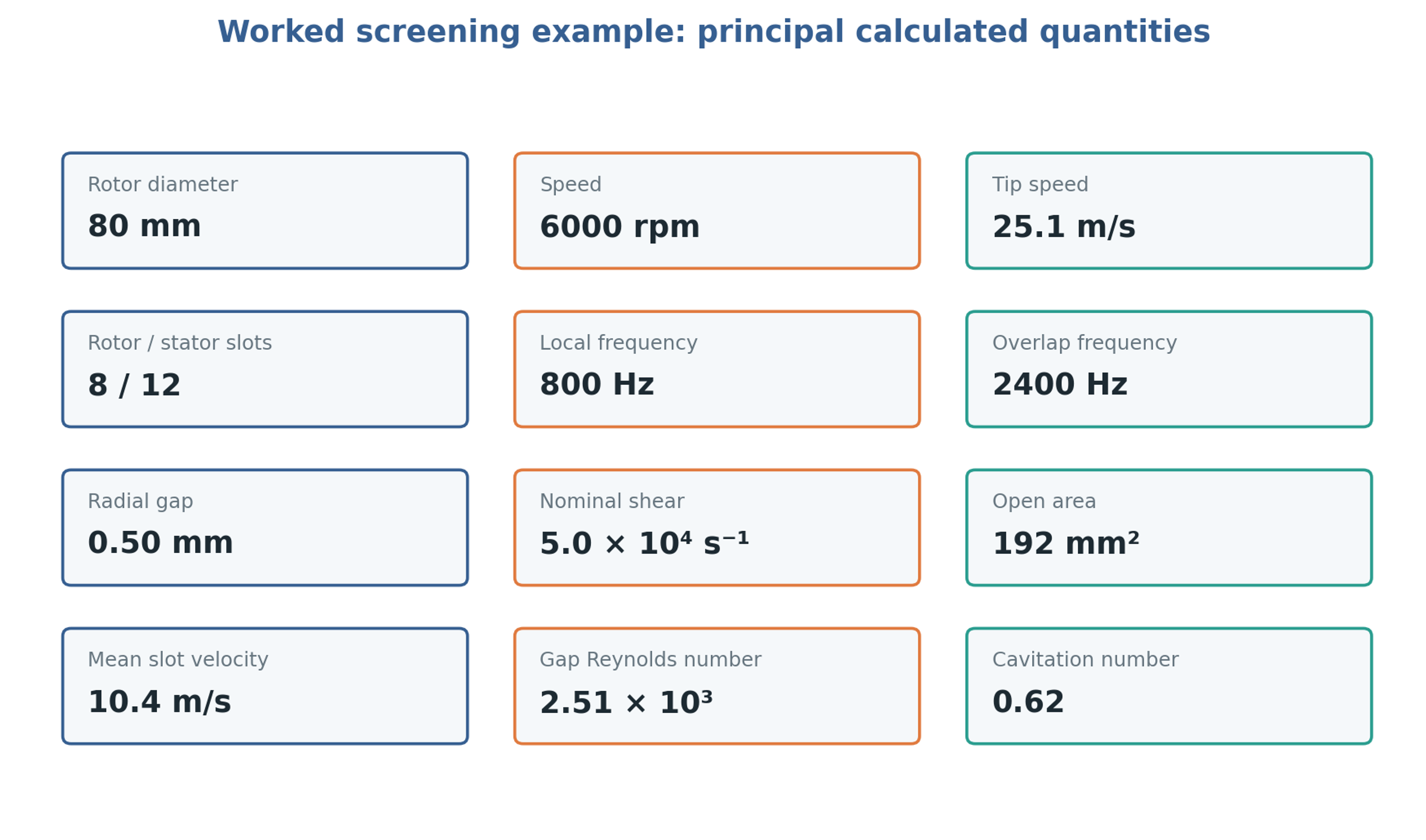
Figure 11.1. Specified and calculated quantities for the screening example. The area is the total geometric stator area and the higher frequency is the ideal overlap symmetry repeat.
Table 11.2. Worked example calculation summary
| Quantity | Calculation | Result |
|---|---|---|
| Rotational frequency | 100 | |
| Tip speed | 25.13 m/s | |
| Local passage frequency | 800 Hz | |
| Overlap symmetry repeat frequency | 2400 Hz | |
| Total geometric stator area | 192 mm² | |
| Nominal slot velocity at full exposure | 10.4 m/s | |
| Nominal gap shear | ||
| Nominal shear stress | 251 Pa | |
| Gap Reynolds number | 2510 | |
| Cavitation number | 0.62 | |
| Womersley number | Gap based oscillatory inertia measure | 15.9 |
| Viscous penetration depth | At the local passage frequency of 800 Hz | 44.6 µm |
The given inputs do not determine shaft power. A measured torque or a validated power correlation for the actual head is required before specific energy and heat generation can be calculated. Initial characterization should establish mechanical losses with an appropriate safe baseline and then measure the liquid loaded torque over speed and flow. Absolute pressure measurements at the inlet and near the stator discharge are needed to assess the local pressure margin. Representative fluid tests should follow the hydraulic baseline because viscosity and gas content can alter both load and cavitation behavior.