
Technical publication
Back to publications
Other
Emulsification and Homogenization in Rotor-Stator Mixers
okozyuk.com
Published
Read complete publication for whole-document Find and printing. Browser Find and native printing on this reader include only loaded content.
8 Effects of operating variables
Operating variables affect several mechanisms simultaneously. A change in speed, flow, phase fraction, or temperature can alter the imposed stress, the time available for deformation, and the rate at which new interface is stabilized. The following discussion interprets these coupled effects and identifies the measurements needed to determine which mechanism controls the observed product [1, 3, 6, 10].
8.1 Rotor speed and tip speed
Rotor speed is a principal operating variable because it changes both the intensity and the frequency of hydrodynamic exposure. Increasing speed simultaneously changes tip velocity, pumping, blade passage frequency, turbulence, pressure pulsation, and power consumption. Tip speed provides a useful initial scale up parameter because it characterizes a local velocity scale. However, equal tip speeds do not imply equal residence times, velocities through the stator openings, Reynolds numbers, or power densities. Hall obtained useful translation of mean droplet size among the inline mixers investigated by combining comparable tip speed with comparable residence time; stator open area also had a substantial effect [3].
The dependence of mechanical power on speed and rotor diameter is commonly expressed through a dimensionless power number:
Here, is the power number. Its value depends on the geometry, Reynolds number, imposed flow, and fluid rheology; it should be established for the operating regime under consideration.
At fixed geometry and approximately constant power number, the fully turbulent scaling implies that power increases with the cube of rotor speed. A relatively small speed increase can therefore impose a substantial additional motor and cooling load. The operating speed should be selected together with exposure time so that the required droplet distribution and stability are obtained within the mechanical and thermal limits. The minimum speed is not necessarily the minimum energy condition, because a higher speed may shorten the processing time.
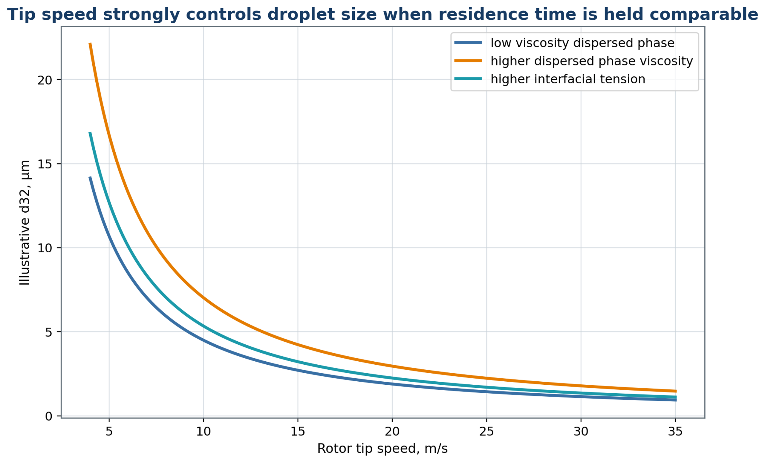
Figure 8.1. Illustrative dependence of droplet diameter on rotor tip speed, with schematic changes associated with dispersed phase viscosity and interfacial tension [2, 3, 4]. The curves are not universal equipment correlations or comparative manufacturer data.
8.2 Flow rate, residence time, and pass number
Flow rate determines how rapidly material enters and leaves the active region and therefore couples throughput to exposure. In an inline mixer, a higher flow rate generally reduces mean residence time while increasing the velocity through the stator openings. These effects compete, and the observed mean droplet diameter can increase, decrease, or remain approximately unchanged. Flow rate should consequently be evaluated together with rotor speed, open area, and the pressures upstream and downstream of the head [1, 3, 10].
Direct flow measurements support this coupled interpretation. Espinoza and coauthors used particle image velocimetry in a transparent inline Silverson head and observed that the dominant flow could shift between radial and tangential motion. External flow promoted radial transport, while increasing rotor speed or outlet backpressure favored tangential motion under the conditions studied. These findings indicate that the surrounding pump and pipework can change the exposure history even at a fixed head geometry [33].
For a prescribed volumetric flow, a characteristic average velocity through the open passages is
where denotes the total instantaneous open area. This estimate assumes that the stated flow passes through that area; local velocities can differ because of nonuniform flow splitting and time dependent rotor obstruction.
The corresponding port Reynolds number, based on the hydraulic diameter , is
Repeated processing usually removes the coarse population most rapidly during the early passes, after which the rate of refinement decreases. Further passes continue to increase energy input and temperature and may expose sensitive ingredients to oxidation or structural damage. The required pass number should be determined from the evolution of , , distribution span, and stability with cumulative specific energy. Processing time alone does not identify the exposure received by each fluid element.
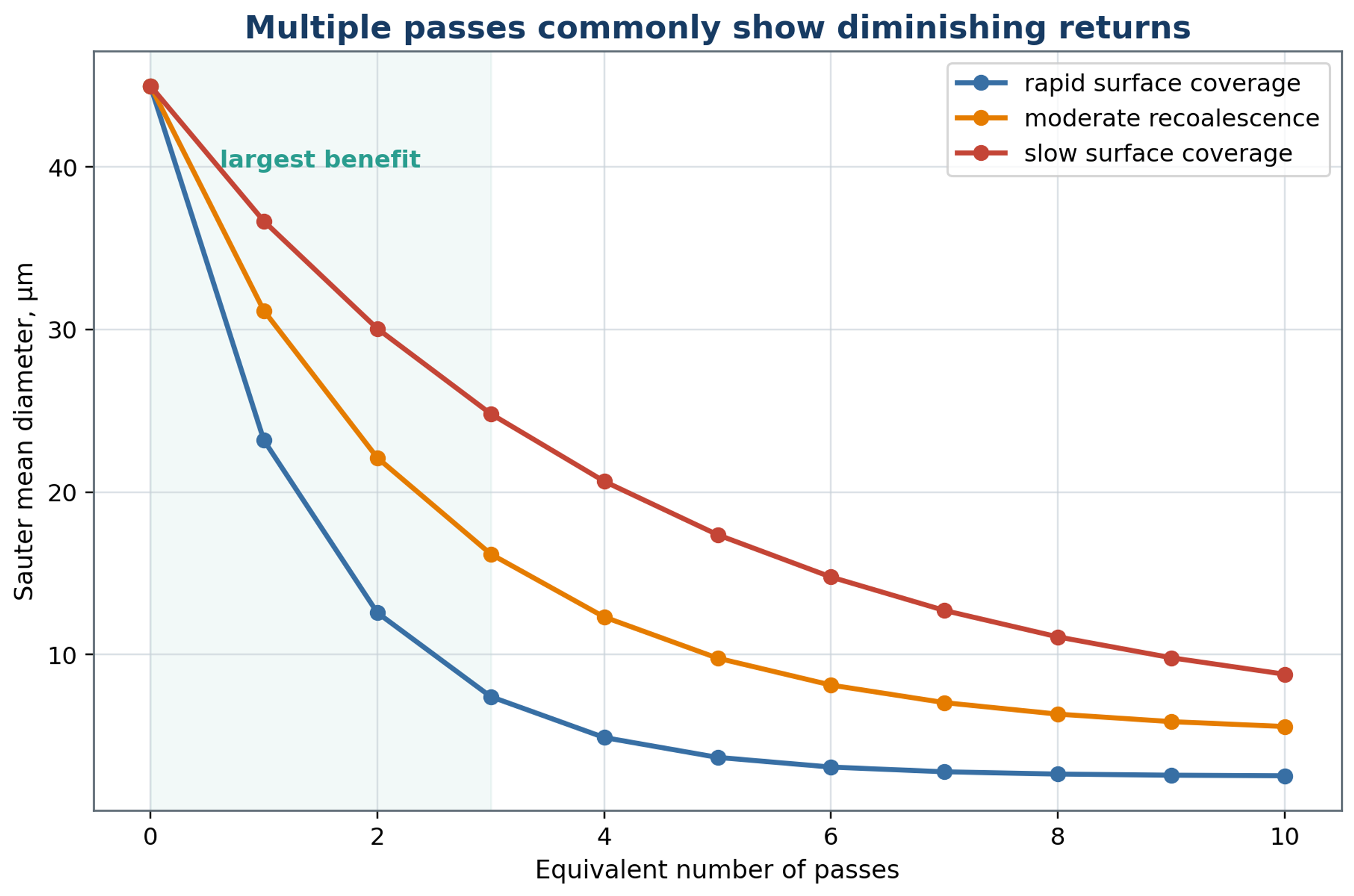
Figure 8.2. Illustrative approach to a limiting droplet size with repeated equivalent passes. Differences in adsorption and recoalescence can change both the limiting diameter and the rate of approach. The curves are conceptual examples.
8.3 Phase viscosities and viscosity ratio
The viscosities of the two phases govern different aspects of emulsification. Dispersed phase viscosity resists internal motion, neck thinning, and fragment separation, whereas continuous phase viscosity controls the surrounding viscous stress, turbulent damping, and transport through the mixer. At otherwise comparable conditions, a larger viscosity ratio commonly increases the resistance to breakup or changes the breakup morphology. An increase in continuous phase viscosity can facilitate viscous deformation while simultaneously reducing turbulent fluctuations and pumping. The dominant mechanism must therefore be identified before a viscosity trend is generalized [3, 4, 6, 27].
Both viscosities should be evaluated at the actual processing temperature. For a non-Newtonian formulation, a single viscosity value is insufficient: the rheological measurements should cover the conditions relevant to the feed pump, bulk circulation, and active head. Temperature or composition changes during a batch can move the process between different flow and breakup regimes.
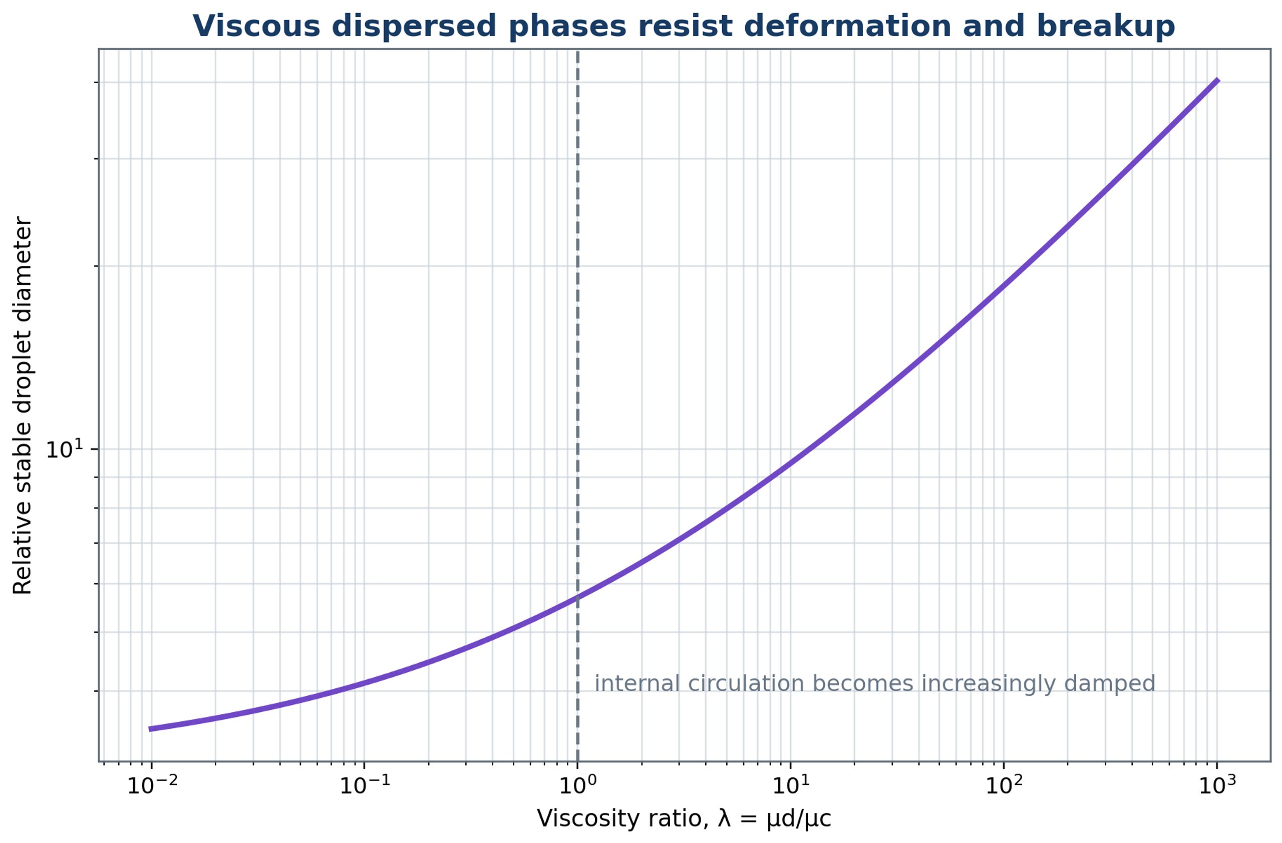
Figure 8.3. Schematic influence of dispersed to continuous phase viscosity ratio on resistance to deformation and breakup. The plotted trend is qualitative; a quantitative response also depends on the flow regime, interfacial mobility, and stress duration.
8.4 Dispersed phase fraction
The dispersed phase fraction connects formulation concentration to the amount of interface, the frequency of droplet encounters, and the bulk rheology. Increasing increases the interfacial area required at a specified diameter and generally increases the opportunity for collisions. It can also increase apparent viscosity and reduce the continuous phase volume available to transport emulsifier. In concentrated systems, interactions among droplets modify the local flow, so breakup correlations established under dilute conditions may no longer apply [3, 6].
The mean separation between neighboring droplet surfaces provides a conceptual measure of crowding. In process development, rheology, conductivity, and microscopy often provide more accessible evidence of structural change or an approaching phase inversion. Trials should include the minimum, nominal, and maximum intended phase fractions. A correlation calibrated at a single concentration should not be transferred to a substantially different concentration without verification.
8.5 Temperature, gas, and cavitation
Temperature and gas content affect both the liquid properties and the hydrodynamic conditions in the head. Heating commonly lowers phase viscosity and may lower interfacial tension, but the magnitude and direction of these changes depend on the formulation. Higher temperature also increases vapor pressure and can accelerate oxidation, chemical reactions, protein denaturation, or degradation of active ingredients. The recorded thermal history should include inlet and outlet temperatures, the maximum temperature in a recirculation loop, and the duration of exposure.
Air entrainment changes the apparent density, measured particle distribution, power demand, and pressure response. In batch operation, a surface vortex can draw gas into an inadequately submerged head; in inline operation, suction leaks can introduce gas into the process stream. The resulting bubbles can generate foam and modify cavitation collapse. Adequate immersion, a submerged return, and monitored suction conditions improve reproducibility. Deaeration can be useful when compatible with the formulation, although vacuum treatment may remove volatile constituents.
Table 8.1. Operating variables and diagnostic responses.
| Variable increased | Expected useful response | Possible adverse response | Essential diagnostic |
|---|---|---|---|
| Rotor speed | Higher stress and faster passage frequency | Cubic power rise, heat, air ingestion, wear | Torque, power, temperature, DSD |
| Flow rate | Higher capacity and port velocity | Shorter residence, pressure loss, bypass | Flow, pressure, residence distribution |
| Processing time or passes | Lower mean and coarse tail initially | Diminishing returns, heat, oxidation | DSD by pass and cumulative energy |
| Dispersed phase fraction | Higher production concentration | Collision, viscosity, inversion | Rheology, conductivity, DSD |
| Emulsifier concentration | Lower tension and faster coverage | Cost, taste, micelles, phase behavior | Dynamic tension and storage test |
| Temperature | Lower viscosity | Degradation, vapor, lower collapse intensity | Full temperature history |
| Backpressure | Alters recovery and cavitation | Excess pressure load or suppressed inception | Fast pressure and acoustic signal |
| Dissolved gas | More nuclei | Foam and collapse cushioning | Dissolved gas and void fraction |