
Technical publication
Back to publications
Other
Emulsification and Homogenization in Rotor-Stator Mixers
okozyuk.com
Published
Read complete publication for whole-document Find and printing. Browser Find and native printing on this reader include only loaded content.
9 Effects of rotor and stator geometry
Rotor and stator geometry transforms the motor input into spatially distributed shear, extension, jets, and pressure fluctuations. This section considers the dimensions that should be recorded when a process is compared or transferred: clearance, teeth, openings, stage arrangement, and the condition of worn parts. The geometric variables must be considered together with flow rate because an opening that raises local velocity at imposed flow can also restrict circulation [1, 3].
9.1 Radial clearance and tooth geometry
The clearance and the shape of the working elements determine where fluid accelerates and where large velocity gradients arise. Reducing radial clearance increases the nominal gap shear rate at a fixed tip speed, but also increases sensitivity to shaft deflection, thermal expansion, particle blockage, and manufacturing tolerances. Designs that use a controlled liquid film or hydrodynamic support to maintain a small operating gap have been described in patent literature [22]. The practical clearance must be selected from both the required hydrodynamic action and the mechanical conditions, including balance, bearing support, solids content, and allowable wear.
Rotor geometries include straight or swept teeth, grooves, slots, perforations, and several concentric rows. Stators may contain round openings, axial or radial slots, screens, concentric rings, or serrated surfaces. These features influence open area, jet direction, contraction, pressure recovery, pumping, and the sequence of shear and pulsation events. A geometric description should therefore include dimensions and flow paths rather than rely only on commercial designations such as coarse or fine [1, 3, 13, 14, 18, 21, 22].
Manufacturer documentation illustrates the range of practical configurations without establishing equivalent product performance. Silverson describes interchangeable general purpose heads, slotted heads, and emulsor screens, together with multistage combinations of inner and outer stators. This modularity permits passage geometry to be matched to liquid emulsification or to feeds containing larger or fibrous material. The appropriate combination must still be selected from trials with the intended formulation [11].
Patent disclosures provide additional examples of geometry rather than independent performance validation. Paterson describes rotor and stator arrangements for mixers and emulsifiers, while Ekstrom and coauthors describe an inline housing containing successive rotor and stator elements [34, 35]. Other disclosures address performance estimation and scale up, or outlet configurations that influence the discharge from a dispersion machine [36, 37]. These documents should be interpreted together with the measured hydrodynamics of the particular device.
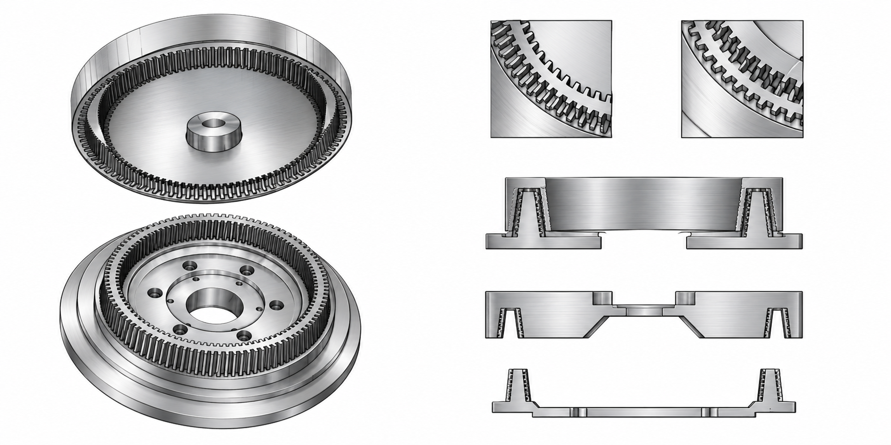
Figure 9.1. Grooved rotor and stator components, groove details, and sectional arrangements. The views are not dimensional manufacturing drawings.
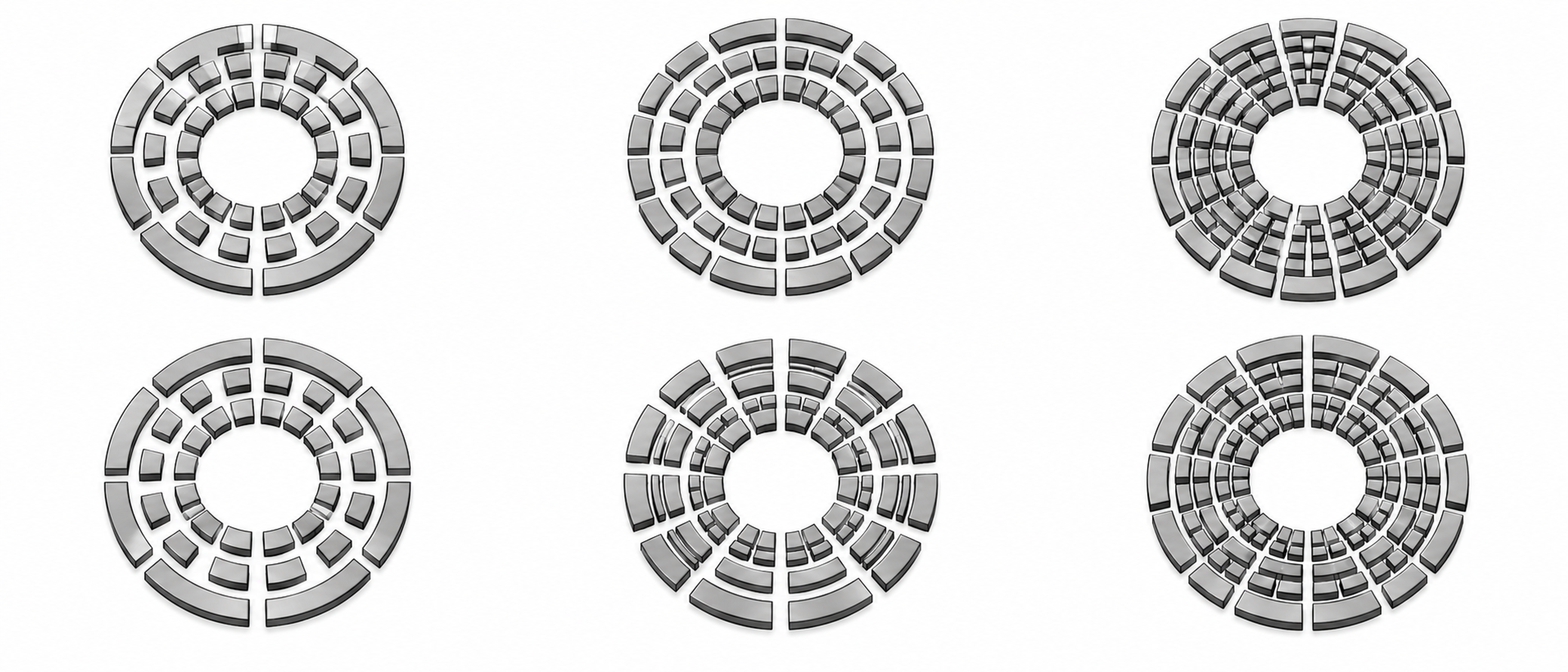
Figure 9.2. Six concentric ring arrangements. Alternating segmented passages permit periodic changes in opening area. The patterns illustrate geometric concepts and are not dimensional manufacturing drawings.
9.2 Stator open area and slot width
The stator opening pattern establishes the hydraulic connection between the rotating region and the surrounding or downstream liquid. A useful geometric descriptor is the fraction of the reference stator area that is open to flow:
Here, is the reference stator surface area. The selected reference surface and the treatment of openings temporarily blocked by the rotor should be stated so that reported open area ratios are comparable.
At an imposed flow rate, reducing open area raises the average velocity through the remaining openings and can increase pressure loss. In a self-pumping system, however, the flow rate also changes, so the response cannot be inferred from area alone. Fine openings can modify deformation and residence histories and may reduce the coarse fraction, while increasing sensitivity to fibers, crystals, agglomerates, and fouling. Hall identified open area as a particularly influential geometric variable for power consumption and emulsification in the inline mixers studied [3].
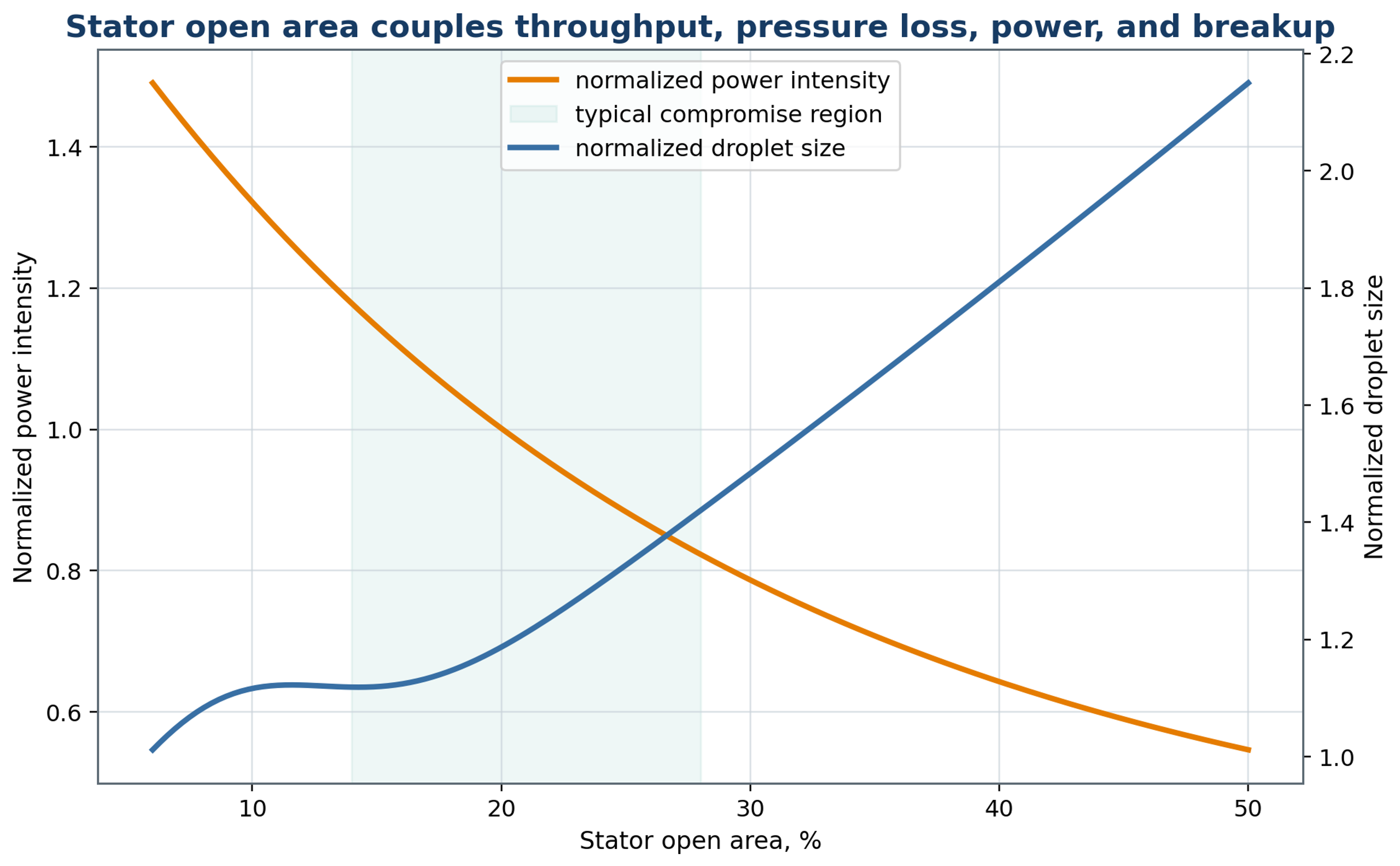
Figure 9.3. Conceptual relationship among stator open area, normalized power intensity, and droplet size. The shaded interval is an illustrative compromise region, not a validated universal design range.
9.3 Stage sequence and feed orientation
A sequence of processing stages permits the geometry to be adapted to the changing dispersion. A relatively coarse first stage distributes the secondary phase and reduces large domains before the material enters finer stages. This arrangement can improve operating robustness when the feed contains a broad droplet distribution or agglomerates. The orientation of successive openings also affects jet direction and the exposure history. Adequate passage area and pressure control are required throughout the sequence; simply adding stages does not establish that additional energy will improve the product.
IKA specifies three successive rotor stator generators for its DISPAX REACTOR DR 2000, with standard progression from coarse to medium to fine elements. The equipment can be integrated into a recirculating batch arrangement or supplied continuously. This documented configuration provides a practical example of staged processing, while the number of passes and resulting distribution remain dependent on the product and operating conditions [12].
The feed position determines whether the secondary liquid first encounters the rotor inlet, the annular region, or an upstream premixing zone. Injection close to an active region can shorten the interval available for bulk separation. However, a concentrated feed can also produce local phase inversion or encounter insufficient emulsifier. Computational flow analysis, tracer measurements, and conductivity tests can be used to investigate bypass and unequal feed distribution before product trials.
9.4 Wear and geometric drift
Wear gradually changes the geometry on which a process correlation depends. Edge rounding, clearance growth, erosion, and stator deformation alter local velocities and stress distributions. The nominal blade passage frequency remains determined by speed and element count, although damaged or missing features can alter the pressure spectrum. Average power can remain similar while the droplet distribution changes. Dimensional inspections, vibration measurements, and baseline flow and torque tests should therefore accompany routine maintenance. Replaceable generators are useful when abrasive ingredients or cavitation cause measurable wear.
Table 9.1. Geometry variables and design consequences.
| Geometry variable | Primary hydrodynamic effect | Product consequence | Mechanical consequence |
|---|---|---|---|
| Rotor diameter | Changes tip speed and power scale | Changes breakup intensity | Changes torque and shaft load |
| Radial gap | Controls local shear and leakage | Can affect fine size and uniformity | Tolerance, heating, contact risk |
| Number of rotor teeth | Changes passage frequency | Changes pulse count per residence | Balance and fabrication complexity |
| Stator open area | Controls port velocity and pressure loss | Strong effect on DSD and capacity | Motor load and blockage risk |
| Slot width | Sets contraction scale and solids tolerance | Influences coarse tail | Fouling and cleaning sensitivity |
| Number of stages | Adds sequential exposure | Can narrow DSD | Adds heat, pressure loss, parts |
| Groove orientation | Controls collision and circulation | Changes deformation history | Wear pattern and manufacturability |