
Technical publication
Back to publications
Other
Emulsification and Homogenization in Rotor-Stator Mixers
okozyuk.com
Published
Read complete publication for whole-document Find and printing. Browser Find and native printing on this reader include only loaded content.
4 Hydrodynamic exposure in rotor-stator mixers
The relationship between mixer settings and droplet breakup depends on the stresses experienced by individual droplets, rather than on shaft speed alone. A useful hydrodynamic description distinguishes velocity scales, deformation rates, flow regimes, periodic forcing, and local pressure conditions. The quantities introduced below provide a framework for comparing devices while making explicit the approximations involved in reducing a complex, unsteady flow to a small set of operating variables.
4.1 Active zones and stress history
The hydrodynamic exposure of a droplet comprises the complete sequence of stresses encountered along its trajectory. The nominal radial clearance is only one part of that sequence. Axial entry, centrifugal acceleration, rotor passages, gap flow, periodic stator opening, jet formation, impingement, pressure recovery, and recirculation can each contribute to deformation. The relative contribution depends on head geometry, flow rate, viscosity, and position within the device. Mean velocities and fluctuating components therefore need to be interpreted over several spatial and temporal scales when relating operating conditions to breakup [1, 3, 8, 10, 13, 14, 24, 25, 26, 27].
Direct observations provide evidence that the principal breakup region can extend beyond the nominal rotor clearance. Ashar and coauthors used a mixer with optical access and found that breakup occurred mainly downstream of the stator and within the emerging jets. Their measurements also showed that parent droplet size affected the duration and distribution of interactions with vortical structures [28]. These observations support the use of a trajectory based stress history and caution against assigning all fragmentation to the narrow gap. The reported locations apply to the investigated device and operating conditions.
Rotor tip speed provides a convenient measure of the velocity scale associated with rotation:
where is rotor diameter and is rotational frequency in s⁻¹. The speed specified in revolutions per minute must be divided by 60 before substitution.
A comparison based on tip speed and radial clearance gives the nominal shear rate
This ratio provides a geometric estimate, rather than a complete description of the local strain field. Blade shape, slip, leakage, turbulence, and changing rotor and stator overlap produce substantial spatial and temporal variation. The nominal value is therefore useful for comparing geometries but is insufficient as the sole basis for predicting breakup or transferring a process between scales.
The relative importance of inertia and viscosity at the overall rotor scale is expressed by the rotor Reynolds number:
where and denote continuous phase density and dynamic viscosity, respectively.
Transport within the smaller clearance can be characterized separately by a gap Reynolds number:
The rotor and gap Reynolds numbers refer to different characteristic lengths and velocities and should not be used interchangeably. The former describes the overall rotating scale; the latter concerns motion over the clearance. For non-Newtonian liquids, any apparent viscosity used in these definitions should correspond to a justified shear rate and process temperature. A reported Reynolds number should identify the selected viscosity model and characteristic scales.
The flow generated by a head can change when stator openings are modified, even if rotor speed is held constant. Particle image velocimetry measurements by Mortensen and coauthors related differences in slot width to flow number, velocity profile shape, and the fraction of fluid returning through a slot. Within the investigated geometries, the flow number decreased as slot width increased [29]. The result shows that an opening dimension cannot be interpreted independently of the resulting circulation and backflow. Its direction and magnitude should be verified for the actual rotor and stator combination.
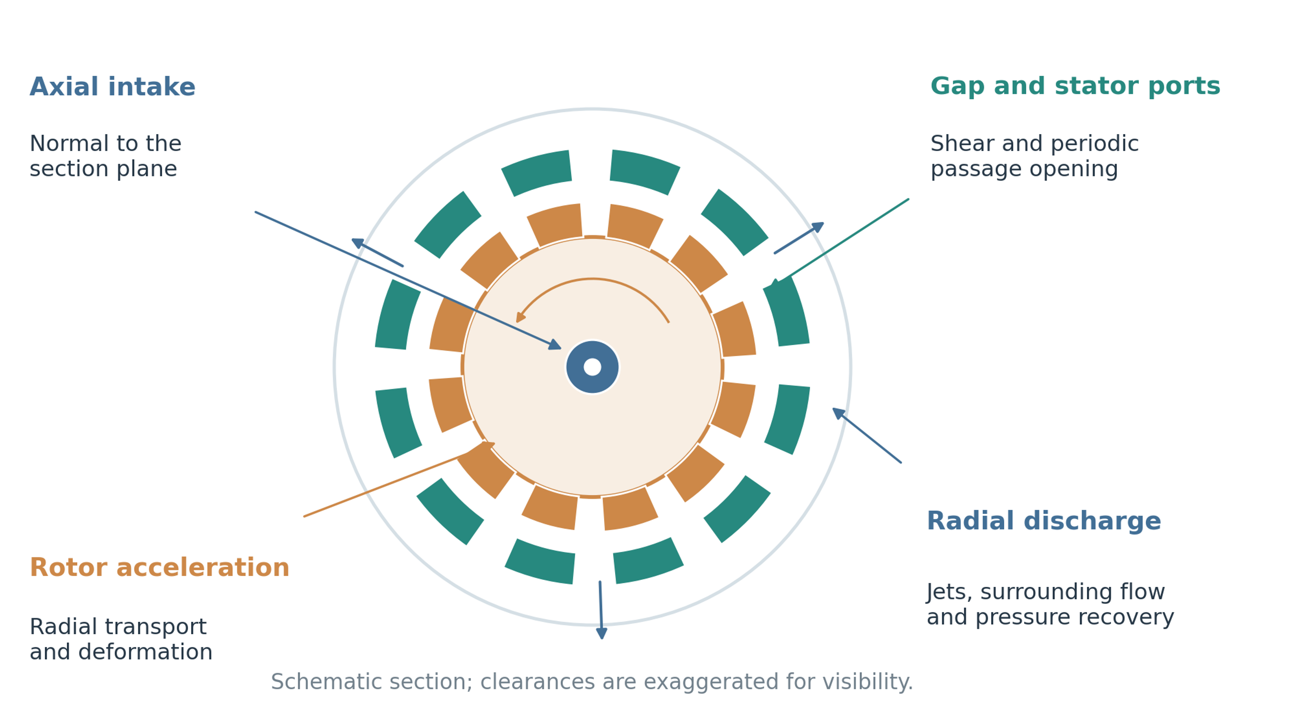
Figure 4.1. Principal hydrodynamic regions in a rotor-stator head. Axial intake, rotor acceleration, deformation in clearances and openings, radial discharge, and downstream pressure recovery contribute different portions of the stress history. The drawing is schematic.
4.2 Pulsation frequency and periodic exposure
Periodic passage of teeth or ports introduces characteristic frequencies into the local velocity and pressure fields. These frequencies help describe repeated deformation events and can guide the interpretation of pressure, vibration, and acoustic measurements. For equivalent rotor teeth or ports and rotational frequency , the blade or port passage frequency observed at a fixed location is approximated by
When a specified rotor and stator pattern produces an effective count of opening events per rotor revolution, the corresponding primary overlap frequency is
Rotary pulsation devices are designed to exploit this periodic change in passage area. Their pressure and velocity spectra may contain blade and opening frequencies, harmonics, beat frequencies, and responses associated with structural motion. Superimposed axial or piston motion introduces further frequencies [13, 14, 16, 17, 18]. A larger pressure amplitude does not by itself establish resonance of the droplets. Evidence of droplet resonance requires comparison of the forcing spectrum with the droplet response under the actual viscosity, interfacial tension, and confinement conditions. Mechanical resonance must be considered separately because it can increase vibration, fatigue, bearing loads, and demands on seals.
4.3 Turbulence, pressure pulsation, and cavitation
Turbulence, pressure pulsation, and cavitation introduce different forms of unsteadiness and should be distinguished when interpreting mixer performance. Turbulence generates velocity fluctuations over a range of scales. Periodic changes in passage area generate pressure and velocity oscillations that can influence deformation when they create relative motion or pressure gradients around droplets. Cavitation occurs when local pressure and the available nuclei permit rapid cavity growth. Subsequent collapse can generate localized jets, pressure waves, and large velocity gradients. Its contribution is conditional: extensive vapor regions or noncondensable gas can reduce collapse intensity, alter pumping, promote foaming, or accelerate erosion. Cavitation therefore cannot be assumed to improve emulsification in every operating regime [13, 14, 15, 18, 30].
A conventional measure of the pressure margin relative to a selected dynamic pressure scale is the cavitation number:
where is the specified reference pressure, is vapor pressure at the process temperature, and is the selected characteristic velocity.
A cavitation number is meaningful only with its pressure location, velocity definition, temperature, and liquid state specified. It is particularly useful for comparisons made with a consistent device and measurement arrangement. If cavitation is invoked as a breakup mechanism, the interpretation should also consider pressure measurements, visual or acoustic observations, erosion evidence, and product response. Gas release and vapor cavitation should be distinguished when the available measurements permit.
Table 4.1. Hydrodynamic mechanisms and their expected effects.
| Mechanism | Characteristic source | Useful action | Main limitation or risk |
|---|---|---|---|
| Mean viscous shear | Rotor stator clearance and wall layers | Deformation of small droplets and viscous systems | Local rate may be overestimated by simple gap calculation |
| Extensional flow | Intake, contractions, slot entry, jet formation | Efficient elongation and ligament formation | Strongly geometry dependent |
| Turbulent inertial stress | Large energetic eddies and jets | Breakup of droplets larger than the smallest eddies | Stochastic exposure produces broad outcomes |
| Turbulent viscous stress | Small dissipative eddies | Important when droplets are below the Kolmogorov scale | High viscosity and heating may dominate |
| Pressure pulsation | Periodic overlap of rotor and stator passages | Repeated acceleration and deformation | Vibration, fatigue, and resonance risk |
| Cavitation collapse | Local pressure depression followed by recovery | Local pressure waves and microjets | Gas cushioning, erosion, foaming, and chemical effects |
| Impingement and collision | Jet collision and groove interaction | Additional deformation and redistribution | May raise coalescence when interface is poorly stabilized |