
Technical publication
Back to publications
Other
Emulsification and Homogenization in Rotor-Stator Mixers
okozyuk.com
Published
Read complete publication for whole-document Find and printing. Browser Find and native printing on this reader include only loaded content.
3 Rotor-stator process architectures
Process architecture governs how liquid reaches the high intensity region, how often it returns, and how heat and composition are controlled between encounters. An immersed batch head, a single pass inline unit, and a recirculating system can use related rotor and stator features while producing different distributions of exposure. Architecture must therefore be considered together with formulation and local stress when selecting a process or interpreting scale up results.
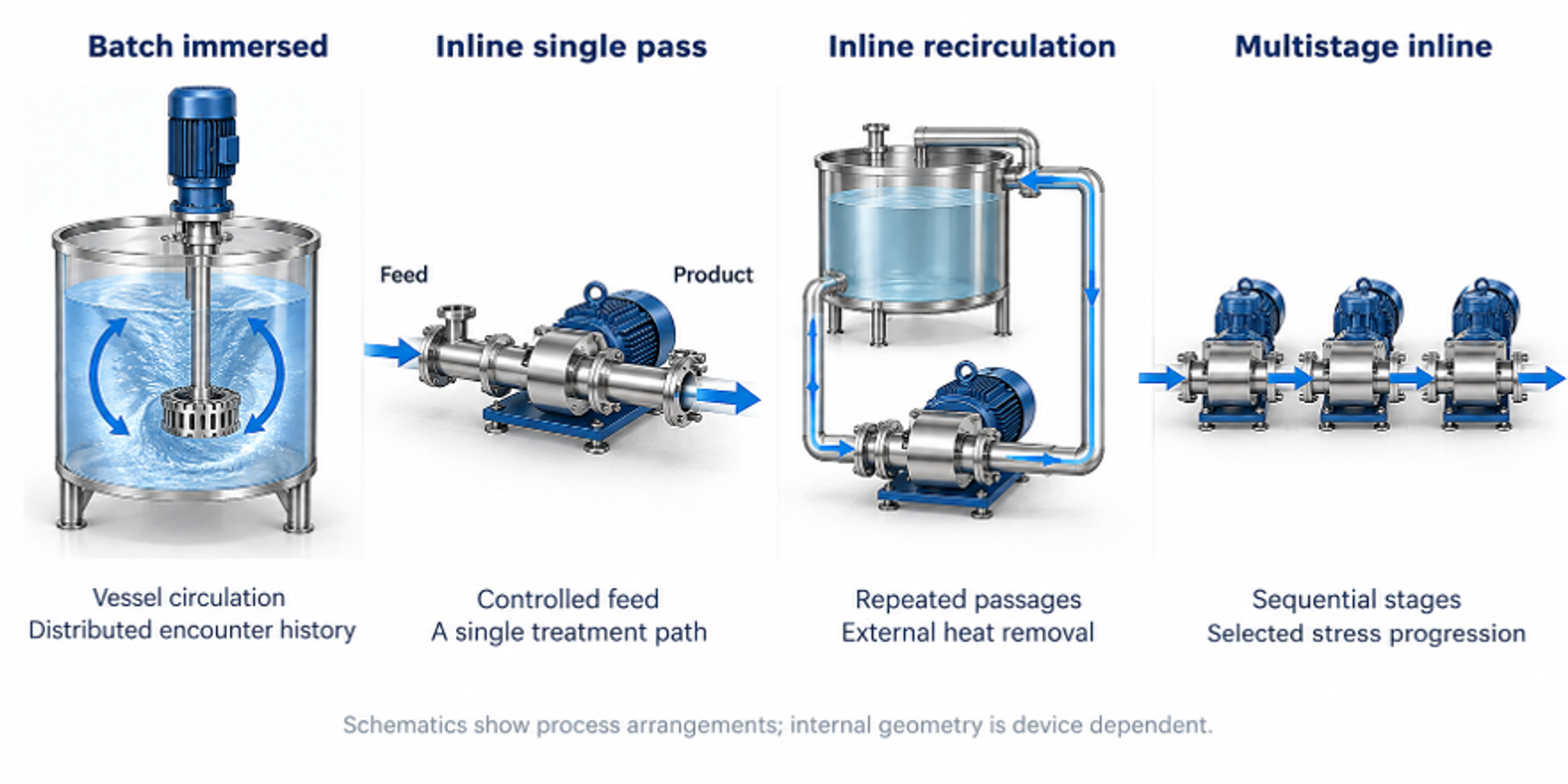
Figure 3.1. Principal process configurations: immersed batch mixing, inline single pass treatment, inline recirculation, and multistage inline processing. The drawings distinguish the flow paths and do not imply equal residence distributions.
3.1 Batch immersed mixers
An immersed batch mixer combines a compact region of intense deformation with circulation through a substantially larger vessel. Liquid is commonly drawn toward the center of the head, accelerated by the rotor, and discharged through stator slots or holes. Residence within the active region may be of the order of milliseconds, whereas total batch treatment is often much longer. Performance therefore depends on the repeated exchange of liquid between the vessel and mixing head. High local stress does not ensure uniform treatment when part of the vessel inventory circulates poorly or rarely reaches the active region [1, 2].
The circulation pattern depends on head elevation, vessel diameter, liquid depth, baffles, viscosity, free surface behavior, and the location of liquid addition. Adequate submergence reduces air ingestion, while clearance from the vessel wall and bottom supports bulk circulation. As apparent viscosity increases, pumping by the rotor stator head can become insufficient even when deformation remains intense near the rotor. Auxiliary anchors, sweeps, or propellers may then supply bulk transport. In such arrangements, the functions of vessel circulation and local dispersive mixing are assigned to different agitators.
For a batch treated at an approximately constant head circulation rate , an idealized mean number of encounters with the head can be estimated from the batch volume :
where t is the elapsed processing time. The result represents a mean exposure count, not an identical number of passages for every fluid element.
Actual encounter histories have a distribution because some fluid elements return rapidly to the head while others remain in regions of weaker circulation. The calculation is consequently a preliminary estimate. Tracer measurements, validated flow simulations, and sampling at several vessel locations can be used to assess departures from ideal circulation. These checks are particularly relevant when the coarse fraction determines acceptance or when scale up changes the vessel proportions, head position, or product viscosity.
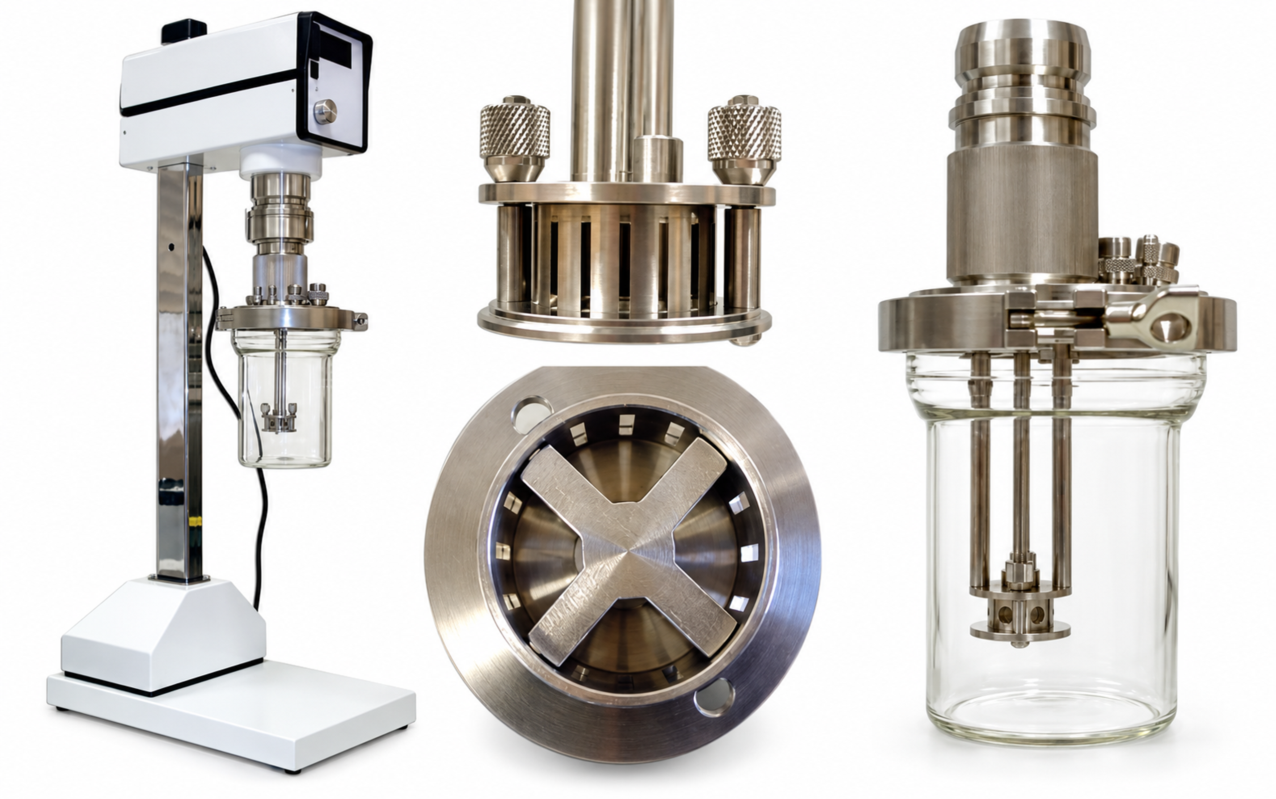
Figure 3.2. Laboratory batch mixer, workhead, underside of the rotor, and vessel arrangement. The views explain the apparatus configuration and are not dimensional engineering drawings.
3.2 Inline single pass and recirculating systems
Inline processing confines the active mixing stages within a housing and links the exposure history to a controlled feed stream. Compared with an immersed batch head, the liquid follows a more defined sequence of acceleration, deformation, and discharge, although the internal residence time remains distributed. Such arrangements permit continuous production, metered addition, and integration with heat exchangers, deaeration systems, reactors, and filling operations. The choice between a single pass and recirculation depends on the required distribution, available stabilization time, thermal limits, and the ability to maintain uniform flow through the head [1, 3, 11, 12].
For an active liquid volume and a steady volumetric flow rate , the nominal mean residence time is
In a recirculation system, total throughput divided by the liquid inventory gives the mean number of equivalent passages:
where is the recirculation flow rate and is the combined liquid inventory represented by the model.
For a perfectly mixed inventory, negligible bypass, and approximately constant circulation rate, the fraction that has not yet entered the device after equivalent passes is
After one equivalent pass, the ideal mixed model predicts that approximately 36.8% of the inventory remains untreated, while some material has already passed through the device more than once. Equivalent pass number therefore measures accumulated throughput rather than uniform treatment. A properly distributed single pass system can provide a narrower exposure history, but this advantage depends on the absence of substantial bypass and unequal flow among passages.
Table 3.1. Selection of process architecture.
| Requirement | Batch immersed | Inline single pass | Inline recirculation | Multistage inline |
|---|---|---|---|---|
| Flexible formulation changes | Excellent | Moderate | Good | Moderate |
| Defined residence history | Low | High | Moderate | High |
| High viscosity handling | Good with auxiliary sweep | Device dependent | Good with suitable pump | Device dependent |
| Heat removal | Vessel jacket or coil | External exchanger | Excellent with loop exchanger | Interstage cooling possible |
| Addition of powders or secondary liquid | Simple but air risk | Controlled injection | Controlled injection and repeated mixing | Stage specific injection possible |
| Exposure uniformity | Depends on tank circulation | Good when manifolding is uniform | Distributed pass count | Good when stages are hydraulically balanced |
| Cleaning and containment | Open or closed vessel | Closed sanitary line | Closed but larger holdup | Closed and compact |
3.3 Single stage and multistage heads
The number and sequence of rotor stator stages determine how deformation is distributed along the flow path. A single stage provides one principal interaction zone, whereas a multistage head places several zones in series. The stages may differ in opening size, tooth geometry, or clearance. A relatively coarse first stage can produce a more uniform and readily transported premix before subsequent stages impose additional deformation. This sequence can reduce intermittent loading of finer features and provide controlled changes in the droplet population as the liquid proceeds through the head [3, 21, 22].
Representative commercial architectures include the immersed POLYTRON batch generators and the enclosed MEGATRON inline chambers documented by Kinematica [23], the interchangeable workheads described by Silverson [11], and the three successive generators of the IKA DISPAX REACTOR DR 2000 [12]. These materials document differences in flow path, stage arrangement, and generator selection. They should be used to identify and describe equipment configurations; comparable droplet size, stability, or energy performance must be established experimentally on the same formulation and measurement basis.
Additional stages introduce power consumption, heat generation, pressure changes, and residence time. Their benefit depends on whether they produce further retained breakup under the formulation conditions. When stabilization is limiting, additional exposure may increase collision and recoalescence without improving the final distribution. Measurements of , the coarse percentile, temperature, and power after successive stages provide a basis for assessing this tradeoff. Interchangeable generators or suitable bypass arrangements facilitate comparison during process development.
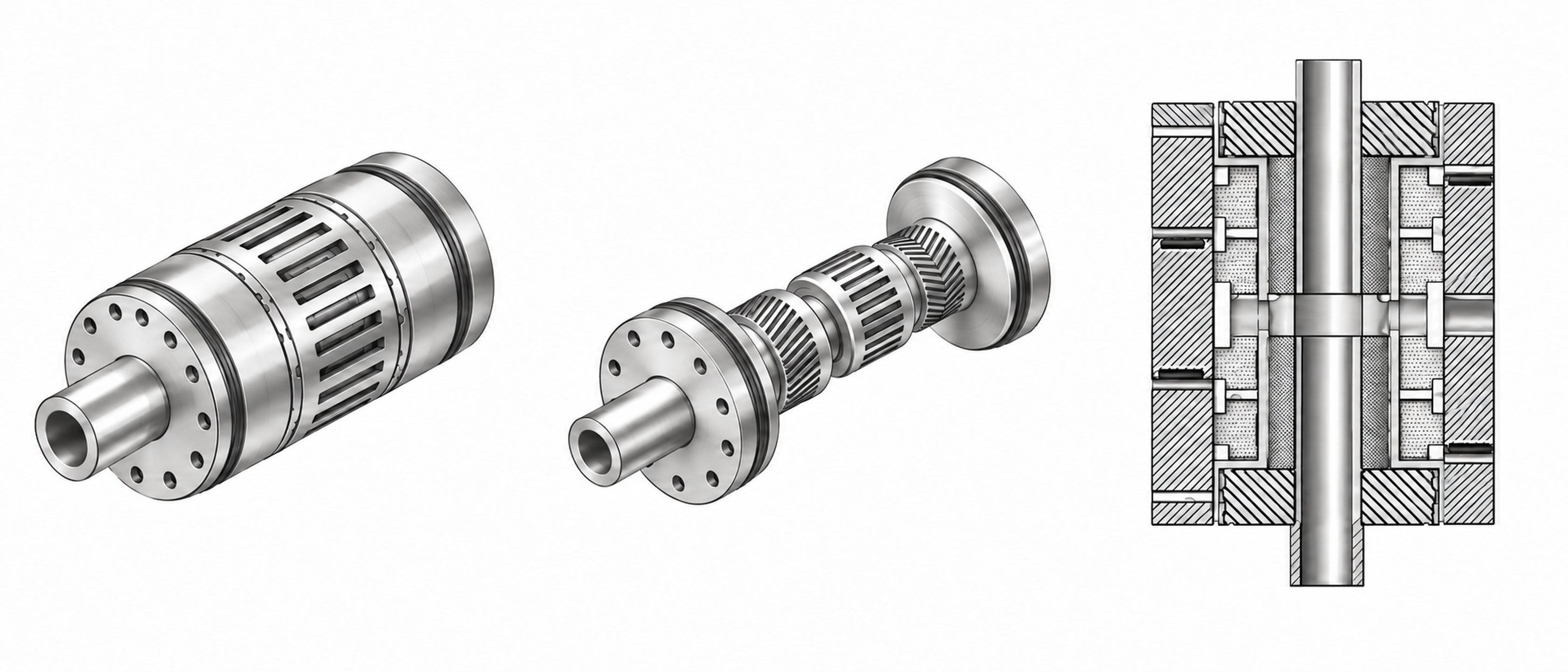
Figure 3.3. Assembled, exposed, and sectional rotor-stator homogenizer configurations. The views show sequential processing zones and clearances.
3.4 Feed order and premix quality
The state of the feed establishes the initial conditions for emulsification, including phase continuity, droplet size, and the location of the stabilizer. In many formulations, the intended continuous phase is established before the second liquid is introduced. Emulsifier placement should reflect solubility, adsorption kinetics, and the possibility of unwanted aggregation. Introducing the dispersed liquid near the head intake can shorten the interval before intense deformation, provided that the feed is diluted adequately and does not create a concentrated stream that bypasses mixing or causes local inversion.
Premixing should produce a feed that enters the mixing head consistently and remains stable long enough for further processing. A very coarse or segregating feed can cause fluctuating torque, irregular loading, and a broad distribution of treated droplets. Excessive premixing can add unnecessary thermal exposure and oxidation before the principal emulsification step. The required premix is therefore defined by flowability, phase topology, feed uniformity, and stability over the transfer interval.