
Technical publication
Back to publications
Industrial applications
Emerging Frontiers in Hydrodynamic Cavitation
okozyuk.com
Published
Read complete publication for whole-document Find and printing. Browser Find and native printing on this reader include only loaded content.
8 Petroleum Liquids, Oil Sludge, and Hydrocarbon Residues
8.1 Mechanisms and Evidence Boundaries
Hydrodynamic cavitation has been proposed for heavy crude oil, fuel oil, bitumen, refinery residues, oily wastewater, and accumulated oil sludge. Mechanical effects can disperse asphaltene and mineral agglomerates, disrupt wax crystal networks, reduce droplet size, and improve contact among water, oil, catalysts, or chemical additives. Thermal and radical effects may alter selected molecules, but many reported viscosity changes also include contributions from bulk heating, dilution, temporary shear history, and sampling temperature [58,59].
Claims of permanent molecular cracking or increased light fraction yield require especially careful verification. The control must match temperature history, residence time, pressure, and any diluent or catalyst. Gas chromatography, simulated distillation, sulfur species, asphaltene molecular distribution, pour point, viscosity recovery after storage, and a complete energy balance are needed to distinguish true compositional change from reversible rheological conditioning [58].
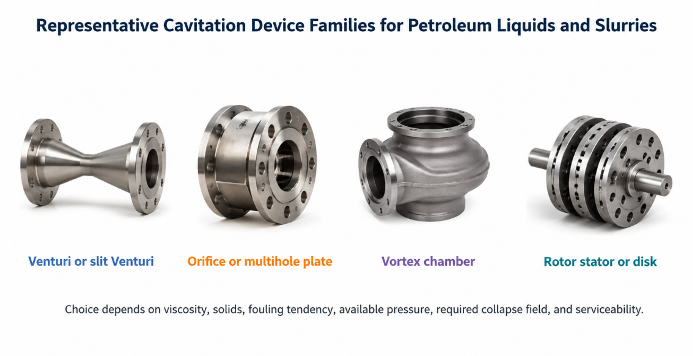
Figure 8.1. Representative cavitation device families for petroleum liquids and slurries. [70].
8.2 Viscosity, Wax, and Fractional Composition
Heavy petroleum liquids often contain a network of wax crystals, asphaltene aggregates, resins, water droplets, and fine mineral particles. Cavitation can temporarily lower apparent viscosity by disrupting this network and can improve pumpability when the treated liquid remains above the wax appearance temperature. The benefit may decay as the structure rebuilds, so viscosity should be measured at a defined shear rate, temperature, and aging time rather than immediately at the cavitator outlet [58,59].
is the relative viscosity reduction, μ₀ is the initial viscosity, and μₜ is viscosity after a stated treatment and aging protocol at the same measurement temperature and shear condition.
is the mass fraction distilled below the declared cut temperature Tcut. The cut temperature, pressure, analytical method, and untreated control must be reported.
Kuimov et al. concluded that promising experimental results have not yet resulted in broad refinery adoption because there is no unified method for comparing cavitation intensity across different oils and devices. A cavitation number based on water assumptions can be misleading in hot, viscous, multicomponent hydrocarbons containing dissolved gas and exhibiting non Newtonian behavior. Device geometry, vapor pressure model, gas release, rheology, and thermal balance must therefore be evaluated together [58].
8.3 Oil Sludge and Liquid Oil Waste Processing
Oil sludge treatment is a multiphase separation problem rather than a single cavitation reaction. The reviewed Russian process concept combines coarse separation, settling, dewatering, cavitation treatment, thermal conditioning, rectification, and conversion of residual solids to road construction products. Disk, rotor impulse, and resonant hydrodynamic generators were proposed to disperse solids, break associations, homogenize liquid wastes, and improve flow before conventional separation or distillation [59].
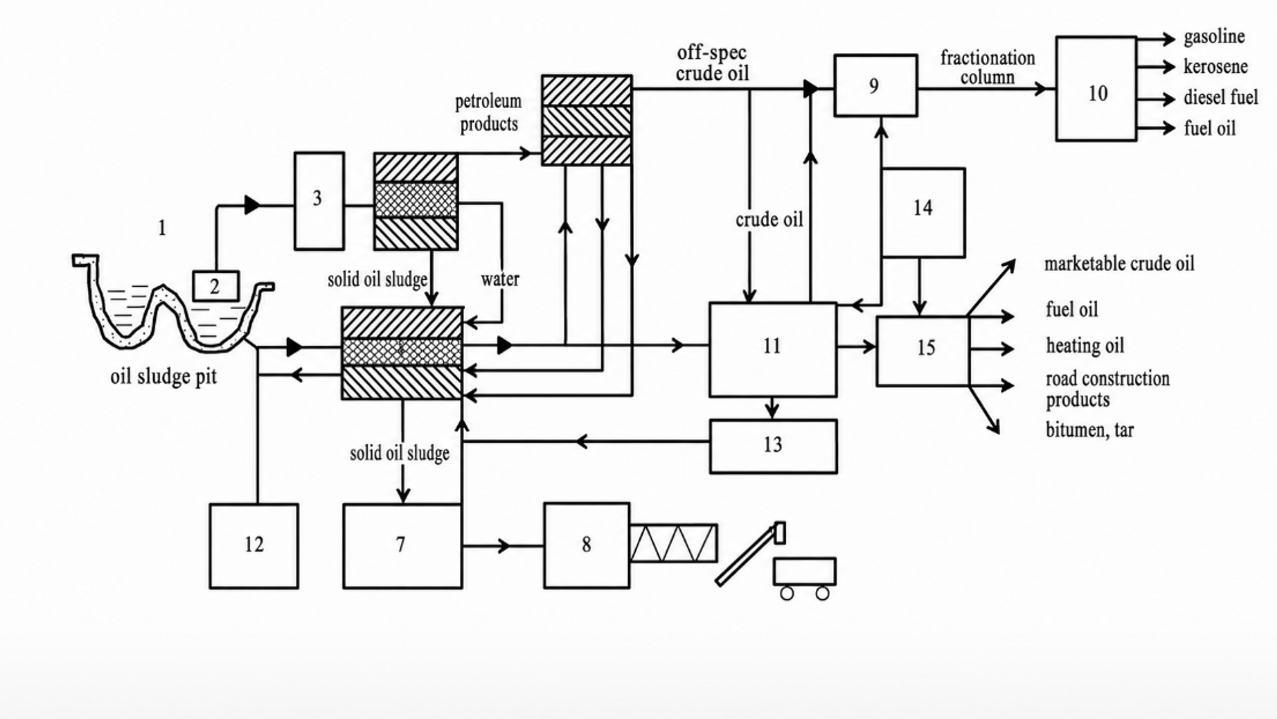
Figure 8.2. Integrated process concept for solid oil sludge and liquid oil waste treatment. [59].
The process flow emphasizes a sound engineering principle: cavitation is located where it improves a downstream unit operation. Free water and coarse solids are removed before high energy treatment; cavitation then improves homogenization or releases entrained phases; settling, centrifugation, rectification, or product finishing performs the actual separation. This arrangement reduces cavitator wear and prevents the hydraulic device from being assigned duties that are better performed by separators.
8.4 Equipment Selection, Wear, and Validation
Static Venturi and orifice devices are attractive when clean liquid is already pressurized, but fibrous solids, coke, sand, and high viscosity can cause blockage or severe pressure demand. Vortex and rotor stator devices provide larger passages and repeated exposure, although rotating seals and close clearances increase maintenance. Resonant devices can amplify pressure oscillations but must be designed for fatigue life. Materials should be selected for erosion, corrosion, temperature, and compatibility with sulfur compounds, solvents, and abrasive solids.
is specific electrical energy per treated volume, Pel is measured motor input, t is operating time, and is the actual treated volume. For recirculating systems, must not be replaced by cumulative loop flow unless the distinction is stated.
Table 8.1. Minimum validation set for petroleum cavitation trials
| Category | Required measurements | Reason |
|---|---|---|
| Feed definition | Density, viscosity curve, water, solids, wax, asphaltenes, sulfur, boiling distribution | Petroleum feed variability can exceed the treatment effect. |
| Hydraulics | Flow, pressure at defined locations, temperature, backpressure, gas fraction, power | Separates cavitation from simple heating and throttling. |
| Product response | Viscosity after controlled aging, pour point, particle size, emulsion stability, distillation curve | Distinguishes temporary dispersion from persistent compositional change. |
| Mechanical integrity | Erosion coupons, vibration, bearing and seal condition, fouling, pressure drift | High solids and vapor collapse can damage the device or change its operating window. |
| Economics and safety | Energy, maintenance, hazardous area classification, vent treatment, cleaning frequency | Determines whether a laboratory effect can be deployed in a refinery or waste facility. |