Technical publication
Back to publications
Emerging Frontiers in Hydrodynamic Cavitation
okozyuk.com
Published
Emerging Frontiers in Hydrodynamic Cavitation
Abstract
Hydrodynamic cavitation is increasingly applied as a multifunctional process intensification method in systems where pressure reduction, bubble generation, interfacial renewal, collapse, and repeated hydraulic exposure can be exploited for different engineering objectives. This article evaluates emerging applications in cooling water conditioning, commercial aquatic systems, aeration, flotation, gas stripping, biomass lysis and extraction, petroleum processing, critical mineral recovery, cavitating jet cleaning, and drilling. The analysis distinguishes collapse dominated treatment from stable cavity and microbubble regimes and emphasizes that pressure drop alone does not define process severity. For each application, the relevant mechanism, performance metric, downstream separation requirement, scale up variable, and principal failure mode are identified. Reviewed evidence shows that cavitation can intensify bulk crystallization, oxygen transfer, fine particle flotation, degassing, mass transfer, surface cleaning, and rock weakening when the hydraulic state is matched to the required function. The same mechanisms can also cause erosion, fragmentation, gas redissolution, contaminant release, excessive fines, or unproductive energy consumption. Scale up therefore requires preservation of both local cavitation behavior and system exposure, together with measured flow, pressure, temperature, gas fraction, power, wear, and application specific response. The most defensible design approach is function first: define the required physical effect, integrate cavitation with the necessary separation and control operations, and validate performance under realistic feed variability and extended operation.
1 Introduction
The common hydraulic definitions, energy boundaries, residence time expressions, uncertainty requirements, and scale translation principles used in this article are consolidated in the general hydrodynamic cavitation framework. The present analysis applies that framework to emerging applications and develops the mechanisms, performance metrics, design constraints, and acceptance criteria that are specific to each application.
Hydrodynamic cavitation is the formation and dynamic evolution of vapor or gas cavities caused by a local pressure reduction in a moving liquid. The pressure decrease may be generated in an orifice, Venturi throat, vortex core, nozzle, rotating gap, valve, or fluidic oscillator. When cavities enter a region of higher pressure, they may collapse violently or persist as dispersed gas bubbles depending on gas content, size, interfacial stabilization, and the pressure recovery history. These distinct hydraulic states explain why the same general technology can function as an advanced oxidation reactor, microbubble generator, degasser, flotation contactor, or mechanical erosion tool [1-5].
The applications considered in this article extend beyond the conventional categories of pollutant oxidation and bulk mixing. Their technical significance arises from three capabilities that can be combined within a hydraulic device. Cavitation can create a large gas liquid or vapor liquid interfacial area, collapse can generate localized pressure pulses, shear, microjets, and transient chemical activity, and the device can operate continuously in a side stream loop, flotation reactor, submerged nozzle system, or drilling fluid circuit. The principal design problem is therefore to select the useful cavitation function and suppress competing effects.
Cooling water treatment uses the hydrodynamic and equilibrium consequences of cavitation to promote bulk mineral precipitation, expose circulating microorganisms to a high stress zone, and release carbon dioxide, while a separate cyclone or filter removes precipitated solids. Aeration and flotation use injected or dissolved gas to generate fine bubbles. Degassing uses the low pressure region to activate dissolved gas nuclei but requires downstream disengagement or venting. Cavitating jet cleaning and drilling deliberately position collapse near a solid surface so that pressure pulses and microjets remove deposits or damage rock. Lithium and critical mineral processing are less mature; the best supported role is process intensification within conventional leaching, attrition, carbonation, flotation, or crystallization trains [13,15-19,35-37].
A recurring design error is to specify a cavitation device only by pressure drop. Pressure drop defines an energy input but does not fully characterize the two phase flow. Cavitation number, geometry, dissolved gas content, gas injection ratio, fluid properties, backpressure, residence time, pass count, and the location of pressure recovery determine whether the device produces collapse dominated cavitation, a stable gas cavity, a dispersed microbubble plume, or hydraulic choking. These distinctions govern the applications evaluated below.
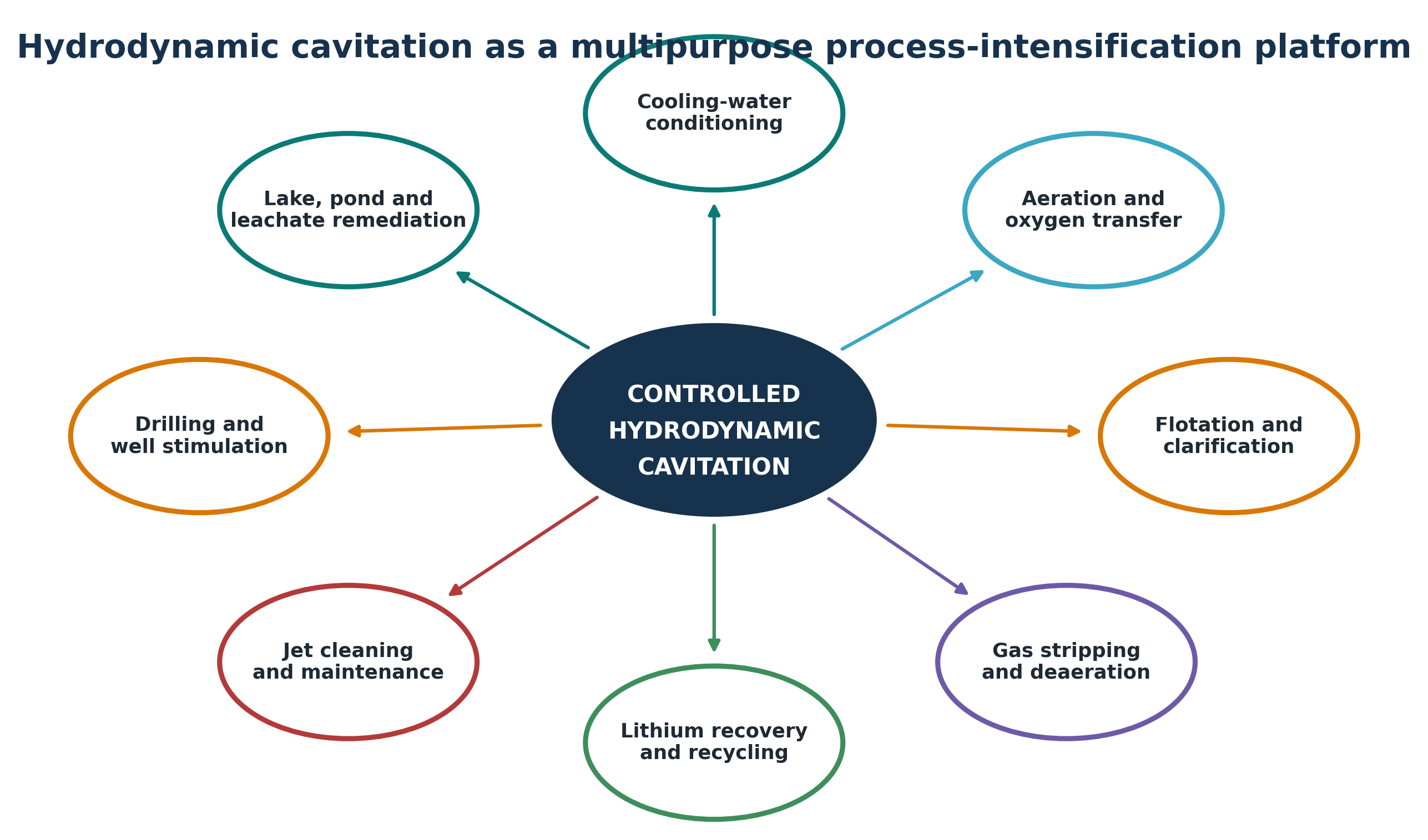
Figure 1.1. Hydrodynamic cavitation as a multipurpose process intensification platform. [70].
2 Common Engineering Framework
The pressure conversion, cavitation inception, bubble collapse, hydraulic power, specific energy, and scale up relations used in this article follow the common engineering framework established for hydrodynamic cavitation. Each application is evaluated by the additional mechanism that determines useful performance, including gas transfer and disengagement, bubble particle capture, crystallization, leaching, jet impact, or drilling hydraulics.
3 Cooling Water and Commercial Aquatic Systems
3.1 Treatment Objectives and Process Architecture
Open recirculating cooling towers and evaporative condensers continuously concentrate dissolved salts because essentially pure water is lost by evaporation while minerals remain in the circulating inventory. The operating program must simultaneously control mineral scale, corrosion, suspended solids, algae, bacteria, and microbiologically influenced corrosion while preserving heat transfer performance. Conventional programs use scale inhibitors, corrosion inhibitors, oxidizing or nonoxidizing biocides, dispersants, pH control, blowdown, and filtration. Controlled hydrodynamic cavitation systems were developed as nonchemical or reduced chemical side stream alternatives [7-12].
A practical cooling water installation is a treatment train rather than an isolated cavitation chamber. One side stream passes basin water through the cavitation device, while another removes precipitated mineral solids and environmental debris through a cyclone, automatic screen, sand filter, bag filter, or equivalent separator. Conductivity or constituent concentration controls blowdown, and corrosion coupons, bacterial counts, deposit inspection, heat transfer measurements, and makeup water chemistry provide verification. Reviewed field reports show that solids removal becomes increasingly important as cycles of concentration rise [7-13].
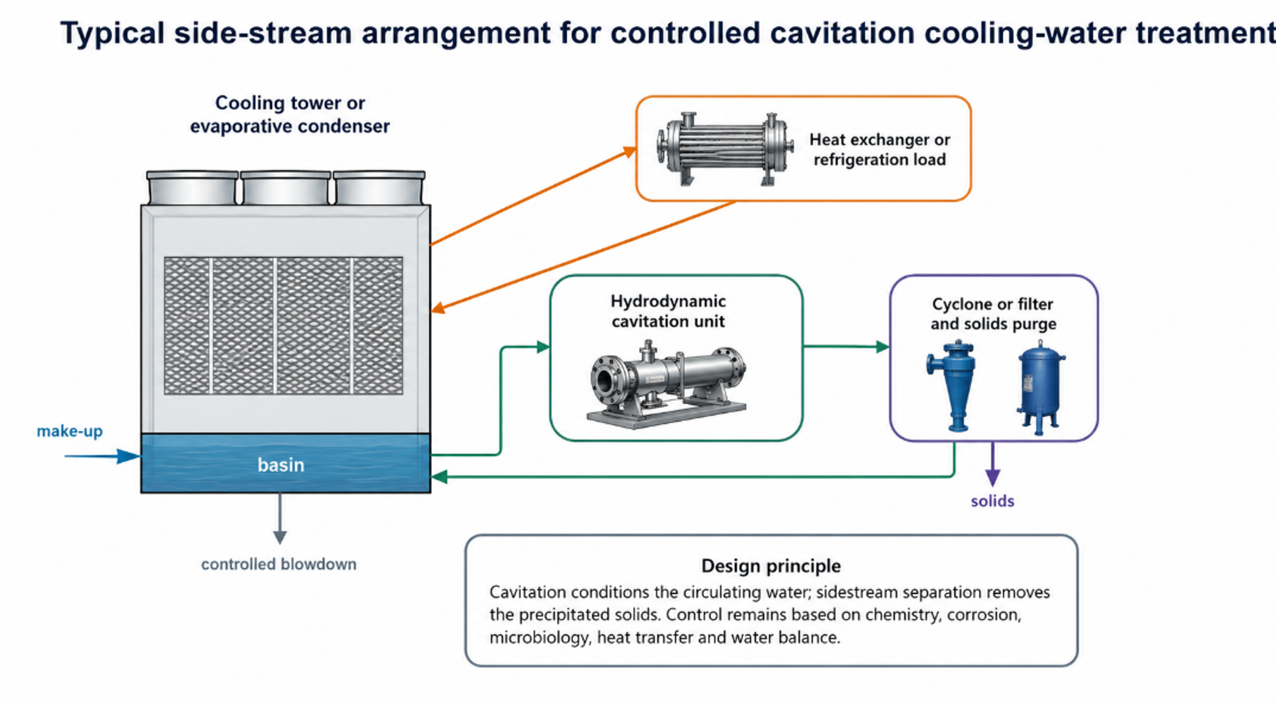
Figure 3.1. Typical side stream arrangement for controlled cavitation cooling water treatment. [7-13].
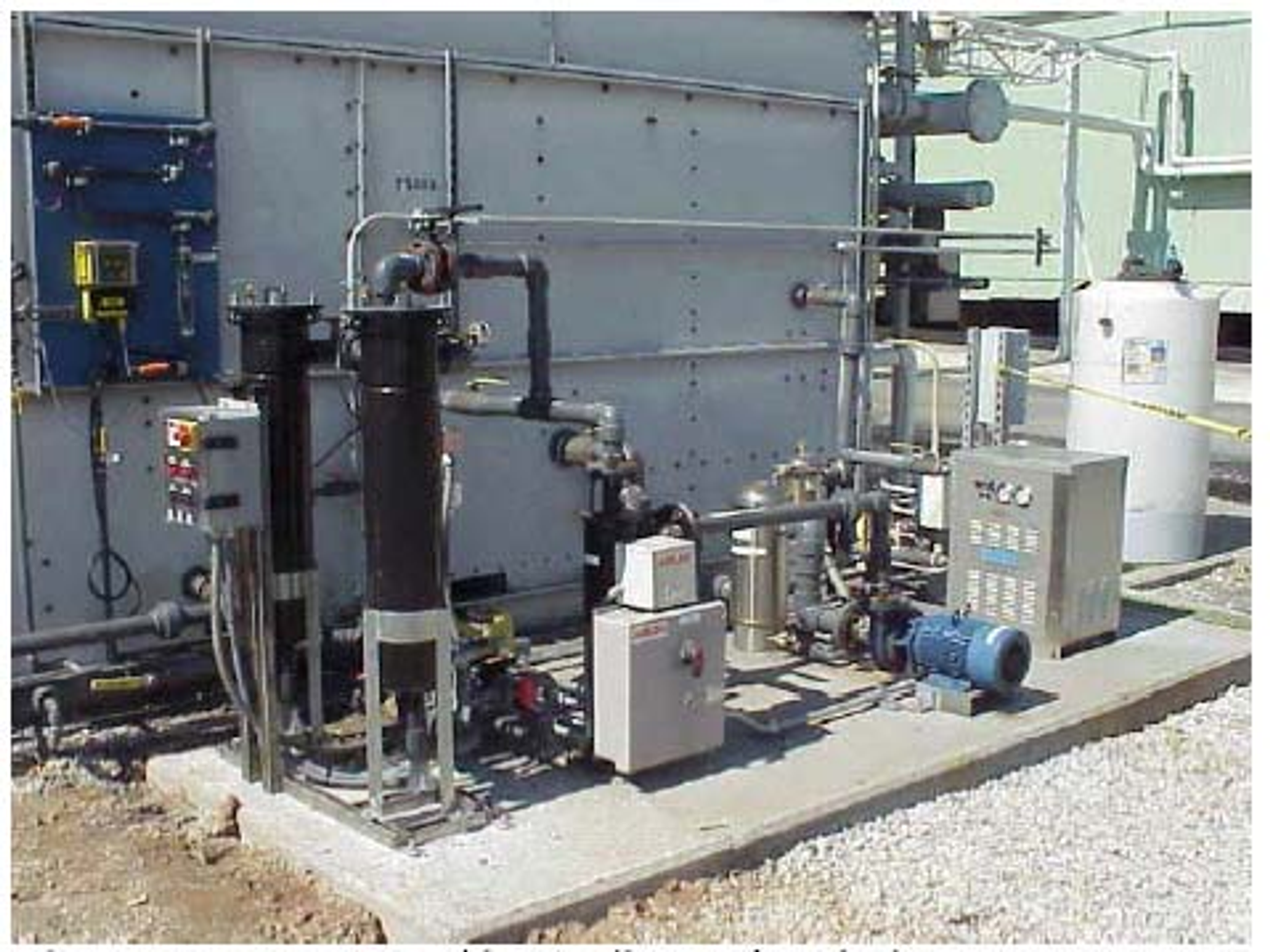
Figure 3.2. Field installed hydrodynamic cavitation cooling water skid with pumps, cavitation unit, cyclone, bag filtration, controls, and piping. [8].
3.2 Cooling Tower Water Balance and Concentration Control
Cycles of concentration compare a conservative dissolved constituent in the circulating water with the same constituent in the makeup water. Conductivity is convenient but can underestimate the true concentration factor when calcium carbonate and other salts precipitate. The Alcoa comparison therefore concluded that sodium, magnesium, potassium, and sulfate ratios were more reliable at high cycles than conductivity alone [8].
and are concentrations of a conservative constituent in circulating and makeup water. The overall water balance for the system is governed by the mass flow rates:
M is makeup flow, E is evaporation, B is blowdown, and includes drift and other measured losses.
Assuming the selected constituent remains fully soluble and undergoes no precipitation or chemical reaction, the steady-state blowdown requirement can be approximated by:
This simplified steady-state expression quantitatively illustrates how operating at elevated cycles of concentration effectively reduces blowdown volume.
3.3 Scale Control by Gas Release and Bulk Crystallization
The central scale control concept is to promote calcium carbonate formation in the bulk water, where particles can be removed, rather than on the hottest heat transfer surface. Pressure reduction can release dissolved carbon dioxide and alter carbonate equilibrium; local heating and intense mixing can accelerate nucleation; recirculated precipitate provides seed surface. The overall bicarbonate decomposition is represented by the bicarbonate equilibrium below. Chemistry is reversible and depends on pH, alkalinity, calcium activity, ionic strength, temperature, and gas exchange.
This expression represents coupled carbonate equilibria rather than a single elementary reaction.
The Langelier Saturation Index compares measured pH with the calculated calcium carbonate saturation pH, pHs. A slightly positive LSI indicates a scale forming tendency but does not identify where precipitation will occur.
Kim and coworkers investigated a semi batch hyperkinetic vortex crystallization process for calcium rich electronics wastewater. At stable operation, the feed calcium averaged 162.6 mg/L, and the effluent averaged 48.5 mg/L; removal ranged from 62.8 to 76.1%, with a mean of 70.2%. Cavitation produced smaller, more spherical calcite particles with greater specific surface area, supporting clarification and reducing the likelihood of tenacious deposition in piping [13]. This result supports the bulk crystallization mechanism, although the wastewater chemistry and sodium carbonate dosing differ from ordinary cooling tower water.
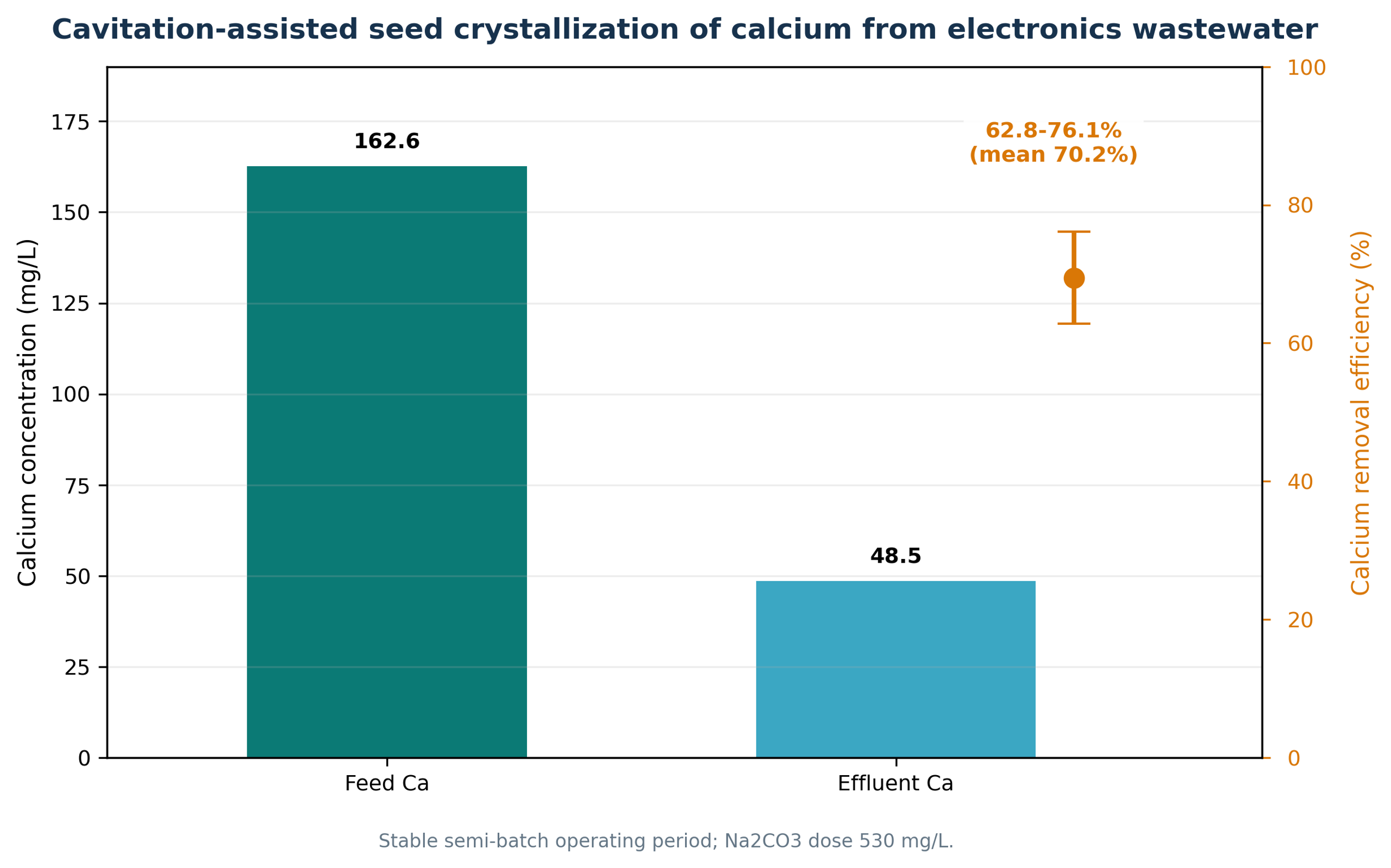
Figure 3.3. Cavitation assisted seed crystallization of calcium from electronics wastewater. [13].
3.4 Microbiological and Corrosion Control
Microorganisms passing through the active cavitation zone are exposed to pressure fluctuations, shear, microjets, and transient radicals. This is a pass through treatment. Unlike chlorine, bromine, ozone residual, or another persistent biocide, cavitation does not automatically protect remote dead legs, drift eliminators, fill surfaces, or established biofilms. This distinction is particularly important for Legionella risk management. In the automotive field study, total heterotrophic plate count stabilized near 10⁴ CFU/mL during a two month trial without chemical disinfectant, and no Legionella was detected in either the preceding chemical period or the cavitation trial. The authors stated that longer testing and formal field verification were required and that the process may not be appropriate as the sole disinfectant in every system [7].
Corrosion response is similarly conditional. Cavitation may remove carbon dioxide, reduce biofilm, avoid corrosive chemical shocks, and maintain alkaline water. Conversely, higher cycles increase dissolved solids and scaling indices; oxygen remains present; and mechanically generated solids can create under deposit conditions if not removed. The automotive trial reported copper and mild steel corrosion rates equivalent to or better than the chemical baseline, but galvanized steel required attention [7]. The six month Alcoa comparison found the chemical tower had the lowest average corrosion rate, although the nonchemical rates remained within the study's industry criteria [8]. These results are not contradictory: they demonstrate that source water hardness, orthophosphate, metallurgy, deposit removal, and operating cycle determine the result.
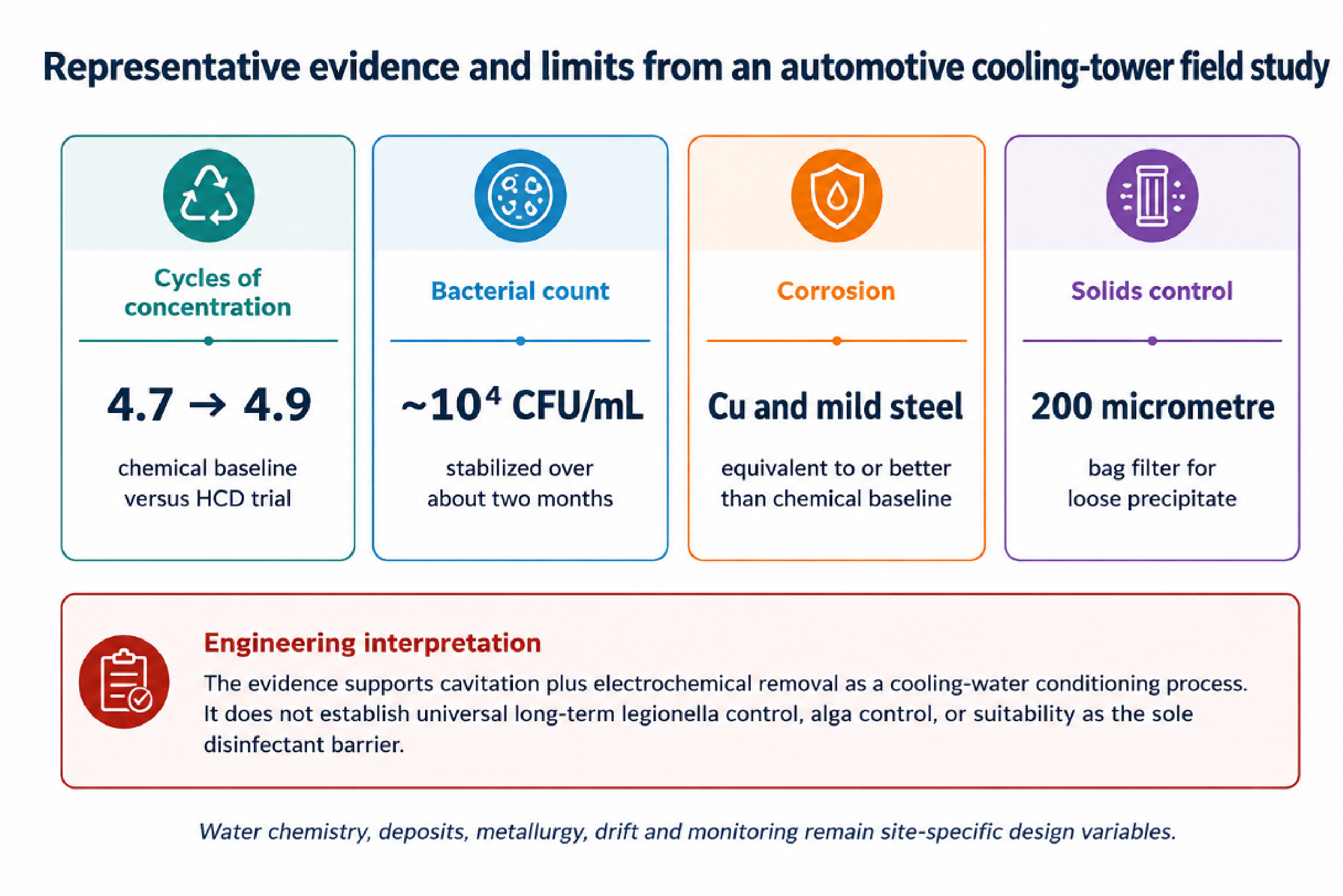
Figure 3.4. Representative evidence and limits from an automotive cooling tower field study. [7].
3.5 Field Evidence and Design Conclusions
Table 3.1. Selected cooling water evidence from the reviewed sources
| Source and setting | Reported result | Interpretation and limitation |
|---|---|---|
| Automotive test facility, approximately 7000 gal system [7] | Bacterial count near 10⁴ CFU/mL; CoC 4.9 vs 4.7 chemical baseline; Cu and mild steel corrosion equivalent or better | Two month trial; no persistent residual; longer Legionella and heat transfer verification needed |
| Three nominally identical Alcoa evaporative coolers [8] | HDC and pulsed power towers gave better planktonic and sessile microbial control; HDC coupons remained below 10⁶ CFU/cm² | Chemical tower had best corrosion; water savings were not statistically different at identical control settings; side stream solids removal was decisive |
| Heineken evaporative condensers, ISPT project [14] | Visual scaling equal to or less than chemical treatment; chemical analyses indicated successful corrosion and microbial control; reported payback below two years | Project summary rather than a fully detailed peer reviewed trial |
| Electronics wastewater seed crystallization unit [13] | Mean calcium removal 70.2%; smaller and more spherical calcite after cavitation | Strong evidence for bulk crystallization, but chemistry included Na₂CO₃ dosing and differs from cooling tower makeup |
| Commercial and government reports [9–12] | Case histories report chemical reduction, higher cycles and water savings | Performance data quality varies; independent verification and local compliance remain essential |
| Cooling water design conclusion. Controlled hydrodynamic cavitation is best specified as one component of a side stream conditioning system. A robust design includes solids separation, chemistry control, corrosion verification, microbiological verification, basin cleaning, drift management, and a contingency biocide strategy. It should not be presented as a universal chemical free replacement without site specific validation. |
|---|
3.6 Commercial Aquatic Water Systems
Commercial swimming pools and spas present a related but more tightly regulated recirculating water problem. The objective is not to eliminate disinfectant, but to reduce the load placed on the chemical program while maintaining a continuously verifiable disinfectant residual, acceptable combined chlorine, clear water, stable pH, adequate filtration, and pathogen control. An inline cavitation device is therefore an adjunct to circulation, filtration, heating, chemical feed, and code compliant disinfection rather than a substitute for them [52,66].
The AquaRev engineering assessment describes a passive inline device installed in an existing return loop. The reported laboratory and field results include a 36% reduction in combined chlorine, a 54% reduction in chlorine demand, and operational reductions in salt, acid, carbon dioxide, evaporation loss, and energy use. These results are specific to the evaluated device and test program and should be treated as qualification targets for facility verification rather than universal guarantees across pool chemistry, bather load, temperature, or hydraulic conditions [52].
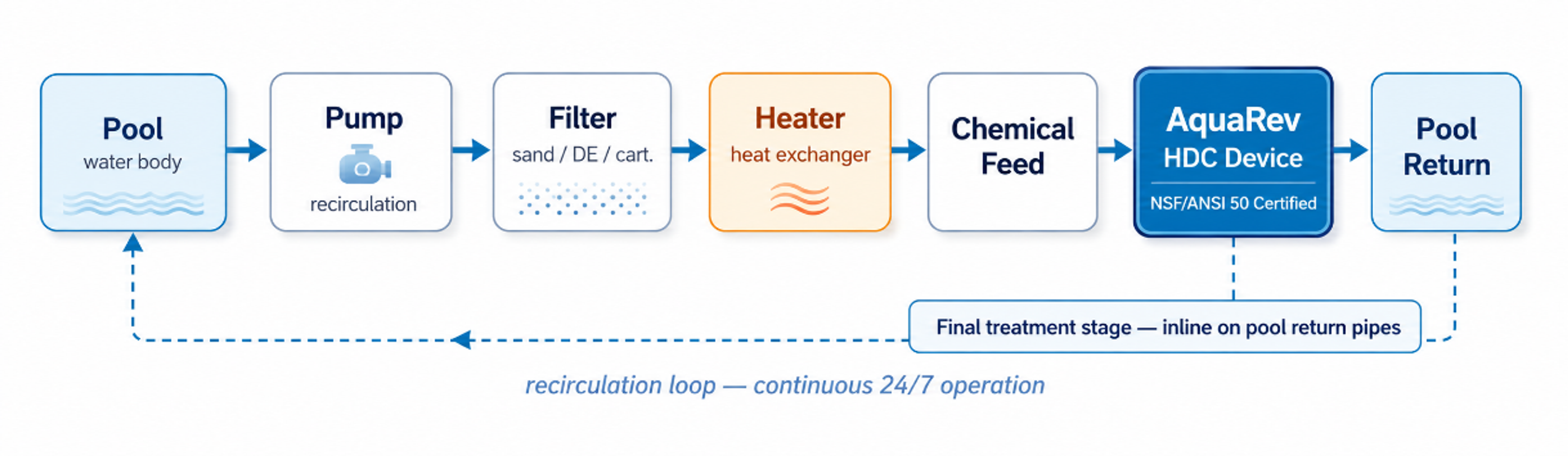
Figure 3.5. Typical integration of a passive hydrodynamic cavitation device into a commercial pool recirculation loop.
Hydraulic exposure is best expressed by treated turnovers rather than by elapsed clock time alone. If the device processes a flow Q for an evaluation period T in a pool or basin of volume V, the nominal number of treated turnovers is:
Nₜ is the nominal treated turnover count, Q is the device flow rate, T is the evaluation period, and V is the recirculating water volume. This metric does not imply perfect mixing, so tracer testing or a verified circulation model is required for large or irregular basins.
A defensible commissioning trial maintains comparable occupancy, temperature, filtration rate, disinfectant control logic, and weather exposure before and after installation. At minimum, the trial should track free and combined chlorine, oxidation reduction potential, pH, alkalinity, cyanuric acid where applicable, turbidity, makeup water, evaporation, filter backwash, chemical consumption, pump power, microbial indicators, and complaints related to odor or irritation. Any reduction in chemical use must be accompanied by evidence that the required disinfectant residual and microbial barriers were maintained [52,66].
Table 3.2. Verification framework for commercial aquatic systems
| Verification category | Measurements | Acceptance principle |
|---|---|---|
| Hydraulics | Device flow, inlet and outlet pressure, turnover count, bypass position | Operate inside the qualified pressure and flow window without compromising code required recirculation. |
| Water chemistry | Free and combined disinfectant, pH, alkalinity, cyanuric acid, conductivity, calcium hardness | Compare with a matched baseline and maintain all regulatory limits. |
| Water quality | Turbidity, particle counts, visual clarity, odor, surface deposits | Improvement must not be achieved by weakening filtration or disinfectant control. |
| Microbiological performance | Heterotrophic counts and facility specific pathogen monitoring | Treat cavitation as a supplementary barrier unless independent validation establishes a primary disinfection claim. |
| Resource use | Chemical mass, makeup and drain water, pump electricity, heating energy | Normalize by occupancy, operating hours, weather, and treated water volume. |
4 Aeration and Gas Liquid Contacting
4.1 Mechanism of Self Aspiration and Fine Bubble Generation
A cavitation aerator converts liquid pressure into a low pressure cavity, introduces air or oxygen into that cavity, and then disperses the gas during pressure recovery. In a Venturi or supercavitation device, the gas can be drawn in without a separate compressor when the throat pressure is sufficiently low. In vortex devices, gas may enter the central low pressure core and be broken into bubbles by shear and turbulent pressure fluctuations. The active device therefore performs gas induction, primary breakup, and hydraulic mixing in a single flow path [15-17].
The gas transfer benefit is governed not by collapse alone but by bubble size distribution, gas holdup, circulation, and renewal of the gas liquid interface. Small bubbles provide high interfacial area but rise slowly and may coalesce, whereas larger bubbles provide greater circulation and buoyant transport but less area per unit gas volume. Practical aeration and flotation systems can therefore benefit from a polydisperse bubble population.
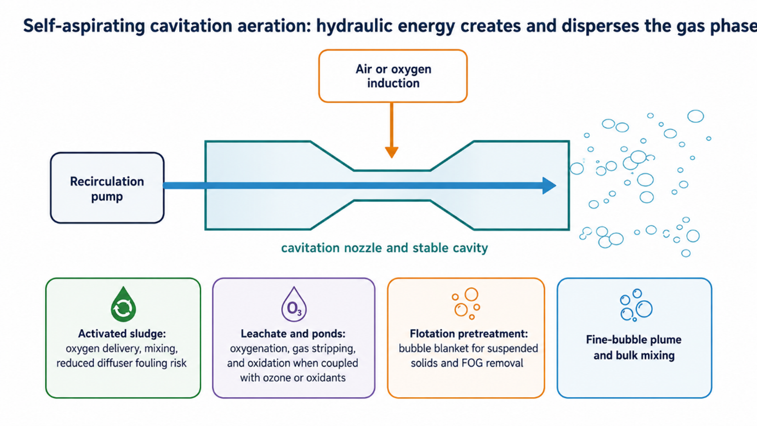
Figure 4.1. Self-aspiration cavitation aeration: hydraulic energy creates and disperses the gas phase. [15-17].
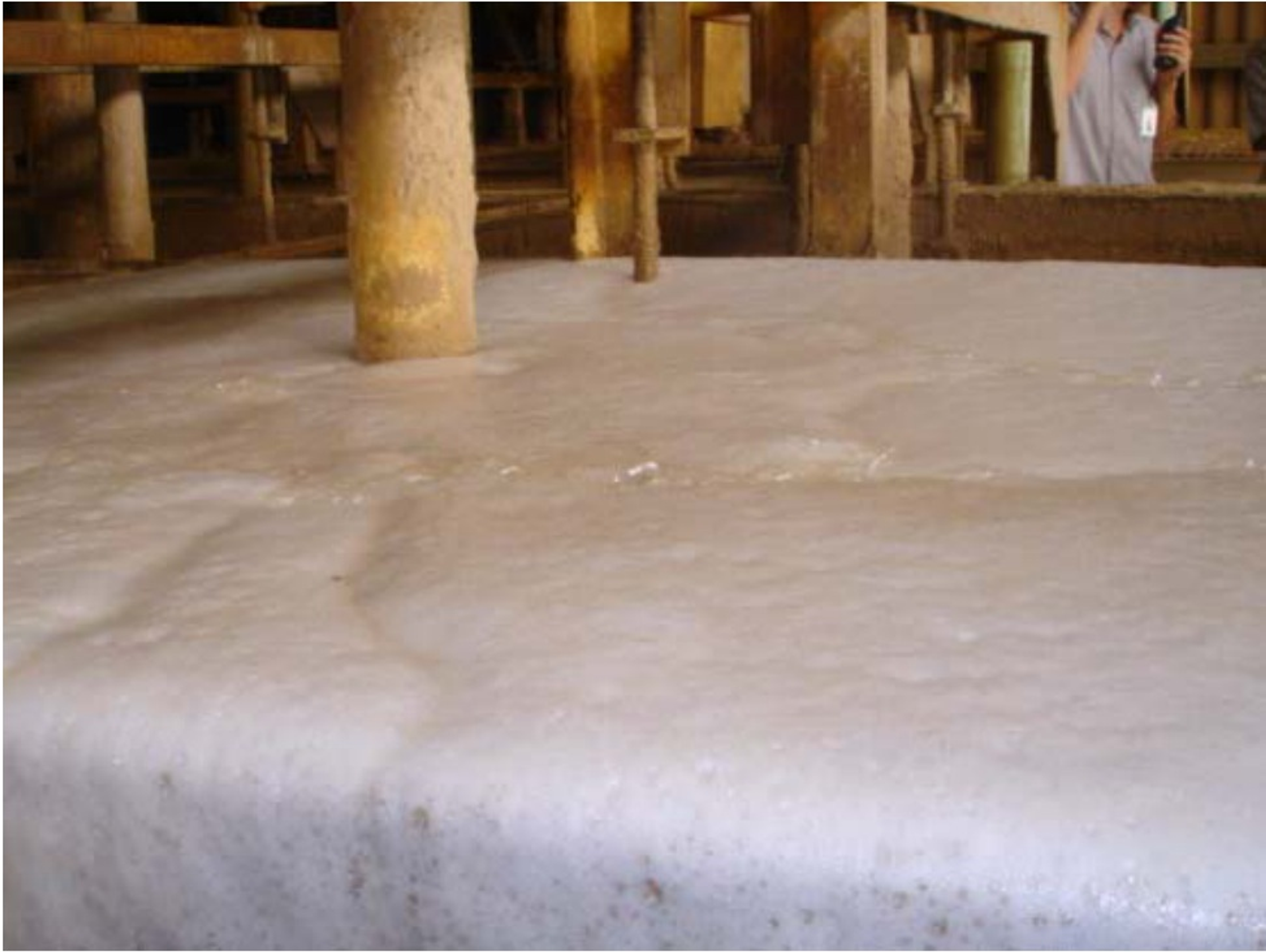
Figure 4.2. Dense bubble blanket generated by a cavitation sparging system in an industrial flotation or aeration vessel. [25].
4.2 Oxygen Transfer Equations and Performance Metrics
The transient dissolved oxygen balance in a well-mixed aerobic basin includes transfer from the bubbles and consumption by the biomass. For clean water testing, oxygen uptake is omitted and the exponential approach to saturation is used to estimate kLa. Wastewater correction factors are then applied for salinity, temperature, surfactants, solids, and the ratio between process water and clean water mass transfer. The mass balance governing dissolved oxygen dynamics in the system is expressed as:
is dissolved oxygen concentration, is the equilibrium concentration under the prevailing gas composition and pressure, is the volumetric mass transfer coefficient, and OUR is volumetric oxygen uptake rate.
This clean water form is used to fit transient aeration data when OUR is negligible.
OTR is oxygen transfer rate and V is liquid volume. Standard aeration efficiency () is defined as:
Standard aeration efficiency (SAE) is standardized oxygen transfer rate divided by electrical power, commonly reported as kg O2/kWh.
The alpha factor α accounts for the effect of process water, surfactants, solids, and biomass on mass transfer. Beta and temperature corrections are also required for rigorous standardization.
The 2009 supercavitation report described a 15 kW Cav Jet installed in a domestic activated sludge basin. The supplementary pure oxygen demand reportedly declined from about 1200 to 600 m³/d during one operating period and from about 1000 to 300 m³/d in a second period, while the treatment plant continued to meet its reported carbon and nitrogen performance. The authors estimated approximately 2.5 kg O2/kWh, comparable to membrane diffusers under the cited conditions [15]. These field observations are valuable but should be interpreted with caution because the plant contained multiple aeration systems and the trials did not isolate every operating variable. The same report noted that point DO probes showed lower concentrations during Cav Jet operation than conventional aeration, even though long term oxygen demand decreased. This discrepancy reinforces the need for off gas testing, basin wide DO mapping, OUR measurement, and standardized oxygen transfer testing.
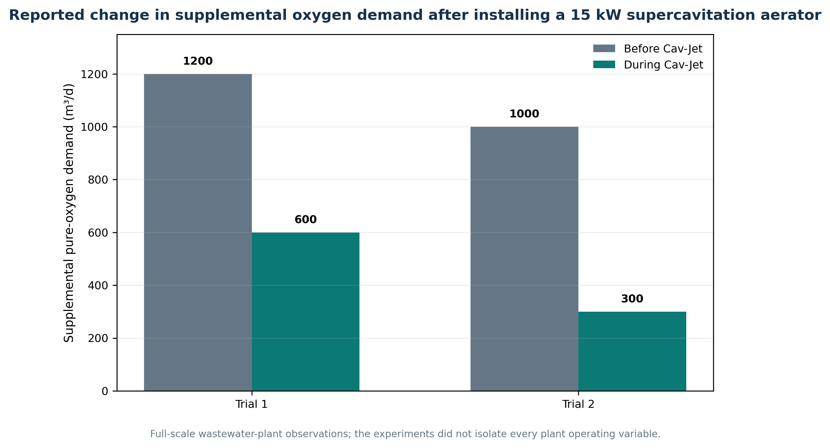
Figure 4.3. Reported change in supplemental pure oxygen demand after installation of a 15 kW supercavitation aerator. [15].
Recent vortex device experiments explicitly separated degassing from aeration. Nayak, Ganjare, and Ranade showed that circulating saturated water through the vortex device without air reduced dissolved oxygen and that the degassing rate increased with pressure drop. When air was introduced, the same device accelerated aeration, produced effective kLa values up to approximately 70 h⁻¹ in the reported apparatus, and achieved dissolved oxygen concentrations above atmospheric equilibrium because bubbles were generated and pressurized within the circulating system [17]. The result demonstrates that cavitation can either remove dissolved gas or intensify gas absorption depending on gas injection and boundary conditions.
4.3 Wastewater Pretreatment and Cavitation Air Flotation Clarifiers
In cavitation air flotation (CAF), the cavitation device is principally a bubble generation and contacting stage. It does not replace equalization, screening, coagulation, flocculation, hydraulic separation, skimming, or sludge handling. The feed is conditioned so that fibers, proteins, fats, oil droplets, dye aggregates, or other suspended matter can attach to bubbles. The bubble particle aggregates rise into a float blanket that is mechanically removed. A high energy contactor and a low turbulence separator are therefore arranged in series [23-30].
For pulp mills, the bubble blanket captures fibers and mineral fillers from whitewater and permits reuse of clarified water. For slaughterhouses and food plants, the principal target is fats, oils, grease, blood solids, and proteins that otherwise impose a high BOD and COD load on biological treatment. In refinery and petrochemical service, free oil is normally removed upstream by gravity, while flotation targets dispersed and chemically destabilized droplets. The term CAF clarifier should not imply that raw emulsions can be separated without chemistry. Stable emulsions often require pH adjustment, coagulant, cationic polymer, or emulsion breaker before microbubbles can produce a removable float.
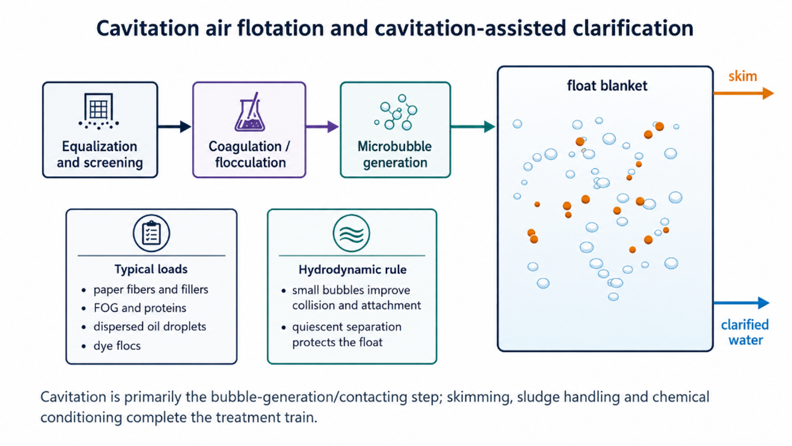
Figure 4.4. Cavitation air flotation and cavitation assisted clarification. [23,27-33].
4.4 Biological Activated Sludge Basins
Activated sludge requires oxygen for carbon oxidation and nitrification and hydraulic energy to suspend biomass and distribute substrate. A cavitation aerator can supply both, but the design objective is not maximum collapse intensity. Excessive localized shear can fragment flocs, increase turbidity, or expose cells to repeated stress, whereas insufficient basin circulation produces solids deposition and low DO zones. The preferred design creates the fine bubble plume in the hydraulic device and dissipates the bulk of the jet momentum in a controlled mixing pattern.
Control should be based on process demand rather than a fixed pump speed. Useful signals include basin DO at multiple elevations, ammonia, oxidation reduction potential, airflow or aspirated gas flow, pump pressure, mixed liquor suspended solids, sludge volume index, and OUR. In nutrient removal plants, continuous high DO can be undesirable because anoxic zones are required for denitrification. The aerator should therefore be integrated with process zoning and ammonia- or DO based control rather than operated as an isolated oxygen generator.
4.5 Eutrophic Ponds and Lake Remediation
Floating or shore mounted cavitation stations can recirculate oxygen depleted water, aspirate air or oxygen, and return a microbubble plume. The immediate benefits can include higher DO, water column circulation, reduced hydrogen sulfide and odor, and lower acute fish kill risk. When ozone is injected, cavitation can improve ozone dispersion and utilization and contribute additional oxidation. At pilot scale, Li and coworkers reported chlorophyll a removal of 78.8% for HC/O3 compared with 62.3% for ozone alone, ozone utilization of 94.8% compared with 64.5%, and total energy of 8.25 versus 8.89 kWh/m³ [18].
Zhu et al. evaluated a 3300 m² semi enclosed area of Taihu Lake using light modulation, hydrodynamic cavitation, air nanobubbles, and ozone nanobubbles. Treatment reduced algal indicators and odor compounds, but sediment resuspension increased total phosphorus, and the authors reported ecological and microbial community effects [19]. The result illustrates an important limitation: oxygenation and algal destruction do not remove the watershed nutrient inventory. Lake deployment therefore requires sediment assessment, mixing zone analysis, ozone residual control, organism exposure evaluation, and continuous dissolved oxygen and temperature profiling.
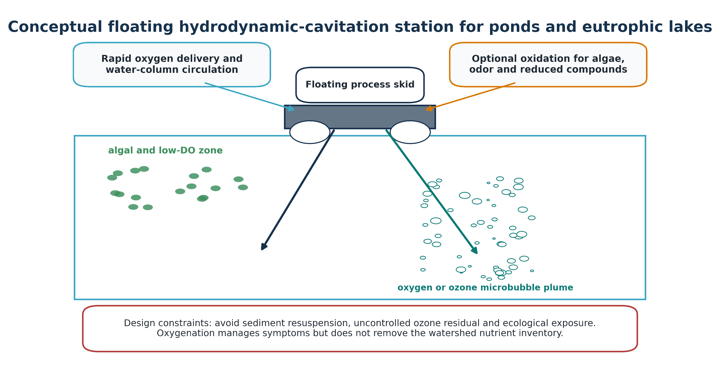
Figure 4.5. Conceptual floating hydrodynamic cavitation station for ponds and eutrophic lakes. [18,19].
4.6 Leachate Aeration, Oxidation, and Odor Control
Landfill leachate basins contain refractory organics, ammonia, reduced sulfur, dissolved metals, and volatile compounds. Aeration can oxidize reduced species and strip volatile gases, but it can also transfer odor and volatile compounds to the gas phase. Hydrodynamic cavitation is therefore better viewed as a pretreatment and gas liquid contactor than as an uncontained stripping method. The off gas stream requires downstream treatment, and foam control is normally necessary.
Hydrodynamic cavitation alone has generally produced modest changes in mature landfill leachate. Bis et al. increased the BOD5/COD biodegradability index from 0.046 to 0.056 after 30 passes, indicating transformation rather than complete treatment [20]. Hybrid oxidation produced stronger responses: HC with potassium ferrate removed 51.69% COD, 65.14% UV254, and 38.53% TOC under the reported optimum, while BOD5/COD increased from 0.362 to 0.61 [21]. Coagulation followed by HC/ClO2 achieved 83.58% COD removal in another study [22]. These results support cavitation as a reaction intensification stage before biological treatment, not as an uncontained atmospheric stripping process.
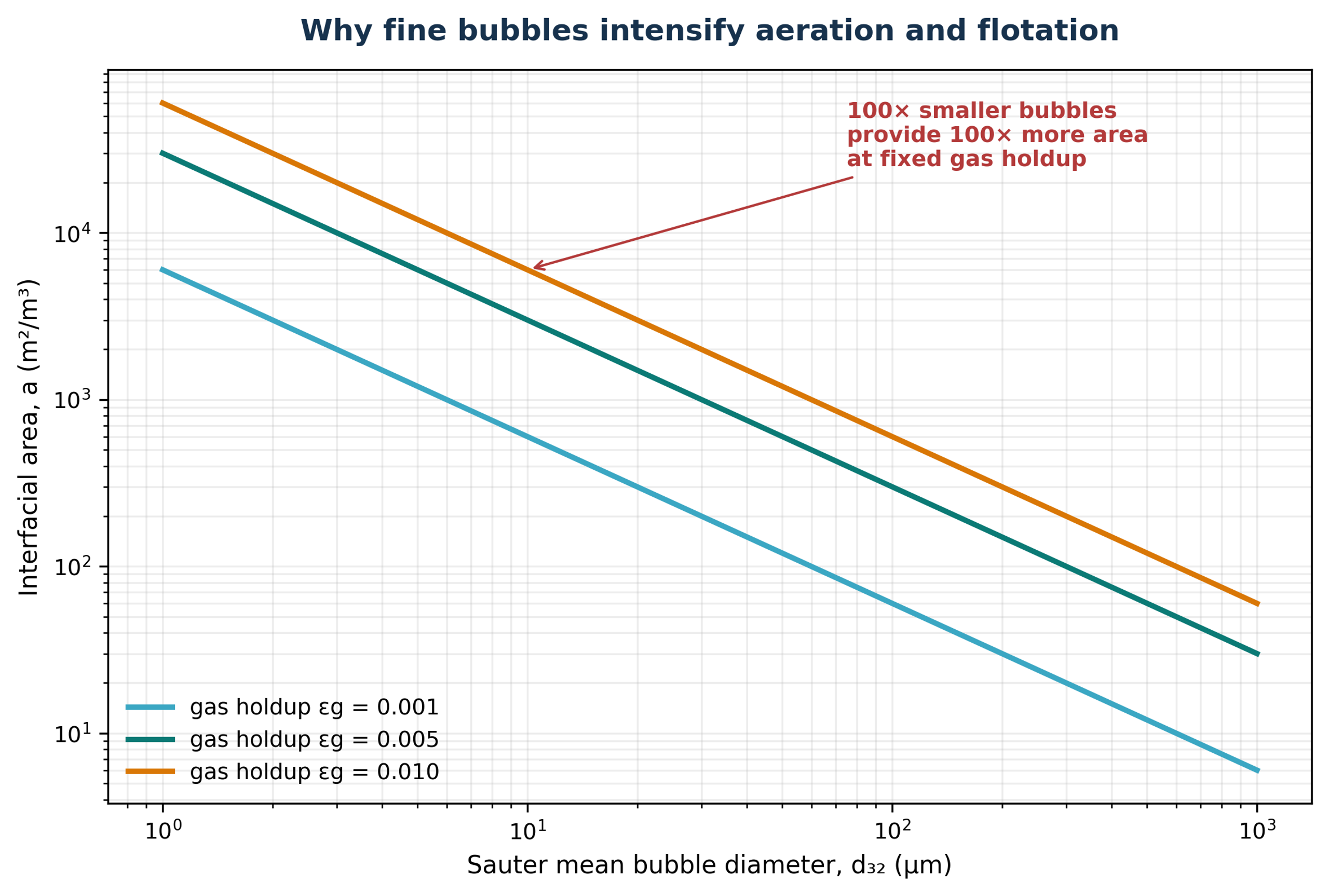
Figure 4.6. Why fine bubbles intensify aeration and flotation.
Table 4.1. Application specific design priorities for cavitation aeration
| Application | Primary objective | Critical measurements | Main failure modes |
|---|---|---|---|
| Activated sludge | Oxygen transfer and solids suspension | kLa or SOTR, SAE, DO profile, OUR, NH4 N, MLSS | Poor circulation, floc breakup, excessive energy, foam, inadequate anoxic zoning |
| CAF pretreatment | Bubble contaminant contact and float formation | Bubble size, recycle ratio, coagulant dose, surface loading, float solids | No flocculation, excessive turbulence in separator, weak skimming, recycle solids |
| Ponds and lakes | DO recovery, circulation, optional oxidation | Vertical DO/temperature, chlorophyll a, ozone residual, sediment turbidity | Sediment resuspension, ozone exposure, nutrient release, uneven circulation |
| Leachate basins | Pretreatment, oxidation, odor reduction | COD, BOD5/COD, ORP, NH3, H2S/VOC off gas, foam | Air emission, refractory residuals, corrosive gas, uncontrolled foam |
5 Flotation and Clarification
5.1 Bubble Particle Capture
Flotation recovery requires three probabilistic events: collision of a particle or droplet with a bubble, attachment after the intervening liquid film drains and ruptures, and retention of the aggregate against detachment forces. Hydrodynamic cavitation can contribute in two ways. It can produce a fine bubble population from dissolved gas or injected air, and it can nucleate bubbles directly on hydrophobic surfaces or within flocs. Surface nanobubbles then act as secondary collectors, increasing effective hydrophobicity and shortening induction time [23-26]. The overall collection efficiency or probability of particle capture () is governed by the collision, attachment, and detachment probabilities:
Pc is collision probability, Pa is attachment probability after collision, and Pd is detachment probability. Some literature uses different definitions, so the meaning of each term should be stated.
The phenomenological form for collision is:
This phenomenological form emphasizes that collision probability generally rises as particle diameter dp increases and bubble diameter db decreases; A and n depend on the flow regime.
Sb is bubble surface area flux and Jg is superficial gas velocity. It combines bubble size and gas rate into a useful flotation metric.
Stokes' law gives terminal rise velocity for a small isolated spherical bubble in the creeping flow regime. Larger, contaminated, or interacting bubbles require other drag correlations.
A first order flotation model relates recovery R to time t, ultimate recovery R∞, and apparent rate constant k.
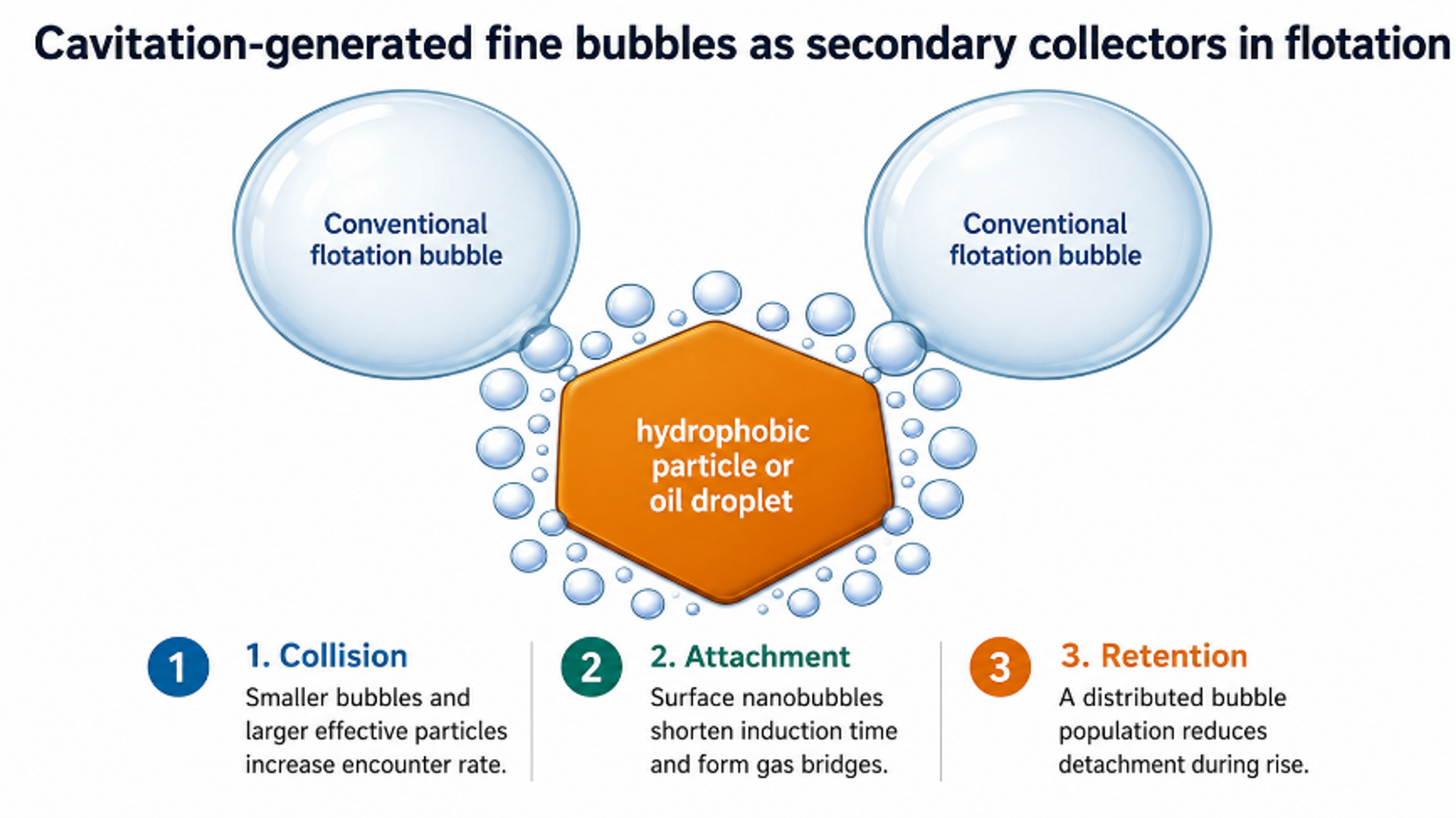
Figure 5.1. Cavitation generated fine bubbles as secondary collectors in flotation. [23-26].
5.2 Petrochemical and Refinery Wastewater
Refinery wastewater contains free oil, dispersed droplets, stable emulsions, suspended solids, corrosion products, and treatment chemicals. Free oil should be removed by gravity separators or hydrocyclones before flotation. Cavitation generated microbubbles are most useful for the remaining dispersed droplets and flocculated emulsion fragments. Bubble size should be comparable to or smaller than the target droplets to maximize encounter probability, while a coarser fraction provides buoyant lift.
Loraine and Chahine used vortex cavitating jet generators to produce a polydisperse bubble population from a few micrometres to approximately 300 µm and recover nearly neutrally buoyant crude oil droplets. The oil droplets alone rose at only 0.0147 to 0.16 mm/s in the reported 35 ppt tests; bubble oil mixtures rose at 0.3 to 1.6 mm/s, while clean water bubbles rose at 30 to 50 mm/s [27]. The mixed bubble distribution was beneficial because the smallest bubbles attached to droplets and the larger bubbles transported the complexes upward.
Independent dissolved air flotation research with microbubbles of 30-40 µm and nanobubbles of 150-350 nm showed 75% oil removal in saline water and 90% without salt under the reported nanobubble conditioning conditions [29]. A column flotation study using micro- and nanobubbles reduced residual oil to 4 mg/L in its taller column under selected conditions [30]. These results establish the importance of bubble size, salinity, emulsion chemistry, flocculation, and column hydraulics. They do not imply that cavitation alone breaks every stable refinery emulsion.
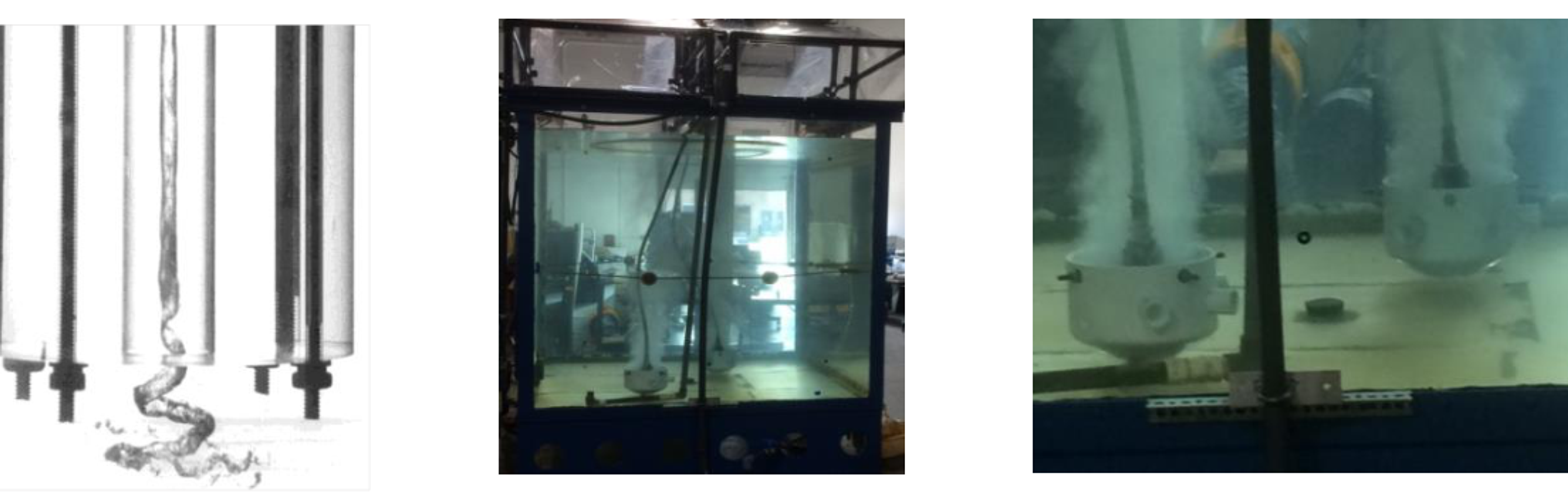
Figure 5.2. Vortex cavitation core, large test tank, and submerged cavitating bubble generators used in oil recovery experiments. [27].
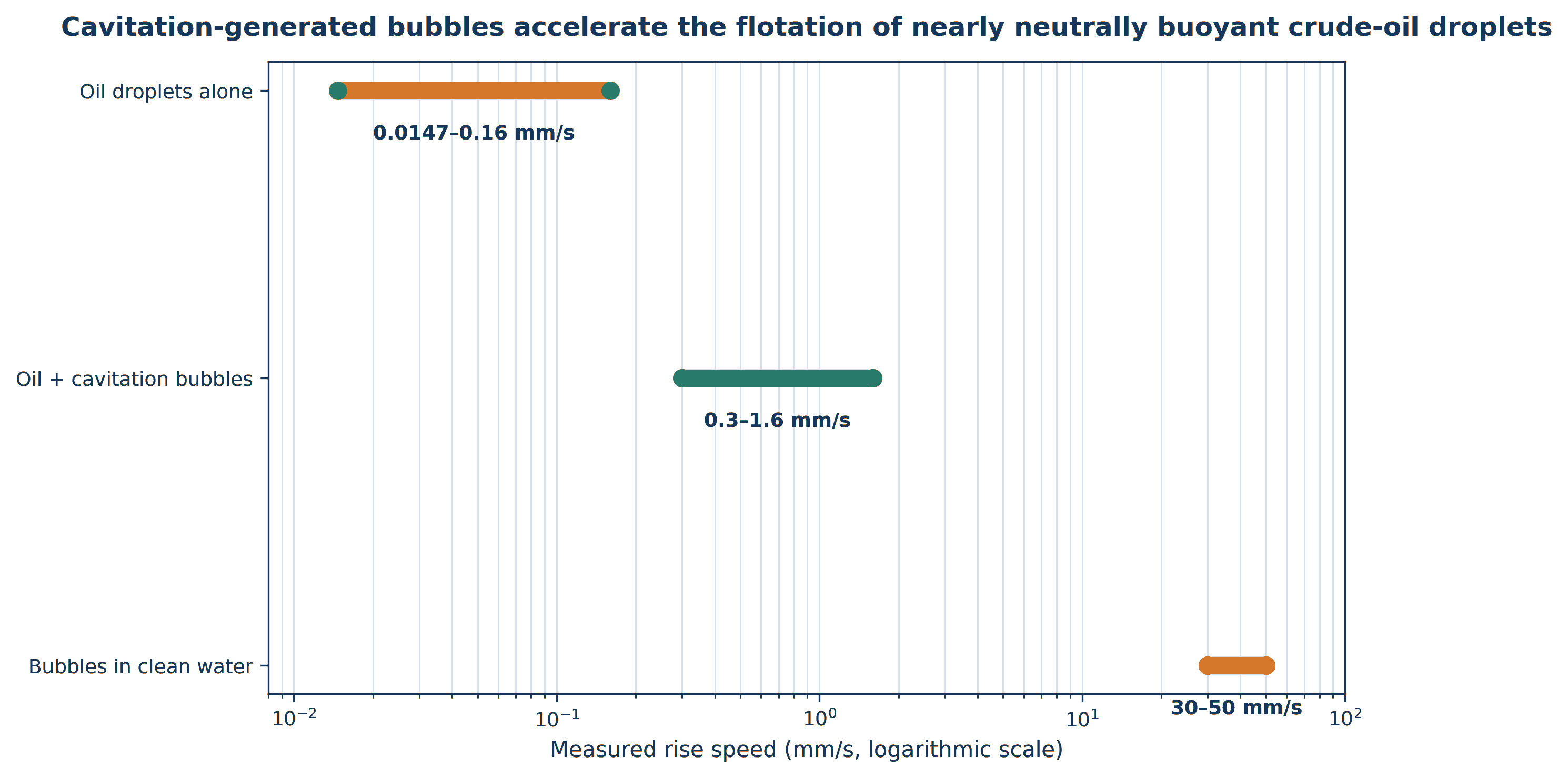
Figure 5.3. Cavitation generated bubbles accelerate the flotation of nearly neutrally buoyant crude oil droplets. [27].
5.3 Food Processing and Slaughterhouses
Food processing wastewater is frequently warm and contains fats, oils, grease, proteins, suspended tissue, starch, and cleaning chemicals. Temperature lowers water viscosity but may keep some fats liquid and emulsified. Equalization is required because pH and organic load change sharply during cleaning cycles. A practical flotation train uses coarse screening, equalization, pH adjustment, coagulation or emulsion breaking, flocculation, microbubble contact, float removal, and biological treatment.
At a 310 m³/d slaughterhouse plant, the first stage conventional DAF removed approximately 84% FOG and 72% suspended solids before biological treatment [28]. This evidence is not specific to hydrodynamic cavitation bubble generation, but it defines the pretreatment duty that a CAF system must equal or exceed. Cavitation can reduce the compressed air and saturation vessel requirements when self-aspiration is effective, yet the total process economics must include pump energy, coagulant demand, float handling, odor control, and cleaning of the aerator.
5.4 Pulp and Paper Mills
Whitewater contains recoverable fibers, fines, clay or calcium carbonate filler, sizing agents, dissolved and colloidal substances, and microorganisms. Flotation can return fibers to the process, reduce solids loading on savealls and biological treatment, and support water circuit closure. The fibers and fillers are often readily floatable after polymer conditioning, but aluminum salts, anionic trash, and variable furnish chemistry strongly affect performance.
Furukawa's dissolved air flotation study showed that pulp type, filler fraction, aluminum sulfate, and polyelectrolyte selection determine flotation velocity and clarity [31]. A long term industrial field trial in a mill using 100% recovered paper demonstrated that an optimized polyaluminum salt/polyamine treatment improved DAF removal under high contaminant load and permitted greater circuit closure [32]. Cavitation spargers can be inserted as the bubble generation stage, but the same furnish specific coagulation and retention chemistry remains necessary.
5.5 Tanneries and Textile Processing
Tannery wastewater can contain hair, flesh, protein, sulfide, chromium bearing solids, fat, and suspended lime. Textile wastewater contains dyes, surfactants, salts, fibers, and sizing chemicals. Flotation is most effective after the target is converted into a hydrophobic precipitate or floc. Sulfide and volatile compounds favor enclosed gas handling, while chromium bearing solids should be recovered rather than dispersed by aggressive aeration.
Dafnopatidou and Lazaridis reported dye removal above 97% from selected simulated and industrial textile effluents when dissolved air or dispersed air flotation was combined with appropriate collectors, flocculants, and polyelectrolytes [33]. The study also warned that full scale confirmation was needed. A cavitation contactor may reduce bubble size and improve contacting, but it cannot substitute for charge neutralization and selective chemistry.
Table 5.1. Cavitation flotation applications and pretreatment requirements
| Sector and target | Typical conditioning before bubble contact | Primary separator duty | Important caution |
|---|---|---|---|
| Refinery: dispersed crude, fuels, free oil residual | Gravity free oil removal, emulsion breaker, pH and polymer as needed | Lift droplet floc aggregates; skim oil rich float | Stable surfactant emulsions may require substantial chemistry |
| Food/slaughterhouse: FOG, blood, proteins | Screening, equalization, pH control, coagulant/polymer | Reduce FOG, TSS, BOD/COD load before biology | Odor, warm emulsions and variable cleaning chemistry |
| Pulp and paper fibers, fines, filler | Furnish specific cationic polymer or coagulant | Recover fiber and clarify whitewater for reuse | Aluminum salts and dissolved/colloidal substances alter response |
| Tannery: hair, protein, chromium solids | Segregation, sulfide control, precipitation and flocculation | Remove floatable solids and precipitates | Do not strip untreated sulfide; segregate chromium bearing sludge |
| Textile: dye aggregates and fibers | Collector, surfactant, electrolyte and polyelectrolyte optimization | Float dye flocs and suspended fibers | Residual color and salinity may still require oxidation or membranes |
Table 5.2. Representative bubble size regimes and their flotation roles
| Nominal size range | Primary role | Advantages | Limitations |
|---|---|---|---|
| <1 µm, often termed nanobubbles | Surface activation and secondary collection | Long residence, nucleation on hydrophobic surfaces, reduced induction time | Measurement uncertainty; limited direct buoyancy; stability depends on chemistry |
| 1-20 µm | Attachment to fine particles and droplets | Very high interfacial area and encounter frequency | Slow rise and possible loss with clarified water |
| 20-100 µm | Conventional DAF/CAF lifting bubbles | Good compromise between area and rise velocity | Coalescence and dissolution depend on saturation and surfactants |
| 100-300 µm | Bulk lift and circulation in polydisperse systems | Higher rise velocity; can entrain fine bubble particle complexes | Lower area per gas volume; greater detachment risk for weak aggregates |
5.6 Fine Mineral Flotation and Dual Bubble Systems
Fine mineral particles are difficult to recover because their inertia is too small to produce frequent collisions with conventional millimeter size bubbles. Under otherwise similar hydrodynamic conditions, collision probability scales approximately with the square of the particle to bubble diameter ratio. Reducing bubble size and forming selective particle aggregates are therefore complementary strategies. Hydrodynamic cavitation can contribute both effects by generating microbubbles and by promoting bubble attachment to hydrophobic surfaces [25,26,56].
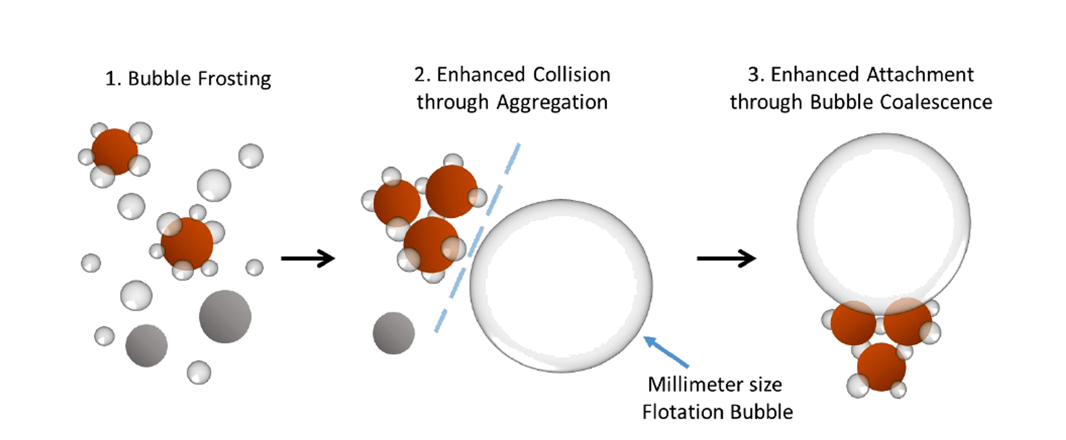
Figure 5.4. Mechanism proposed for hydrodynamic cavitation enhanced fine particle flotation: bubble frosting, aggregation, and microbubble assisted attachment. [56].
The University of Alberta thesis separates the enhancement into three steps. First, cavitation microbubbles preferentially nucleate or remain on hydrophobic particle surfaces, a phenomenon described as bubble frosting. Second, surface microbubbles bridge particles and increase their apparent size, raising collision probability. Third, a conventional flotation bubble attaches more readily to a microbubble covered aggregate because the intervening liquid film drains rapidly and local coalescence provides an attachment pathway. The measured benefit was much stronger for hydrophobized silica than for hydrophilic silica, indicating that cavitation can improve selectivity as well as recovery [56].
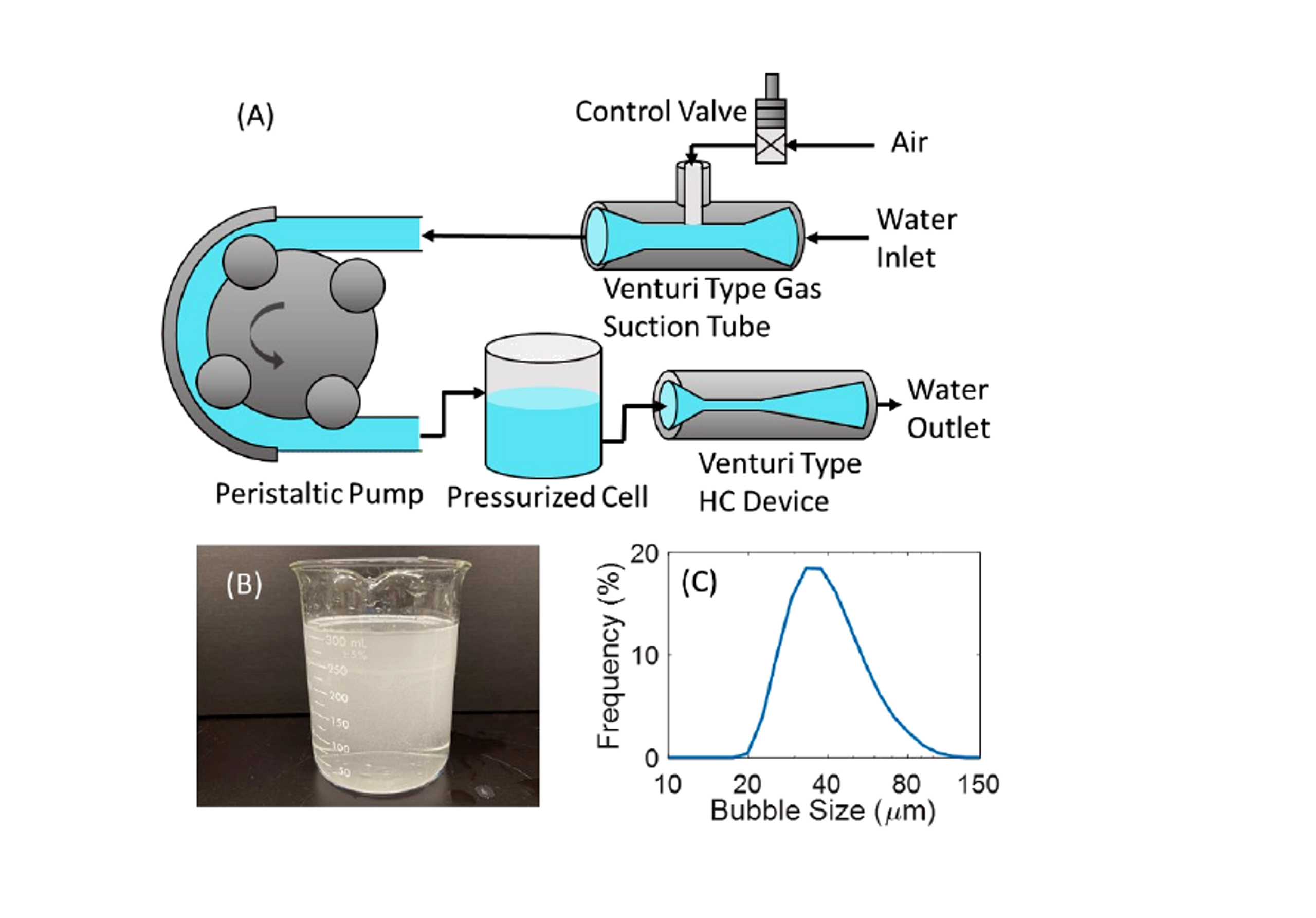
Figure 5.5. Auto gas suction Venturi loop, visible microbubble dispersion, and measured bubble size distribution. [56].
Gas injection location is a decisive design variable. Injection upstream of a Venturi may fragment conventional bubbles but can suppress the formation of a distinct cavitation microbubble population. Injection downstream can preserve both populations and create a dual bubble system. In the reported molybdenite and silica tests, upstream injection reduced selectivity through entrainment, whereas downstream injection allowed recovery and concentrate grade to be balanced by gas rate and injection distance [56]. Commercial cavitation tube spargers apply the same principle in column flotation and feed pre aeration circuits, where recycle slurry, process air, and a cavitating restriction are combined to create a dense fine bubble plume [25,26,67].
5.7 Integrated Coagulation and Flotation for Natural Organic Matter
Hydrodynamic cavitation can integrate rapid coagulant dispersion and microbubble generation in a compact treatment step. Pagan et al. injected ferric chloride at the throat of a continuous flow Venturi system and floated the destabilized humic substances. Five divergent angles were compared while throat diameter and converging geometry were held constant [57].
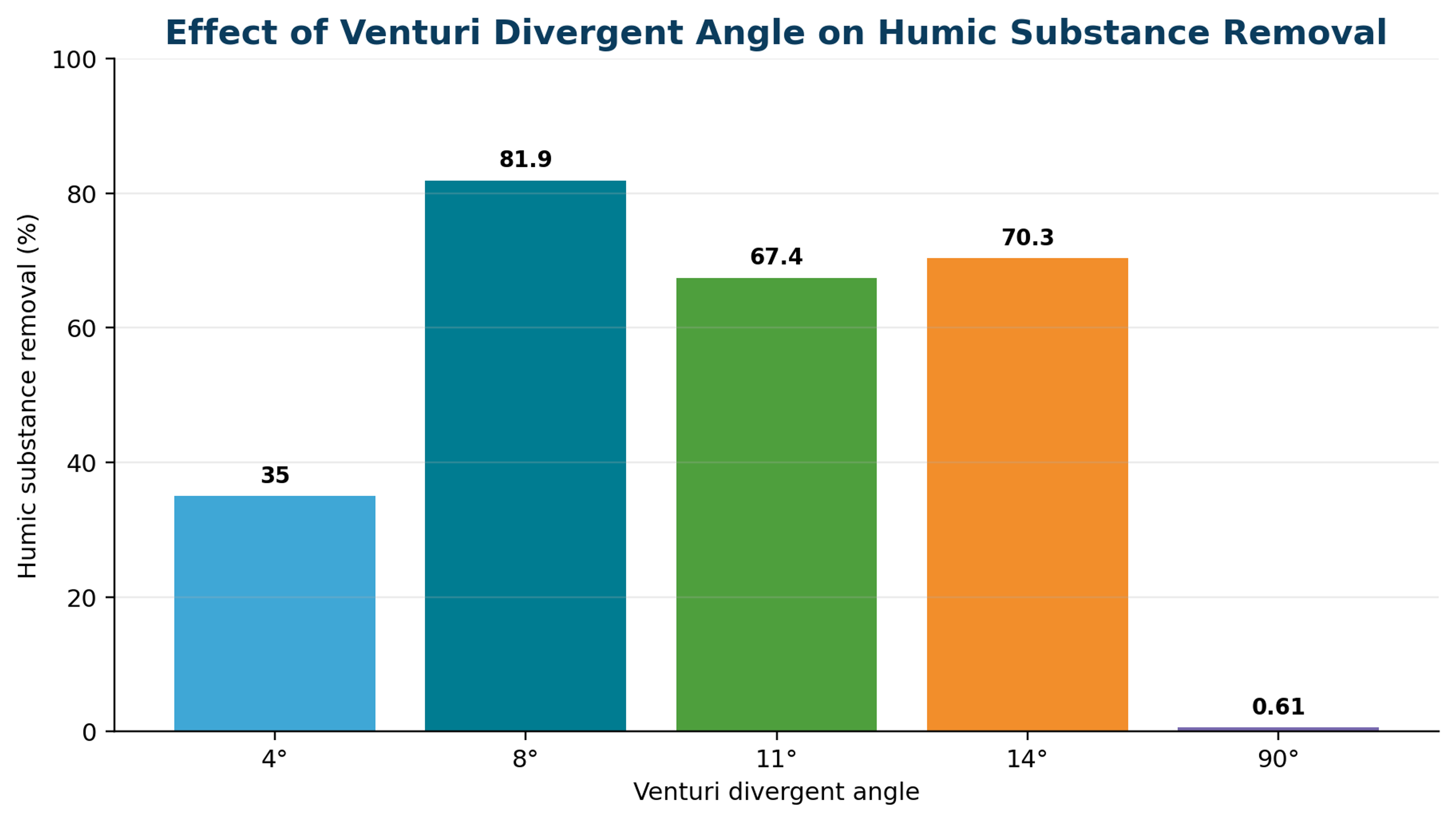
Figure 5.6. Effect of Venturi divergent angle on humic substance removal. [57].
The 8° divergent angle produced the best reported removal, 81.9%, because it combined stable microbubble generation with effective pressure recovery and rapid coagulant distribution. Comparable performance in the reference dissolved air flotation apparatus required at least 30% saturated recycle water, whereas the cavitation system operated continuously without an external saturation vessel. The result shows that geometry controls not only cavitation intensity but also bubble residence, coagulant mixing, and the hydrodynamic pathway to separation [57].
is the humic substance removal efficiency, C₀ is the initial concentration, and Cₜ is the concentration after the specified coagulation and flotation period.
Translation to drinking water requires additional validation. Humic acid concentration, molecular character, alkalinity, pH, coagulant dose, residual iron, floc strength, downstream filtration, disinfection byproduct formation potential, and sludge handling must all be evaluated. The cavitation unit should be considered an integrated contactor whose success depends on the complete solids separation train, not on removal measured immediately after the Venturi alone [57].
6 Degassing and Gas Stripping
6.1 Two Step Mechanism: Nucleation and Disengagement
Degassing requires two distinct operations. First, the liquid must become supersaturated with respect to the local pressure so that dissolved gas forms bubbles or expands existing nuclei. Second, the bubbles must coalesce, rise, or be separated before they redissolve during pressure recovery. A cavitation device can perform the first operation very effectively but may fail as a complete degasser if the outlet immediately repressurizes the bubble laden liquid without a venting vessel [14,17,34].
This form of Henry's law uses a concentration based Henry constant Hi. Other conventions use the reciprocal constant; the convention and temperature must be stated.
For stripping, bulk concentration exceeds the equilibrium concentration associated with the gas phase partial pressure.
For an ideal first order contactor, ηstrip is fractional removal and τ is gas liquid contact time. Actual systems may be limited by bubble disengagement and back mixing.
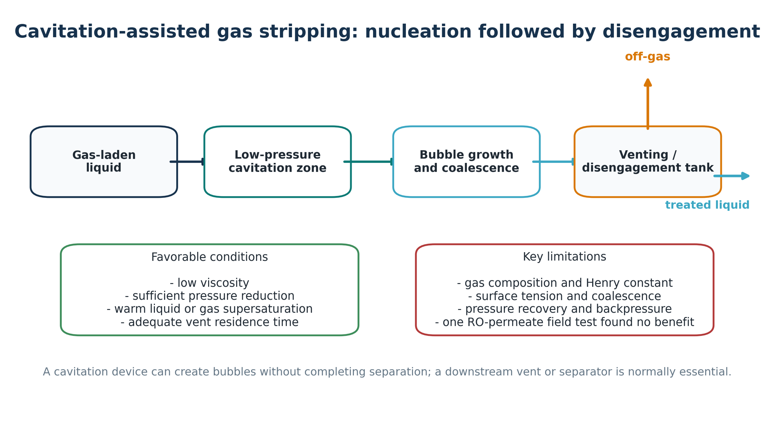
Figure 6.1. Cavitation assisted gas stripping: nucleation followed by disengagement. [70].
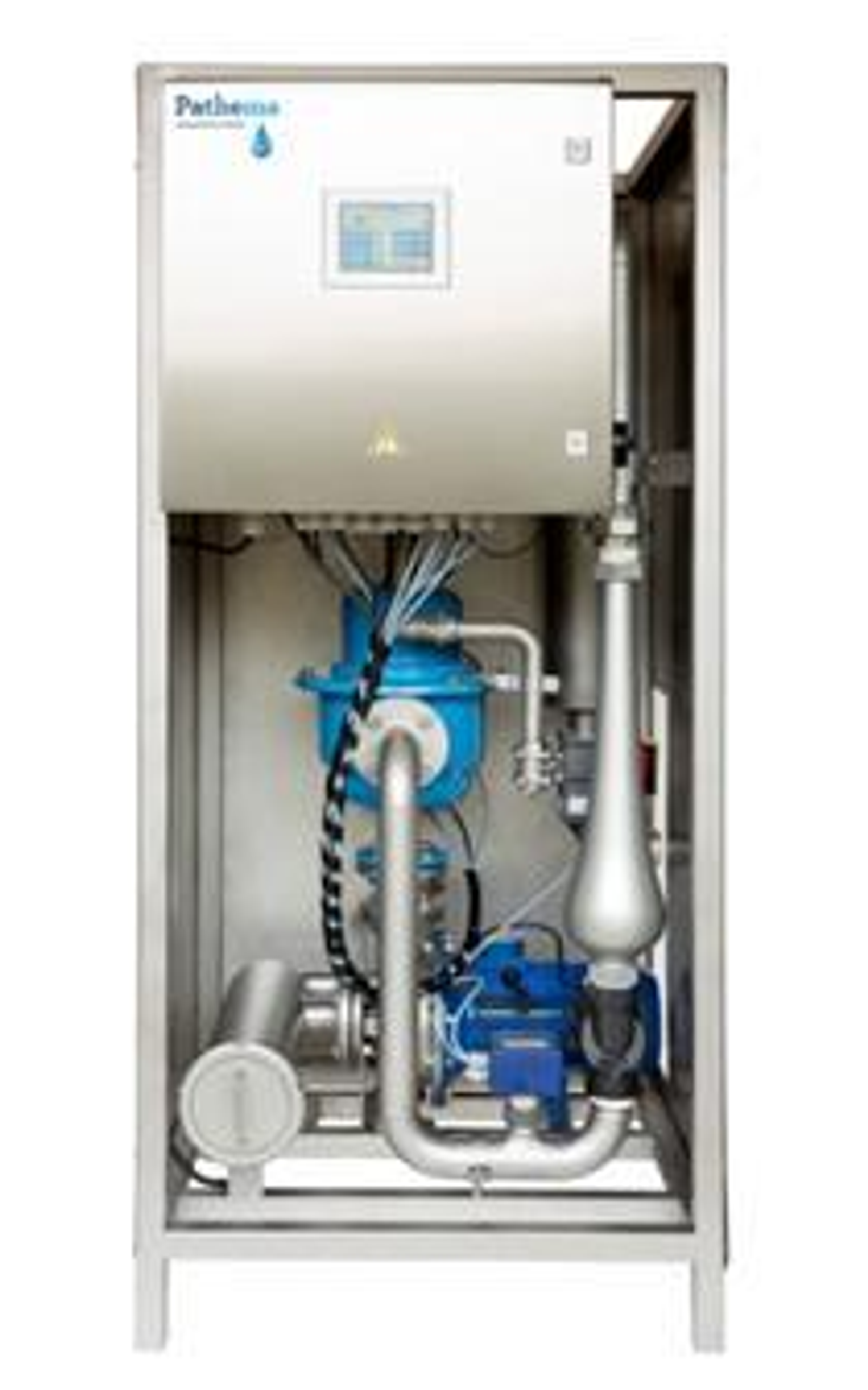
Figure 6.2. Packaged vortex treatment skid used in industrial degassing and cooling water trials. [14].
6.2 Demonstrated Uses and Limitations
The ISPT project compared three end uses. Low viscosity dairy liquids deaerated faster after vortex treatment than by spontaneous holding tank deaeration, although a small venting tank was still required. In an evaporative condenser, the treatment successfully supported chemical free scale and corrosion control. In contrast, processing reverse osmosis permeate did not reduce dissolved gases and was judged to add no value in that application [14]. These contrasting results are instructive: a low pressure zone is not sufficient if the dissolved gas loading, gas speciation, pressure recovery, temperature, or downstream separator does not create a net removal path.
Potential stripping targets include carbon dioxide, oxygen, hydrogen sulfide, methane, ammonia under favorable pH, and volatile organic compounds. Each requires a gas specific mass balance and off gas treatment. Removing oxygen may reduce oxidation and corrosion in some closed processes, but aeration may be required elsewhere. Carbon dioxide removal raises pH and can intentionally precipitate carbonate hardness but may also cause uncontrolled scaling downstream. Hydrogen sulfide and VOC stripping require enclosure, ventilation, explosion assessment, and air pollution control. The choice between cavitation, vacuum degassing, membrane contactors, steam stripping, inert gas stripping, or thermal deaeration should be based on the required residual concentration and the value of integrating the hydraulic device with another process duty.
Table 6.1. Cavitation assisted degassing applications
| Liquid and target gas | Potential benefit | Required downstream equipment | Evidence or risk |
|---|---|---|---|
| Low viscosity food liquids; entrained air | Reduced holding time and air related process defects | Small vent or disengagement tank | Positive industrial experiment [14] |
| Cooling water; CO2 | pH shift and bulk carbonate precipitation | Side stream solids separator and basin venting | Field use, but chemistry must be controlled [7–14] |
| RO permeate; dissolved air/CO2 | Potential reduction in chemical demand | Vent, vacuum or sweep gas if pressure recovery is insufficient | Uploaded field experiment found no removal [14] |
| Closed process liquid; O2 | Reduced oxidation or corrosion | Gas tight separator and oxygen control | Application specific; avoid microbial anaerobiosis |
| Leachate or wastewater; H2S/VOCs | Odor and toxicity reduction | Enclosed off gas collection and treatment | Uncontrolled stripping transfers pollution to air |
6.3 Engineered Cavitation Degassers and Bubble Coalescers
Patented cavitation degassers illustrate why nucleation and separation should be designed as distinct hydraulic functions. The Soviet apparatus SU 1258460 A1 places a cavitation element in a working chamber, draws gas through a vacuum outlet, and uses a diffuser and conical recovery chamber to enlarge the gas liquid interface and discharge liberated gas. The stated design objective was higher throughput with lower specific energy [60].
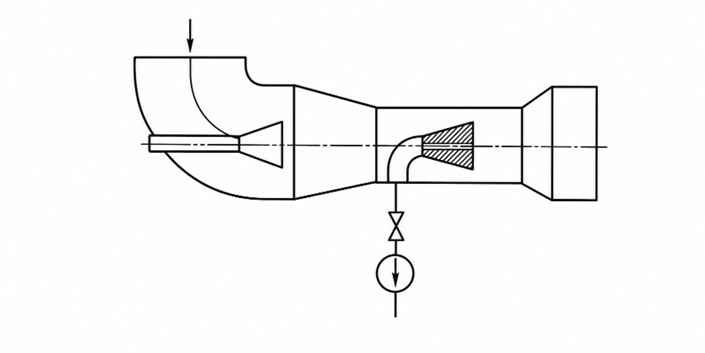
Figure 6.3. Hydrodynamic liquid degassing apparatus with a cavitation element, vacuum gas withdrawal, and diffuser [60].
A later United States patent by Kozyuk uses a cavitating restriction to nucleate dissolved gases, followed by a sequence of annular chambers, turns, and velocity reductions that promote bubble coalescence before the liquid exits. Small bubbles are deliberately converted into fewer, larger bubbles because larger bubbles separate more readily and are less likely to be carried into downstream equipment [61].
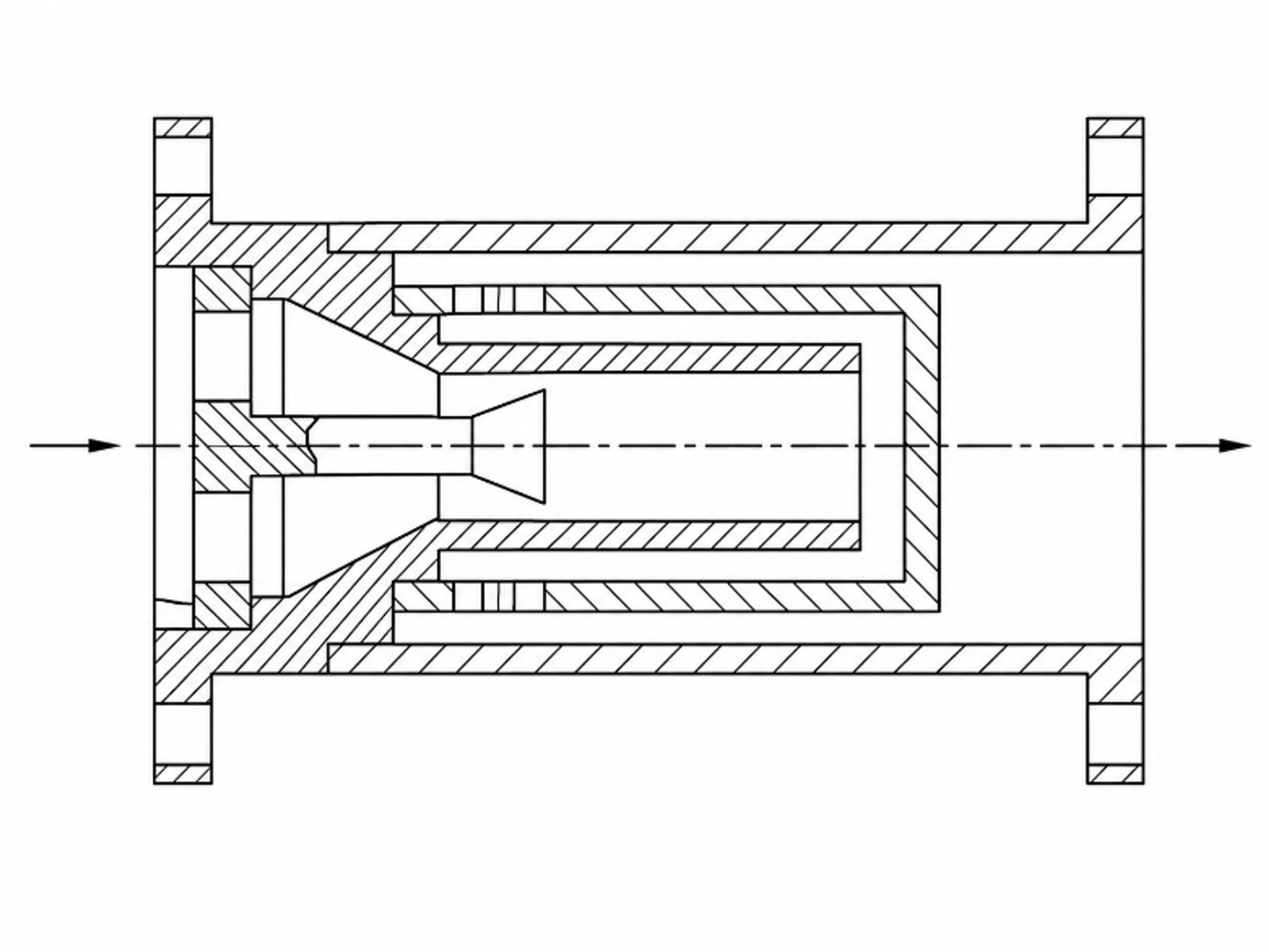
Figure 6.4. Cavitation and staged coalescence geometry for liquid degassing. [61].
Table 6.2. Functional comparison of two cavitation degasser concepts
| Design function | SU 1258460 A1 | U.S. Patent 10,159,915 B2 |
|---|---|---|
| Nucleation | Cavitation element in the working chamber | One or more local restrictions create cavities and release dissolved gases. |
| Gas growth | Gas enriched cavities expand through the diffuser and low pressure zone | Repeated changes in velocity and direction provide time for dissolved gas to enter cavities. |
| Coalescence | Conical recovery chamber and developed interface | Successive annular chambers reduce velocity and merge small bubbles. |
| Separation | Vacuum gas outlet and downstream discharge | Coalesced bubbles leave the liquid through a downstream separator or vented vessel. |
| Primary design risk | Insufficient venting or gas entrainment at high throughput | Re dissolution if pressure recovers before bubbles are physically separated. |
A complete degassing skid therefore requires a pressure controlled cavitation stage, a low velocity coalescence volume, a vent or vacuum connection, mist elimination where volatile liquids are processed, and controls that prevent air ingress or unsafe gas accumulation. Gas composition, flash point, toxicity, oxygen sensitivity, foam, and condensable vapor loading determine the required vent treatment. Performance should be reported as residual dissolved gas at a stated temperature and pressure, together with electrical energy per treated volume and the fraction of gas actually captured by the vent system.
7 Microalgae Lysis and Biomass Valorization
7.1 Role in Biorefineries and Cell Disruption
Microalgae and wet biomass contain proteins, lipids, pigments, carbohydrates, minerals, and specialized metabolites that can be recovered only after the surrounding cellular or plant structure is opened. Bead milling, high pressure homogenization, drying, solvent extraction, and enzymatic treatment can be effective, but energy demand and downstream separation often dominate process economics. Hydrodynamic cavitation provides a continuous wet route in which pressure pulses, shear, microjets, turbulence, and repeated wetting expose intracellular material without placing an acoustic transducer inside the vessel [53-55].
The process objective must be stated precisely. Complete lysis may be appropriate before low value lipid recovery, whereas selective permeabilization is preferable when proteins, pigments, antioxidants, or volatile compounds must retain functionality. Excessive cavitation can heat the slurry, oxidize unsaturated lipids, fragment target molecules, produce stable fines that are difficult to separate, or consume energy after the extraction plateau has been reached. A successful process therefore maximizes recovered product per unit electrical energy rather than maximizing noise, pressure drop, or visible vapor volume.
Eₛ is the specific electrical energy supplied to the cavitation loop, Pₑₗ is measured electrical power, t is treatment time, and is dry biomass mass. Reporting energy only per unit liquid volume can obscure the effect of slurry solids concentration.
is dry extract yield, is the recovered dry product mass, and mdry is the dry feed mass. Product purity and retained biological activity must be reported with yield.
7.2 Hydraulic Characterization and the Lysis Threshold
A low cavitation number does not by itself guarantee cell rupture. Bubble population, maximum cavity size, collapse location, solids concentration, liquid viscosity, dissolved gas, number of passes, and the mechanical strength of the target organism all matter. Small orifices create high throat velocity and low local pressure but may generate cavities too small to deliver sufficient collapse energy to a robust cell. Larger openings allow larger cavities but may not reach the required pressure depression unless pump capacity and downstream pressure are adjusted [53].
Hydraulic characterization should include upstream and downstream pressure, actual throat velocity, flow rate, liquid temperature, dissolved gas, high speed visualization or an acoustic indicator of collapse, and energy measured at the motor. For a recirculating batch, flow turnovers provide a better comparison than minutes because the same time can represent very different exposure when flow or vessel volume changes. Sampling should distinguish intact cells, reversibly permeabilized cells, fragmented cells, and dissolved product.
DL is the measured cell disruption fraction, is the number of cells meeting a defined damage criterion, and is the number evaluated. The criterion may be microscopy, dye uptake, released protein, chlorophyll, lipid, or another validated analytical response.
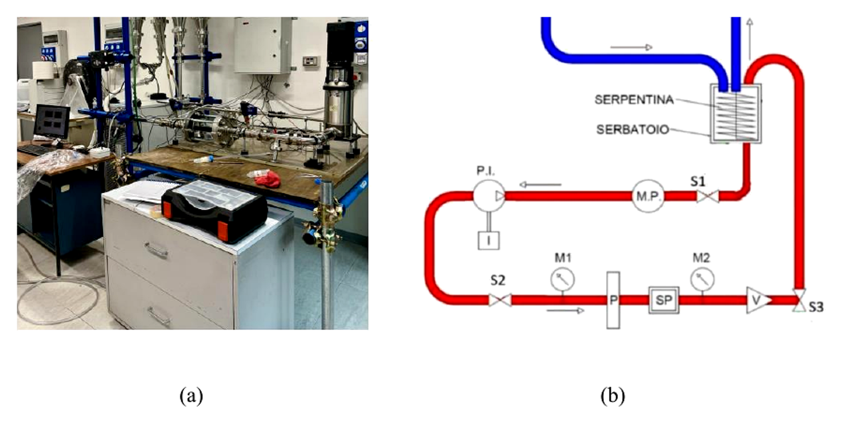
Figure 7.1. Experimental hydraulic loop and schematic used for microalgae cavitation tests. [53].
7.3 Evidence from Galdieria sulphuraria
The Politecnico di Torino study evaluated Galdieria sulphuraria in a stainless steel loop fitted with interchangeable 2, 3, 4.5, and 6 mm orifice plates. The 2 mm plate produced the lowest cavitation number because it generated the greatest velocity and pressure differential. High speed images nevertheless showed comparatively small cavities. Larger openings produced larger vapor structures but did not achieve equally low cavitation numbers with the available pump [53].
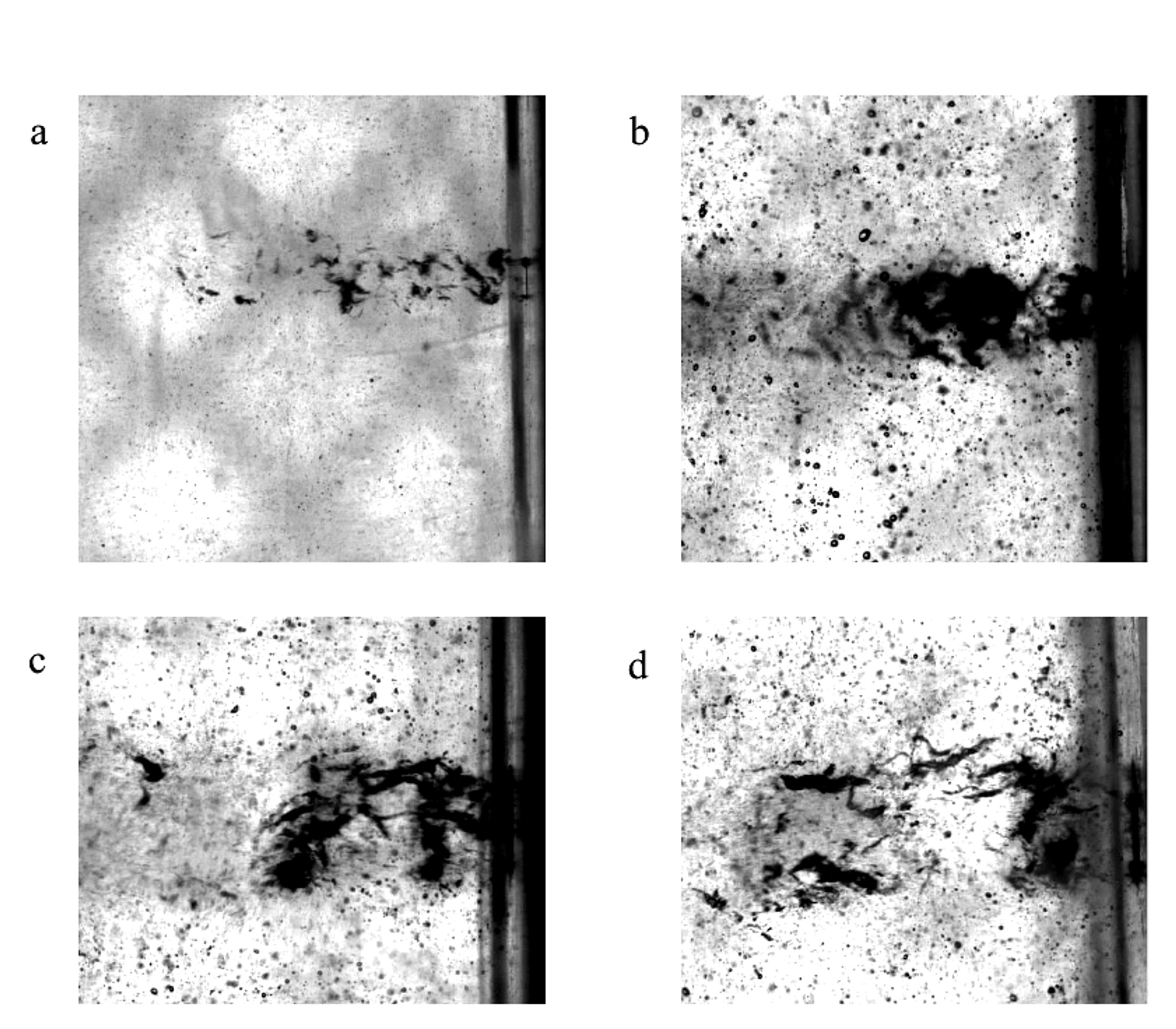
Figure 7.2. High speed views of cavitation structures produced by different orifice diameters in the microalgae test loop [53].
No effective rupture of the robust G. sulphuraria cell wall was demonstrated under the tested operating window. This negative result is important because it shows that intense looking cavitation and a low calculated cavitation number are not sufficient acceptance criteria. The reactor must simultaneously provide a suitable cavity size distribution, collapse intensity, exposure frequency, and proximity between collapsing cavities and cells. Naghashzargar therefore recommends a revised reactor and pumping configuration capable of combining low cavitation number with larger bubble implosions [53].
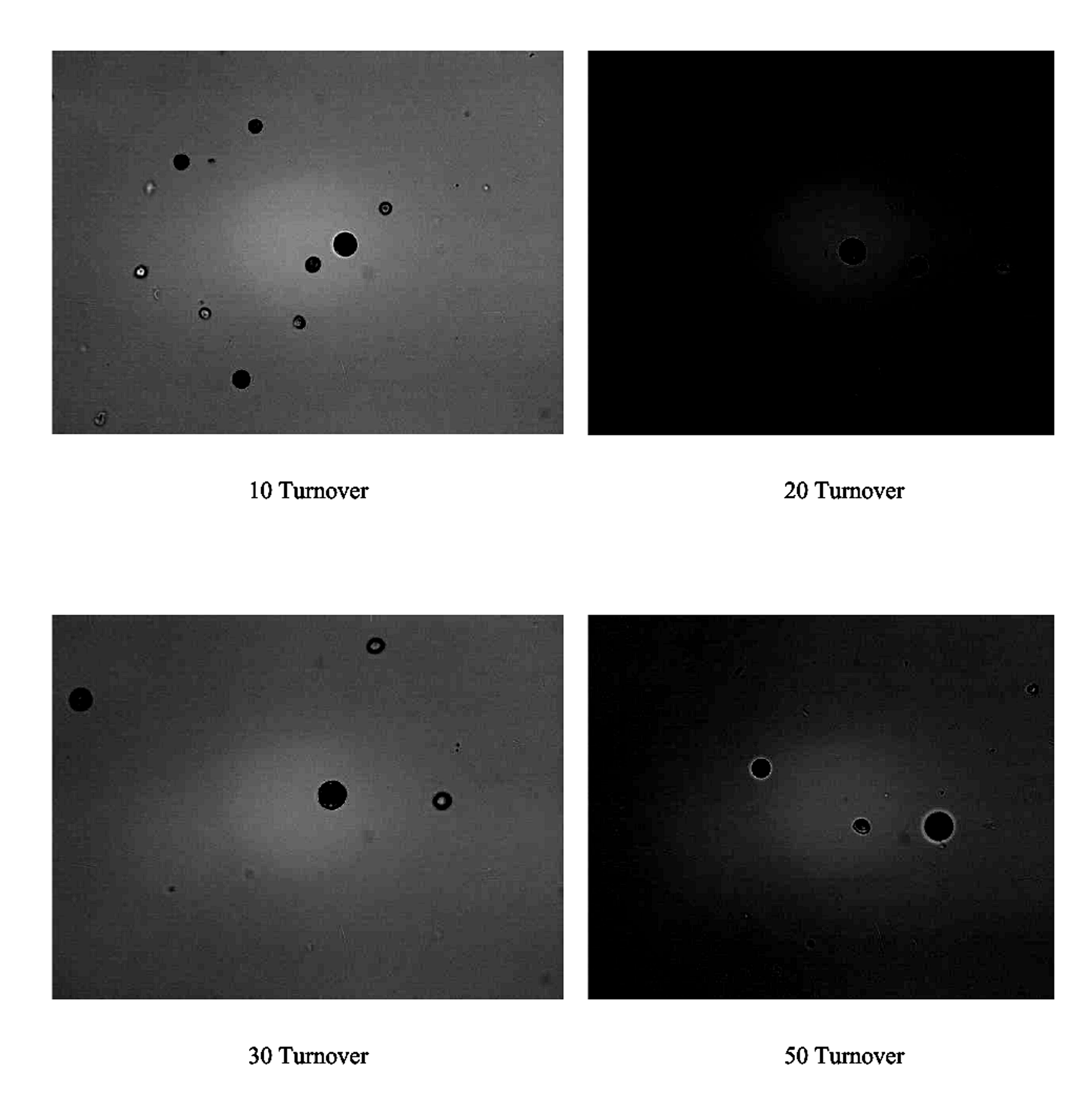
Figure 7.3. Bright field images after 10, 20, 30, and 50 flow turnovers. The study did not establish effective lysis in the tested window. [53].
For process development, a negative lysis result should trigger a mechanistic redesign rather than an arbitrary increase in pass count. Options include staged restrictions, a Venturi with a longer controlled cavity, gas dosing to modify nuclei, a rotor stator stage for repeated near wall collapse, increased solids concentration to reduce downstream water removal, and temperature control to protect target compounds. Each modification should be evaluated against both disruption yield and specific energy.
7.4 Plant Extraction and Circular Biorefineries
Hydrodynamic cavitation has also been used to extract polyphenols, pectin, terpenes, lipids, proteins, and other compounds from plant and algal matrices. In these systems, cell wall rupture and particle attrition increase accessible surface area while turbulence reduces the external mass transfer boundary layer. Static devices are simple but can clog when fibrous solids accumulate; rotor stator devices tolerate higher solids and provide repeated mechanical action at lower feed pressure [54,55].
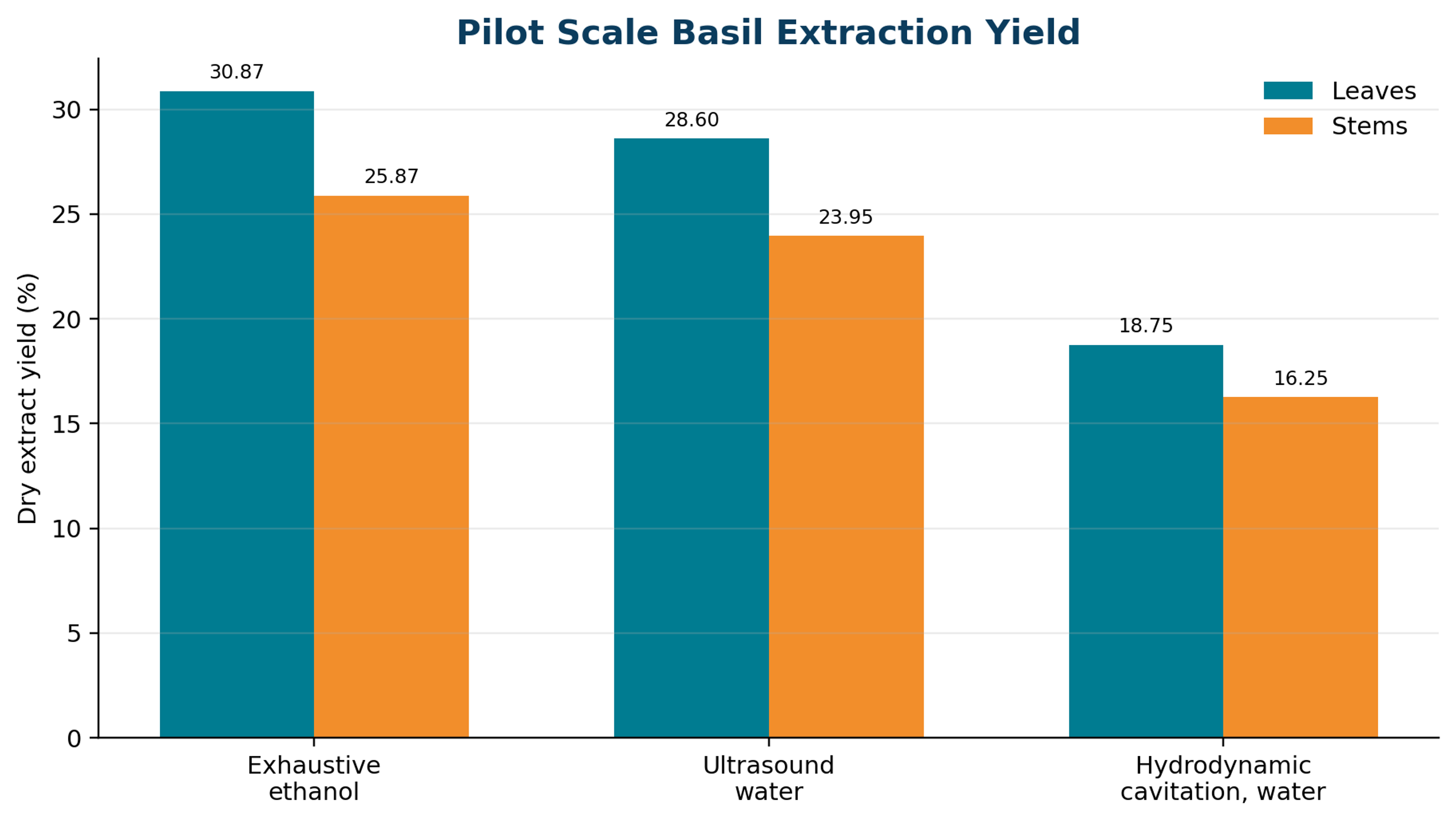
Figure 7.4. Pilot scale basil extraction yields reported for exhaustive ethanol, ultrasound assisted water extraction, and hydrodynamic cavitation water extraction. [54].
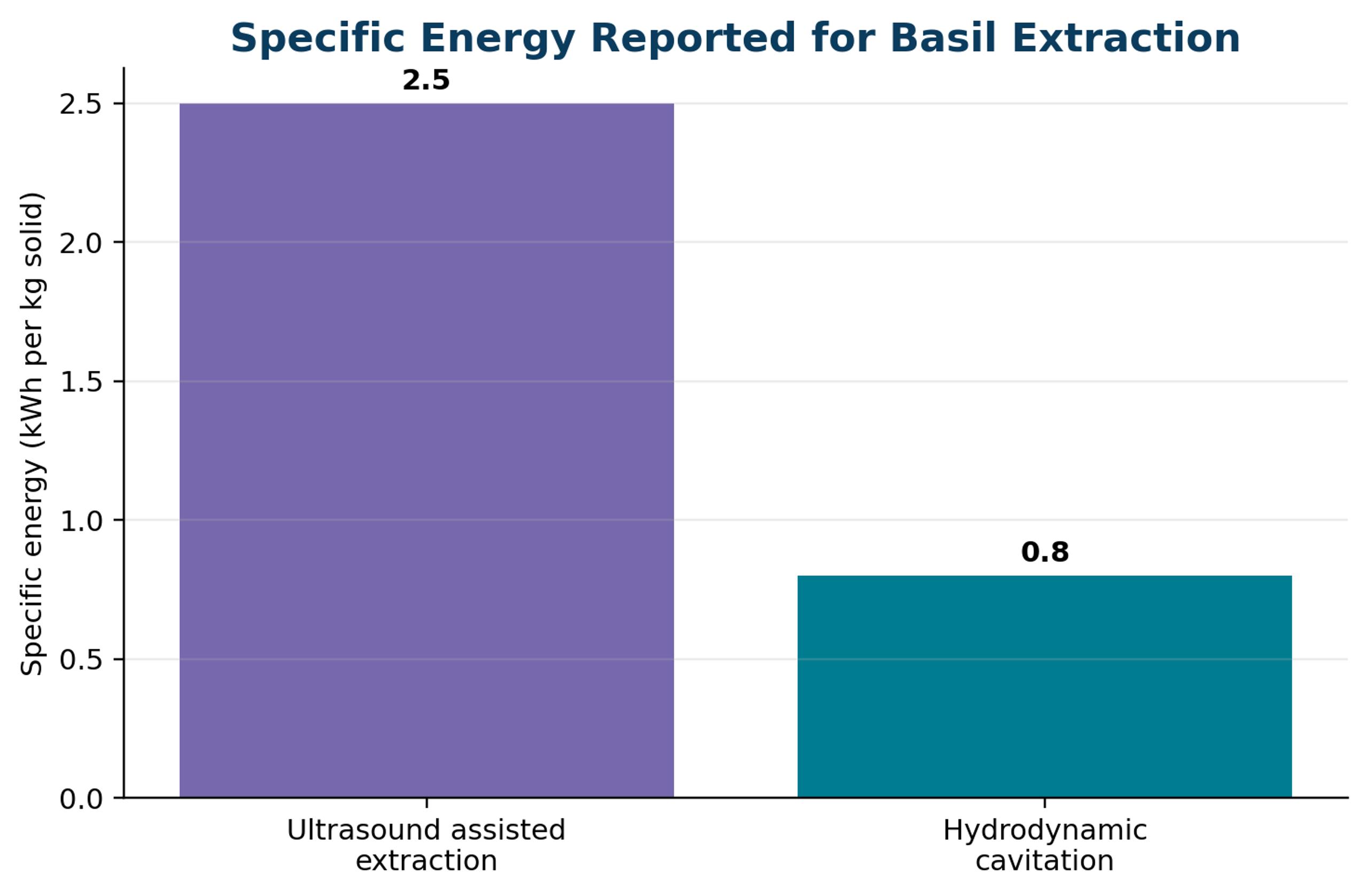
Figure 7.5. Specific energy reported for ultrasound assisted and hydrodynamic cavitation extraction of basil. [54].
In the basil case study reviewed by Wu and coworkers, exhaustive ethanol extraction gave the highest dry yield, while water based hydrodynamic cavitation gave lower yield than ultrasound. The cavitation route nevertheless required about 0.8 kWh per kilogram of solid compared with about 2.5 kWh per kilogram for ultrasound. The comparison illustrates that yield, solvent safety, extraction selectivity, energy, and downstream concentration must be evaluated together. A lower crude yield can be preferable when the desired compound is concentrated, water is the only solvent, and the extract requires less purification [54].
The review by Meneguzzo and coworkers emphasizes pilot scale water only operation, high solids loading, short residence time, and low water to biomass ratio. In many practical extraction trains, evaporation or drying consumes more energy than cavitation. Hydrodynamic cavitation may also form stable pectin, flavonoid, and terpene phytocomplexes and may influence protein polyphenol association, which can change apparent solubility, bioaccessibility, and ingredient functionality. These product effects require compositional, toxicological, and shelf life validation rather than extraction yield alone [55].
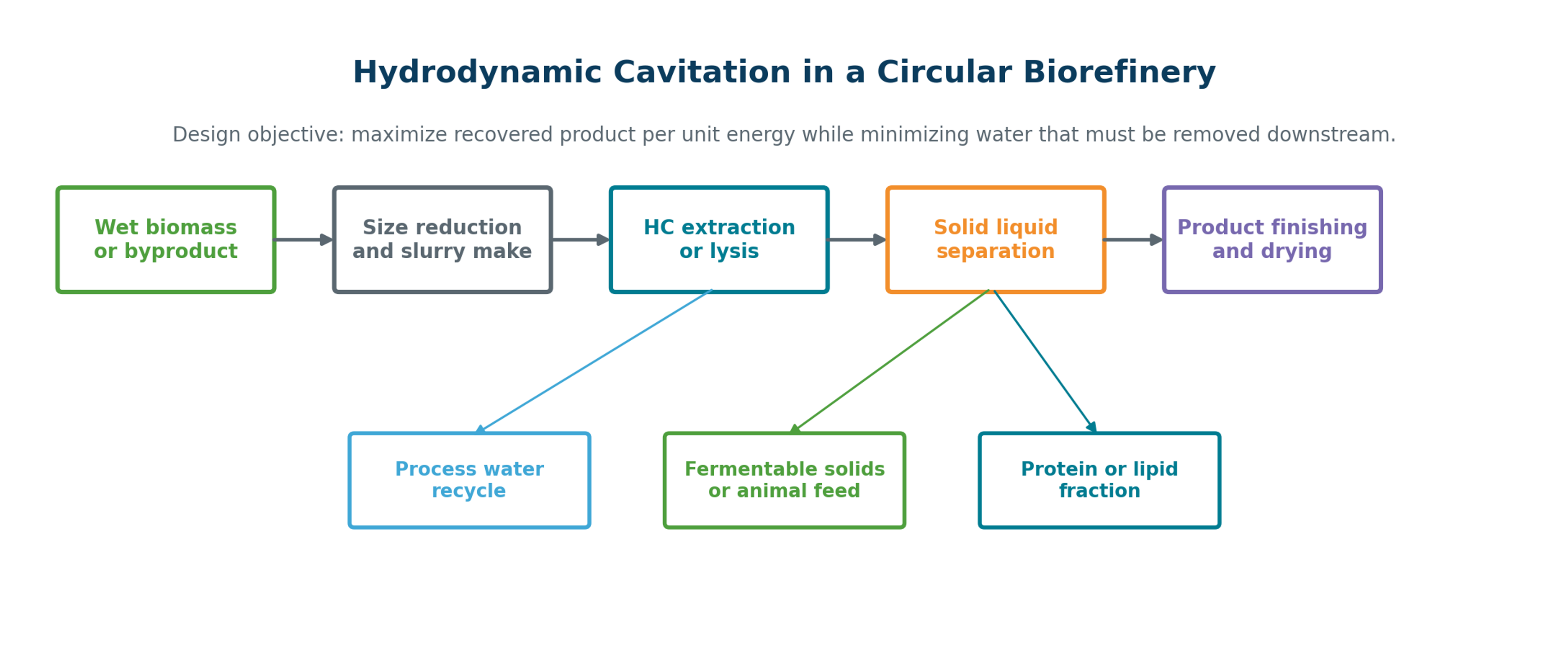
Figure 7.6. Integration of hydrodynamic cavitation into a circular biorefinery. [54,55].
7.5 Scale Up, Product Quality, and Process Integration
Scale up should preserve the local hydraulic event and the distribution of exposure while increasing throughput. Useful similarity variables include throat velocity, cavitation number calculated with stated pressure locations, Reynolds number, gas fraction, solids concentration, characteristic gap or throat geometry, and the ratio of loop volume to flow. Equal pressure drop does not guarantee equal treatment because cavity residence and collapse location change with scale.
A pilot program should close the mass balance around dry feed, clarified extract, residual solids, dissolved product, and cleaning losses. Product analysis should include target compound recovery, degradation markers, oxidation, molecular weight distribution where relevant, microbial status, color, aroma, functionality, and storage stability. Fouling and clean in place behavior must be evaluated with realistic biomass because a reactor that performs well in dilute laboratory suspensions may fail at industrial solids loading.
Table 7.1. Design priorities for biomass lysis and extraction
| Process objective | Primary response | Critical controls | Typical failure mode |
|---|---|---|---|
| Microalgae lipid recovery | Released lipid or extractable lipid fraction | Species, cell wall strength, solids loading, passes, temperature | High energy with incomplete rupture or oxidation of unsaturated lipids. |
| Protein recovery | Soluble protein and retained functionality | pH, temperature, shear exposure, proteolysis, residence time | Denaturation, foaming, or difficult solid liquid separation. |
| Polyphenol and pectin extraction | Target compound yield and antioxidant or functional response | Water to solid ratio, particle size, temperature, oxygen exposure | High water removal duty or degradation of sensitive compounds. |
| Lignocellulosic pretreatment | Accessible cellulose, delignification, enzymatic digestibility | Solids handling, alkali or enzyme integration, wear | Clogging, excessive fines, and incomplete separation of lignin. |
| Circular biorefinery integration | Recovered product value per unit feed and energy | Mass balance, coproduct use, water recycle, drying duty | Optimizing the cavitator while downstream concentration remains the dominant cost. |
8 Petroleum Liquids, Oil Sludge, and Hydrocarbon Residues
8.1 Mechanisms and Evidence Boundaries
Hydrodynamic cavitation has been proposed for heavy crude oil, fuel oil, bitumen, refinery residues, oily wastewater, and accumulated oil sludge. Mechanical effects can disperse asphaltene and mineral agglomerates, disrupt wax crystal networks, reduce droplet size, and improve contact among water, oil, catalysts, or chemical additives. Thermal and radical effects may alter selected molecules, but many reported viscosity changes also include contributions from bulk heating, dilution, temporary shear history, and sampling temperature [58,59].
Claims of permanent molecular cracking or increased light fraction yield require especially careful verification. The control must match temperature history, residence time, pressure, and any diluent or catalyst. Gas chromatography, simulated distillation, sulfur species, asphaltene molecular distribution, pour point, viscosity recovery after storage, and a complete energy balance are needed to distinguish true compositional change from reversible rheological conditioning [58].
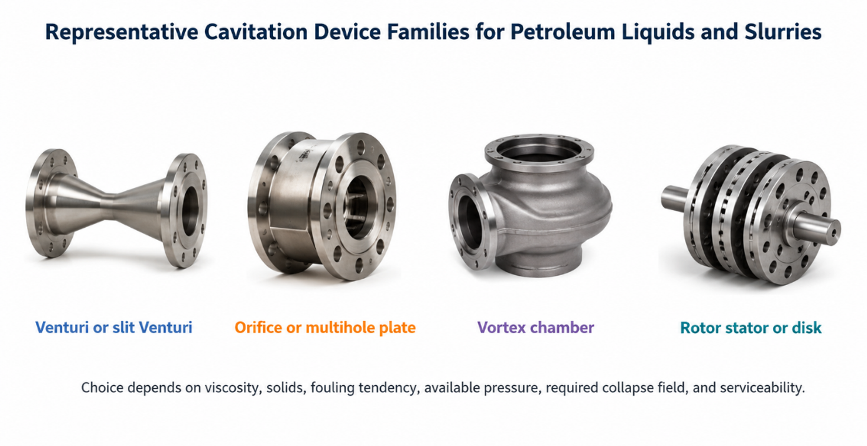
Figure 8.1. Representative cavitation device families for petroleum liquids and slurries. [70].
8.2 Viscosity, Wax, and Fractional Composition
Heavy petroleum liquids often contain a network of wax crystals, asphaltene aggregates, resins, water droplets, and fine mineral particles. Cavitation can temporarily lower apparent viscosity by disrupting this network and can improve pumpability when the treated liquid remains above the wax appearance temperature. The benefit may decay as the structure rebuilds, so viscosity should be measured at a defined shear rate, temperature, and aging time rather than immediately at the cavitator outlet [58,59].
is the relative viscosity reduction, μ₀ is the initial viscosity, and μₜ is viscosity after a stated treatment and aging protocol at the same measurement temperature and shear condition.
is the mass fraction distilled below the declared cut temperature Tcut. The cut temperature, pressure, analytical method, and untreated control must be reported.
Kuimov et al. concluded that promising experimental results have not yet resulted in broad refinery adoption because there is no unified method for comparing cavitation intensity across different oils and devices. A cavitation number based on water assumptions can be misleading in hot, viscous, multicomponent hydrocarbons containing dissolved gas and exhibiting non Newtonian behavior. Device geometry, vapor pressure model, gas release, rheology, and thermal balance must therefore be evaluated together [58].
8.3 Oil Sludge and Liquid Oil Waste Processing
Oil sludge treatment is a multiphase separation problem rather than a single cavitation reaction. The reviewed Russian process concept combines coarse separation, settling, dewatering, cavitation treatment, thermal conditioning, rectification, and conversion of residual solids to road construction products. Disk, rotor impulse, and resonant hydrodynamic generators were proposed to disperse solids, break associations, homogenize liquid wastes, and improve flow before conventional separation or distillation [59].
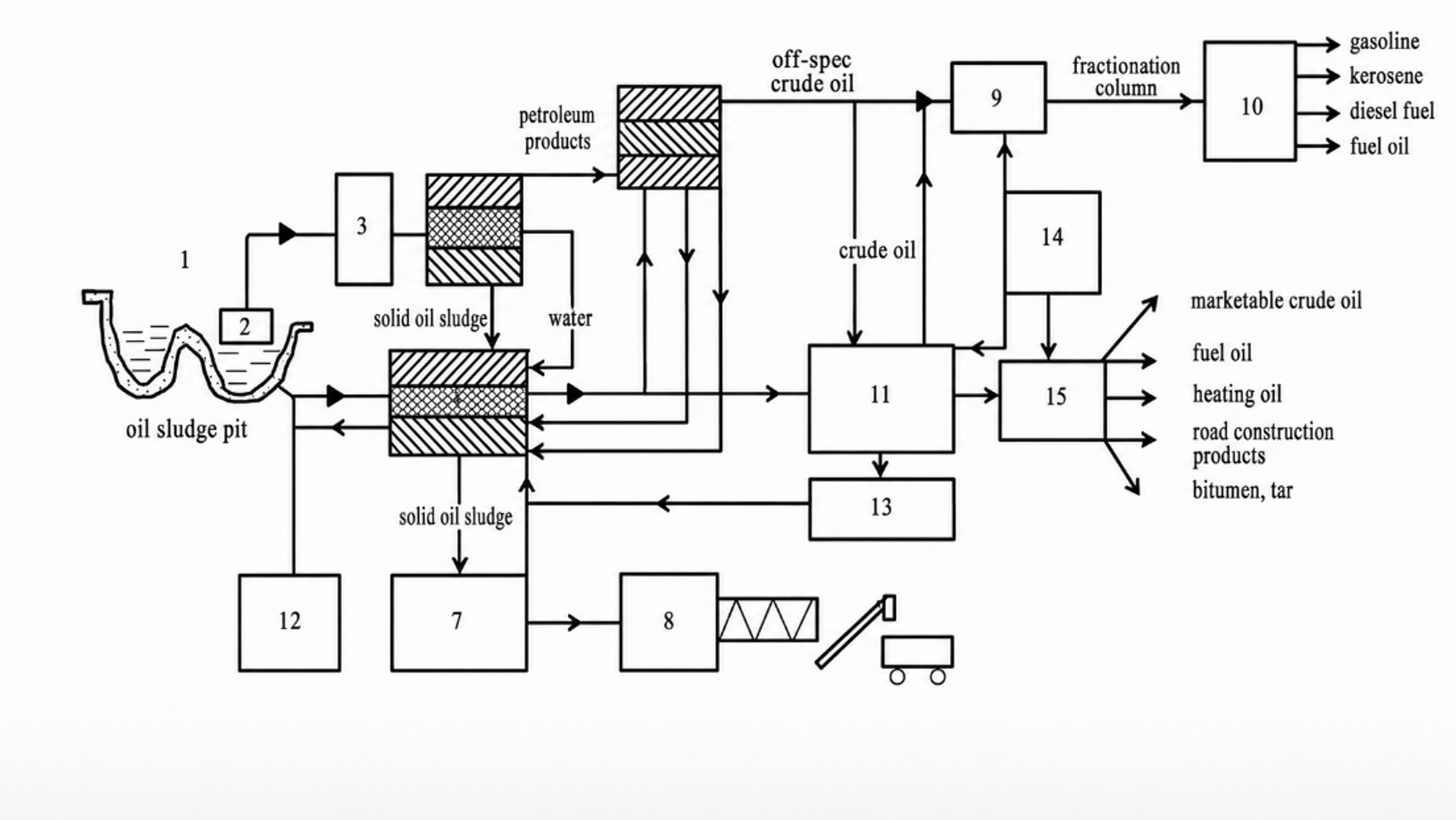
Figure 8.2. Integrated process concept for solid oil sludge and liquid oil waste treatment. [59].
The process flow emphasizes a sound engineering principle: cavitation is located where it improves a downstream unit operation. Free water and coarse solids are removed before high energy treatment; cavitation then improves homogenization or releases entrained phases; settling, centrifugation, rectification, or product finishing performs the actual separation. This arrangement reduces cavitator wear and prevents the hydraulic device from being assigned duties that are better performed by separators.
8.4 Equipment Selection, Wear, and Validation
Static Venturi and orifice devices are attractive when clean liquid is already pressurized, but fibrous solids, coke, sand, and high viscosity can cause blockage or severe pressure demand. Vortex and rotor stator devices provide larger passages and repeated exposure, although rotating seals and close clearances increase maintenance. Resonant devices can amplify pressure oscillations but must be designed for fatigue life. Materials should be selected for erosion, corrosion, temperature, and compatibility with sulfur compounds, solvents, and abrasive solids.
is specific electrical energy per treated volume, Pel is measured motor input, t is operating time, and is the actual treated volume. For recirculating systems, must not be replaced by cumulative loop flow unless the distinction is stated.
Table 8.1. Minimum validation set for petroleum cavitation trials
| Category | Required measurements | Reason |
|---|---|---|
| Feed definition | Density, viscosity curve, water, solids, wax, asphaltenes, sulfur, boiling distribution | Petroleum feed variability can exceed the treatment effect. |
| Hydraulics | Flow, pressure at defined locations, temperature, backpressure, gas fraction, power | Separates cavitation from simple heating and throttling. |
| Product response | Viscosity after controlled aging, pour point, particle size, emulsion stability, distillation curve | Distinguishes temporary dispersion from persistent compositional change. |
| Mechanical integrity | Erosion coupons, vibration, bearing and seal condition, fouling, pressure drift | High solids and vapor collapse can damage the device or change its operating window. |
| Economics and safety | Energy, maintenance, hazardous area classification, vent treatment, cleaning frequency | Determines whether a laboratory effect can be deployed in a refinery or waste facility. |
9 Critical Minerals, Spent Catalysts, and Lithium Processing
9.1 Scope and Process Integration
Lithium is produced from continental brines, geothermal or oilfield brines, hard rock minerals such as spodumene, clays, and recycled lithium ion batteries. Selective separation is governed by mineralogy, acid or alkali chemistry, magnesium to lithium ratio, impurity precipitation, solvent or sorbent selectivity, and product crystallization. Cavitation does not provide lithium selectivity by itself. Its credible role is process intensification: exposing fresh surface, dispersing reagents, accelerating leaching, improving gas liquid carbonation, conditioning particles for flotation, and controlling nucleation [13,35-37].
Direct peer reviewed evidence for hydrodynamic cavitation in primary lithium extraction remains limited. Ultrasound assisted cavitation provides the strongest adjacent evidence. Okonkwo et al. used ultrasound with molasses and methanesulfonic acid to intensify leaching of Li, Co, Ni, and Mn from spent batteries [35]. These observations support the mechanisms of surface cleaning, fragmentation, boundary layer disruption, and reagent transport, but acoustic cavitation cannot be assumed to reproduce the energy distribution or scale behavior of a continuous hydrodynamic device. Comparative development should therefore use equal specific energy and equal temperature history for HC, mechanical agitation, and ultrasound.
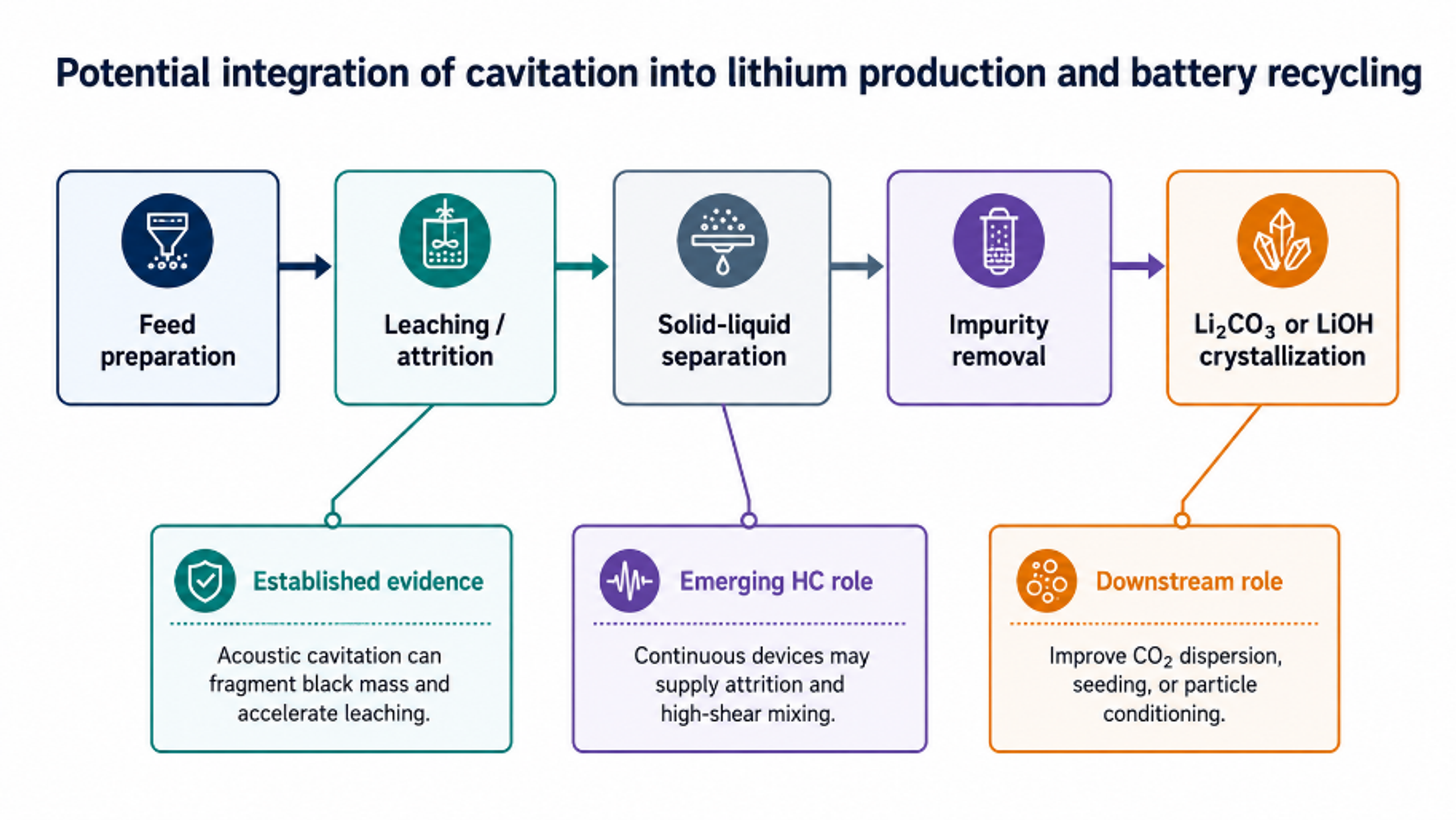
Figure 9.1. Potential integration of cavitation into lithium production and battery recycling. [70].
9.2 Leaching and Particle Activation
In hard rock and black mass leaching, reaction rate can be limited by surface films, product layers, agglomeration, and diffusion through the liquid boundary layer. A rotor stator, orifice, Venturi, or vortex cavitation device can recirculate slurry and impose repeated pressure, shear, and impact events. Expected benefits include deagglomeration, removal of passivating films, improved wetting, and increased mass transfer coefficients. Potential disadvantages include excessive fines, separator loading, erosion, and contamination from device materials.
Scale up must preserve slurry transport and avoid plugging. A bypass or recirculation loop is often more practical than placing the restriction in the full solids flow. Solids concentration, maximum particle size, hardness, gas generation, and viscosity should be included in the design. Temperature rise from hydraulic energy must be measured because apparent cavitation benefits can otherwise be attributed incorrectly to heating.
Lithium recovery must be reported on a lithium mass basis, not only as solution concentration.
X is fractional leaching conversion, kapp is an apparent rate constant that combines reaction and transport, and n is an empirical reaction order.
is lithium recovery yield per electrical energy, a useful comparison metric for alternative intensification methods.
9.3 Carbonation, Precipitation, and Impurity Control
Lithium carbonate production requires controlled supersaturation and impurity management. Cavitation can improve carbon dioxide dispersion or promote seed generation, analogous to the calcium carbonate crystallization results discussed earlier. It can also be counterproductive if uncontrolled nucleation produces ultrafine crystals that are difficult to filter or if magnesium and calcium co precipitate. Battaglia and coworkers reported up to 80% lithium recovery and 99% product purity in a NaOH/CO2 process with an ethanol wash, emphasizing the influence of magnesium, calcium, and sulfate [36]. Baum and coworkers reviewed the need to integrate extraction, concentration, and purification rather than optimizing a single unit operation [37].
Lithium carbonate precipitation depends on activity, temperature, ionic strength, and competing ions.
S is supersaturation ratio, is the ion activity product, and Ksp is the solubility product. Nucleation increases sharply above the metastable zone.
Table 9.1. Potential cavitation integration points in lithium production
| Process step | Potential cavitation function | Expected benefit | Principal uncertainty |
|---|---|---|---|
| Ore or black mass slurry preparation | Deagglomeration, wetting, attrition | Higher exposed surface and more uniform reagent contact | Erosion, fines generation, plugging and metal contamination |
| Acid/alkali leaching | Boundary layer disruption and surface cleaning | Faster kinetics or lower reagent/temperature requirement | Selectivity and energy benefit must be proved at equal temperature |
| Brine carbonation | CO2 dispersion and gas liquid mass transfer | Faster carbonate formation or pH adjustment | Co precipitation of Mg/Ca and gas disengagement |
| Seed crystallization | Nucleation and secondary attrition | Controlled induction time and potential continuous operation | Ultrafine crystals may be difficult to filter |
| Impurity or mineral flotation | Fine bubble generation and surface activation | Improved recovery of selected hydrophobic phases | Requires selective reagent chemistry; HC is not selective alone |
9.4 Uranium, Rare Earths, and Other Solid Liquid Leaching Systems
The same boundary layer disruption and particle activation mechanisms apply to uranium ores, rare earth bearing solids, spent catalysts, and other critical mineral feeds. Cavitation reduces the stagnant liquid film, exposes fresh mineral surface, fragments weak product layers, disperses agglomerates, and can accelerate redox reactions when the required oxidant or lixiviant is present. It does not replace mineral specific chemistry, grinding, solid liquid separation, solvent extraction, or ion exchange [68].
This simplified oxidation step illustrates ferric oxidation of tetravalent uranium before dissolution in an acidic leach. Actual solution chemistry includes uranyl complexes and mineral specific reactions [68].
Experiments reviewed by Ladola and coworkers reported enhanced uranium leaching under cavitation, but the evidence base is small and feed dependent. Scale up must address abrasive wear, acid compatibility, radiological containment, off gas, fine solids, and the possibility that cavitation creates a difficult to filter colloidal fraction. For radioactive or toxic materials, the reactor and sampling system must remain fully enclosed, and the benefit must be demonstrated at equal reagent dose, temperature, particle size, and electrical energy [68].
10 Cavitating Jet Cleaning and Surface Treatment
10.1 Cleaning Mechanism and Nozzle Operating Window
A submerged cavitating jet issues from a nozzle into water and forms a vapor cloud or vortex cavity. The cavity convects toward the target, fragments into clouds, and collapses as pressure recovers or the jet impinges on the surface. Collapse generates pressure pulses, microjets, and fluctuating shear that undermine deposits. Relative to a solid high pressure jet, a properly tuned cavitating jet can provide strong deposit removal at lower stagnation pressure and distribute impact over a broader footprint [1,38-42].
Cleaning performance depends on nozzle geometry, pressure, flow, cavitation number, standoff distance, traverse speed, angle, water temperature, target curvature, deposit adhesion, and coating properties. There is usually an optimum standoff: too close and the cavity has not developed; too far and collapse occurs before the target. The optimum shifts with backpressure, nozzle scale, and gas content.
is idealized jet velocity and is discharge coefficient.
is jet dynamic pressure. Cavitation collapse can create local transient pressures much higher than the mean dynamic pressure.
The dimensionless standoff ratio uses target distance S and nozzle diameter .
is specific cleaning energy per cleaned area; Aclean is verified area reaching the cleanliness criterion.
RA is the areal cleaning rate and should be reported with deposit type, thickness, substrate, and damage criterion.
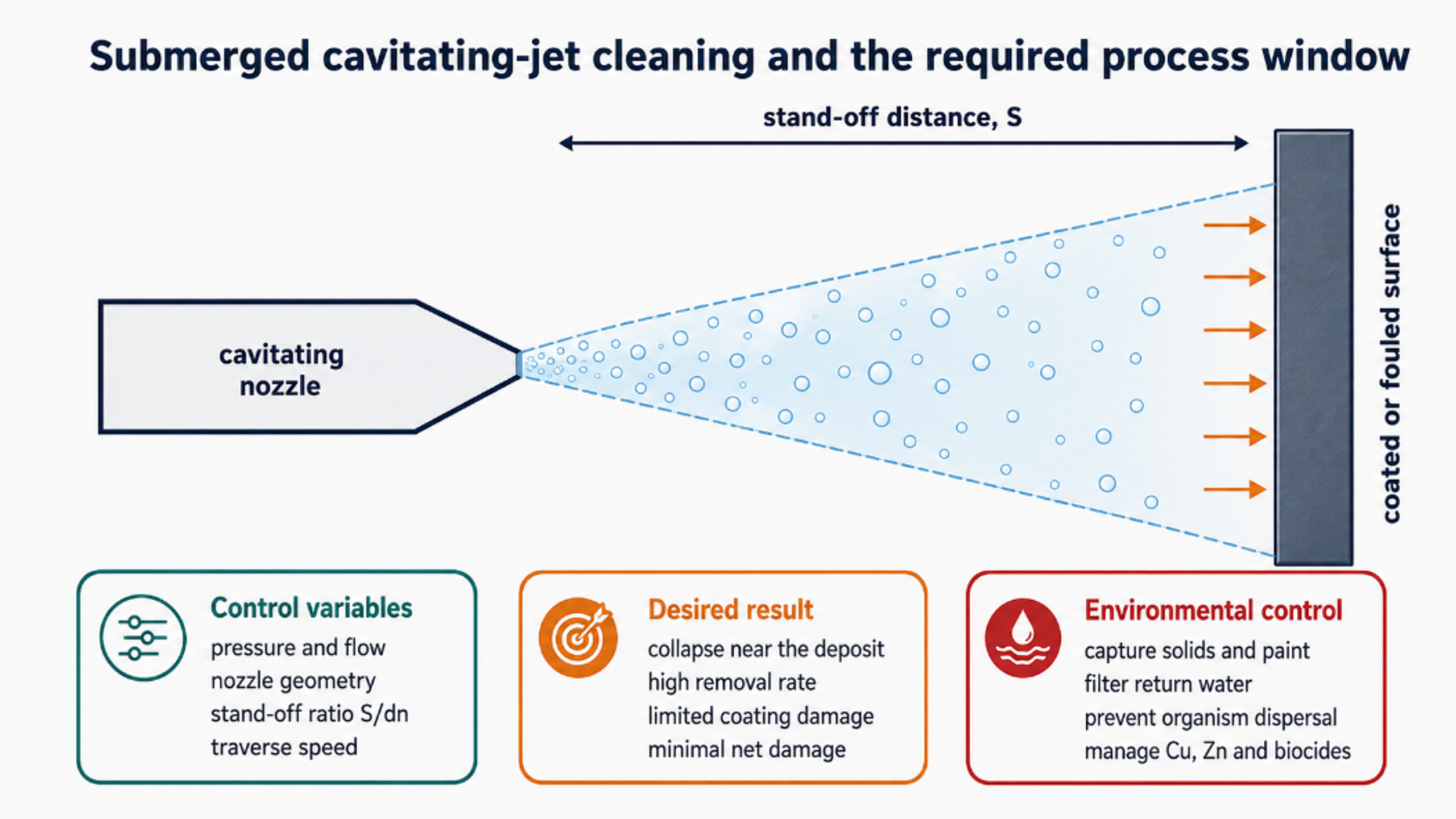
Figure 10.1. Submerged cavitating jet cleaning and the required process window. [70].
10.2 Marine Vessel Maintenance
Underwater cleaning allows hulls, propellers, rudders, bow thrusters, sea chests, and appendages to be serviced without full dry docking. The operational benefit can be substantial when fouling raises drag and fuel consumption. Cavitation cleaning is particularly attractive where the objective is to detach barnacles and soft fouling while preserving an antifouling coating.
An early CAVIJET program reported laboratory removal rates of 900-1030 ft²/h from heavily fouled submerged panels using 1/4 in. or dual 1/8 in. nozzles at 1500-2000 psi [40]. Modern studies place equal emphasis on coating damage and biosecurity. Bloecher et al. found high cleaning efficacy for both cavitation and high pressure cleaning on aquaculture nets, but a single high pressure treatment caused up to 53% coating degradation compared with 2% for cavitation [38]. Cleaning efficacy alone is therefore insufficient; coating mass loss, surface roughness, tensile strength, debris size distribution, and contaminant release should also be measured.
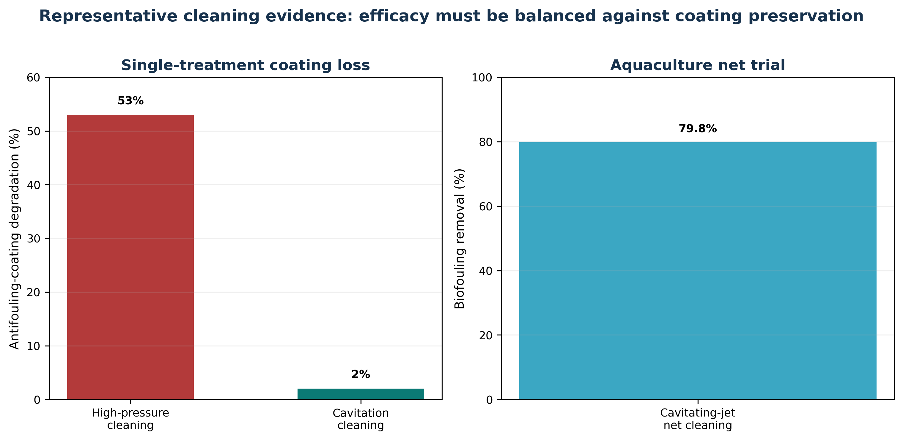
Figure 10.2. Representative cleaning evidence: efficacy must be balanced against coating preservation. [38].
10.3 Offshore Energy Infrastructure
Oil platforms, wind turbine foundations, risers, subsea pipelines, mooring chains, intake structures, and remotely operated vehicle components accumulate marine growth and mineral scale. Cavitating jets can be mounted on crawler, ROV, or diver held tools. Offshore design adds constraints absent from a laboratory panel: large ambient pressure, currents, complex curvature, poor visibility, remote power, hose losses, corrosion, and debris recovery.
The system should be qualified against representative coatings and cathodic protection components. High pressure cleaning can expose steel or damage thermal spray aluminum, elastomers, composite wraps, subsea cables, and anodes. Cavitation intensity should be sufficient to remove the deposit but not to initiate pitting or delamination. For inspection cleaning, a lower intensity pass may be preferable to full surface preparation.
10.4 Aquaculture Net Boxes
Aquaculture nets must remain permeable to maintain oxygen supply and waste transport. In situ cleaning avoids net exchange, but detached biofouling can enter the cage, expose fish to pathogens, and spread nonindigenous organisms. Copper- or zinc containing antifouling coatings create an additional contaminant pathway. Measurements from hydroblasting effluent have shown high copper and zinc concentrations, demonstrating the need for capture and management rather than assuming that underwater cleaning is pollution free [42].
A cavitation cleaner should therefore be integrated with suction, collection skirts, filtration, or controlled cleaning zones where practical. Operating procedures should address fish behavior, noise, suspended solids, dissolved oxygen, disease transmission, and cleaning frequency. Frequent low damage cleaning before heavy fouling develops may be superior to infrequent aggressive cleaning.
Table 10.1. Cavitation jet cleaning applications and qualification criteria
| Asset | Cleaning target | Qualification metric | Environmental control |
|---|---|---|---|
| Ship hull and propulsor | Barnacles, slime, calcareous fouling | Removal rate, coating loss, roughness, propeller balance | Debris capture, invasive species protocol, paint particle control |
| Offshore platform and riser | Dense marine growth, scale, inspection access | Standoff tolerance, curvature coverage, substrate damage | ROV collection, turbidity and coating debris management |
| Subsea pipeline and chain | Biofouling, mineral deposit, corrosion product scale | Coverage, residual thickness, pitting inspection | Prevent redistribution to sensitive habitat |
| Aquaculture net | Hydroids, algae, mussels, biofilm | Net permeability, coating loss, tensile strength, fish exposure | Suction or collection, Cu/Zn analysis, and pathogen control |
10.5 Nozzle Design, Tool Wear, and Surface Qualification
Cavitating nozzle design follows two broad strategies. A high discharge coefficient design preserves jet momentum and relies mainly on hydrodynamic impact. A cavitation amplifying design deliberately introduces sharp edges, deflectors, resonant chambers, or internal disturbances to increase vapor cloud formation. The preferred design depends on deposit strength, target standoff, ambient pressure, available pump power, and the allowable damage to the substrate [69].
The nozzle is a consumable erosion component. Surface finish, throat geometry, material hardness, corrosion resistance, and internal stress concentration determine service life. The reviewed oil and gas literature describes bronze as suitable for short prototype service and more resistant materials for severe duty. Modern systems may use hardened steel, tungsten carbide, ceramic, or replaceable inserts. Qualification should measure nozzle mass loss and geometry drift because throat wear changes both flow and cavitation intensity [25,69].
Cleaning acceptance must include the condition of the underlying surface. Deposit removal rate alone is insufficient when the asset carries a protective coating, fatigue sensitive weld, polymer liner, or biological containment requirement. A practical test matrix varies pressure, standoff, traverse speed, nozzle angle, and number of passes while measuring residual fouling, coating loss, roughness, erosion depth, captured debris, and water quality. The BSEE cavitating water jet program provides an early government documented example of this qualification approach for marine growth removal [64].
11 Drilling and Well Stimulation
11.1 Cavitation Jets and Self Resonating Nozzles
A conventional bit uses drilling fluid jets to cool cutters and remove cuttings. A cavitating or self resonating nozzle converts steady flow into an unsteady jet with periodic pressure fluctuations and cavitation clouds. Organ pipe, Helmholtz, or feedback geometries can generate self excited oscillation without moving mechanical parts. The design objective is to position repeated collapse and impact events at the rock face while maintaining sufficient crossflow to transport cuttings [43-48].
Hydrostatic bottomhole pressure suppresses cavitation and shortens the cavity. Higher pump pressure, appropriate nozzle geometry, gas content, and resonance tuning can compensate, but each increases complexity or erosion risk. Mud density, viscosity, solids, gas, temperature, and nozzle wear shift the resonant condition. Field performance therefore depends on maintaining the hydraulic state, not simply installing a nominally cavitating nozzle.
11.2 Rock Destruction and Cutter Assistance
When cavitation clouds collapse against the bottom of the hole, pressure pulses and microjets extend surface flaws, remove weak grains, and reduce the confinement immediately ahead of the cutter. The jet is not necessarily intended to excavate the entire hole. A smaller amount of hydraulic damage can reduce cutter force, expose fresh rock, and assist a tricone, PDC, or hybrid bit.
Li and coworkers reported that an organ pipe self resonating nozzle increased pressure fluctuation amplitude by 24%, maximum impact pressure by 37%, and rock erosion by one to two times relative to a conventional nozzle in their tests. Field applications reportedly increased average tricone rate of penetration by 31.2% and bit footage by 29.1% [43]. These results are application specific, but they demonstrate the combined role of pulsation and cavitation rather than steady jet pressure alone.
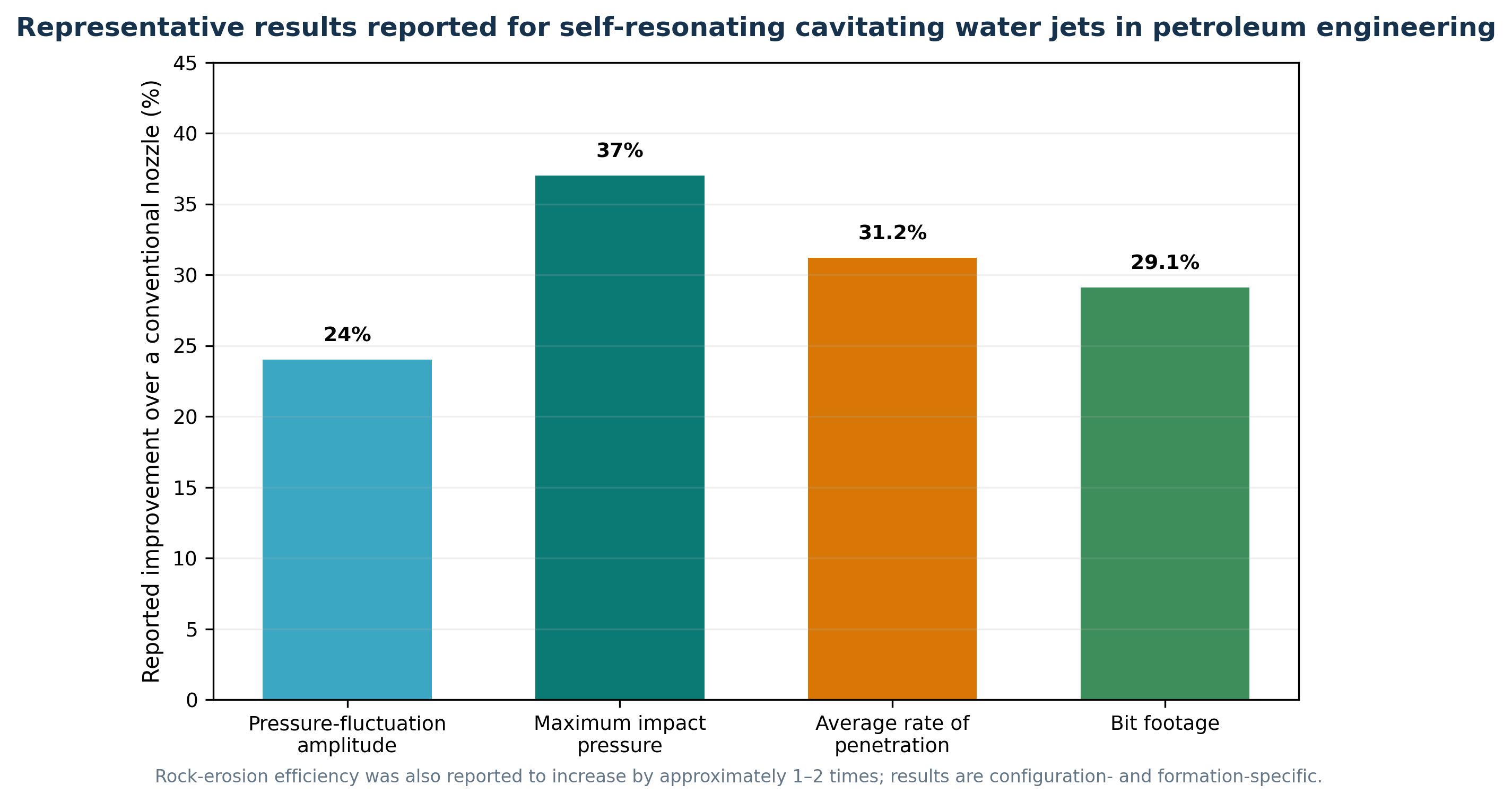
Figure 11.1. Representative results reported for self resonating cavitating water jets in petroleum engineering. [43].
11.3 Bottomhole Cleaning and Regrinding Control
Cuttings that remain under a cutter are reground instead of transported into the annulus. Regrinding consumes mechanical energy, raises temperature, and can accelerate bit wear. A pulsating jet intermittently increases wall shear and crossflow, breaks filter cake, and lifts chips from pockets between cutters. The hydraulic design should therefore be evaluated by both rock damage and bottomhole cleaning efficiency. High impact at the wrong location can erode the bit body or enlarge the hole without increasing penetration.
Annular transport remains governed by mud rheology, cuttings size and density, inclination, pipe rotation, eccentricity, and flow rate. Cavitation assisted bit cleaning does not replace adequate annular velocity or hole cleaning practices.
Pbit is the hydraulic power dissipated across the bit nozzles in SI units.
This oilfield unit equation gives hydraulic horsepower at the bit, neglecting pump/mechanical efficiency.
is average annular velocity and Aann is annular flow area. Local velocity can differ substantially in inclined or eccentric holes.
Mechanical specific energy combines weight on bit WOB, bit area Ab, rotary speed N, torque T, and rate of penetration ROP. Unit consistency is essential.
Improvement should be compared at matched formation, bit, WOB, rotary speed, mud properties, and hydraulic power.
11.4 Sonic Hydrovibrators and Downhole Stimulation
Downhole hydrovibrators convert steady mud flow into pressure pulses and axial vibration. Cavitation can participate in the feedback mechanism or occur in a resonant chamber. The vibration reduces static friction, helps weight transfer to the bit, and may improve penetration through hard or interbedded formations. The useful frequency must be distinguished from damaging drill string resonance. Accelerometers, standpipe pressure spectra, and fatigue analysis are required.
Cavitation spray guns and oscillating jet tools are also used to wash sand bridges, clean perforations, remove scale, and stimulate near wellbore flow. Here the target is controlled erosion of deposits rather than uncontrolled damage to casing, cement, or formation. Tool qualification should include causing material loss, perforation geometry, debris return, pressure containment, and compatibility with completion fluids.
Table 11.1. Cavitation assisted drilling functions, expected benefits, and constraints
| Function | Cavitation contribution | Expected benefit | Key constraints |
|---|---|---|---|
| Rock weakening | Collapse pressure, microjets, cyclic loading | Lower cutter force and higher ROP in suitable rock | Confining pressure, standoff, rock porosity and strength |
| Bottomhole cleaning | Pulsating crossflow and chip lift | Reduced regrinding and cutter balling | Mud rheology, nozzle placement, annular transport |
| Sonic hydrovibration | Self-excited pressure pulses | Improved weight transfer and lower friction | Frequency tuning, fatigue, tool wear and telemetry |
| Perforation/scale cleaning | Localized cavitating spray | Restore inflow area and remove sand or scale | Casing/cement damage, debris handling, pressure control |
11.5 Resonant Downhole Tools and Mud Jet Augmented Bits
The ORION ST concept replaces a piston hammer with hydraulically generated resonant pressure pulses in drilling fluid. The vendor technical information describes a liquid driven tool suitable for rotating or nonrotating strings, with tunable pulse patterns between approximately 500 and 15,000 Hz and the stated capability to adapt the pulse field to changing formation conditions. These performance statements are commercial claims that require independent full scale verification under representative mud weight, depth, temperature, backpressure, and bit loading [62].
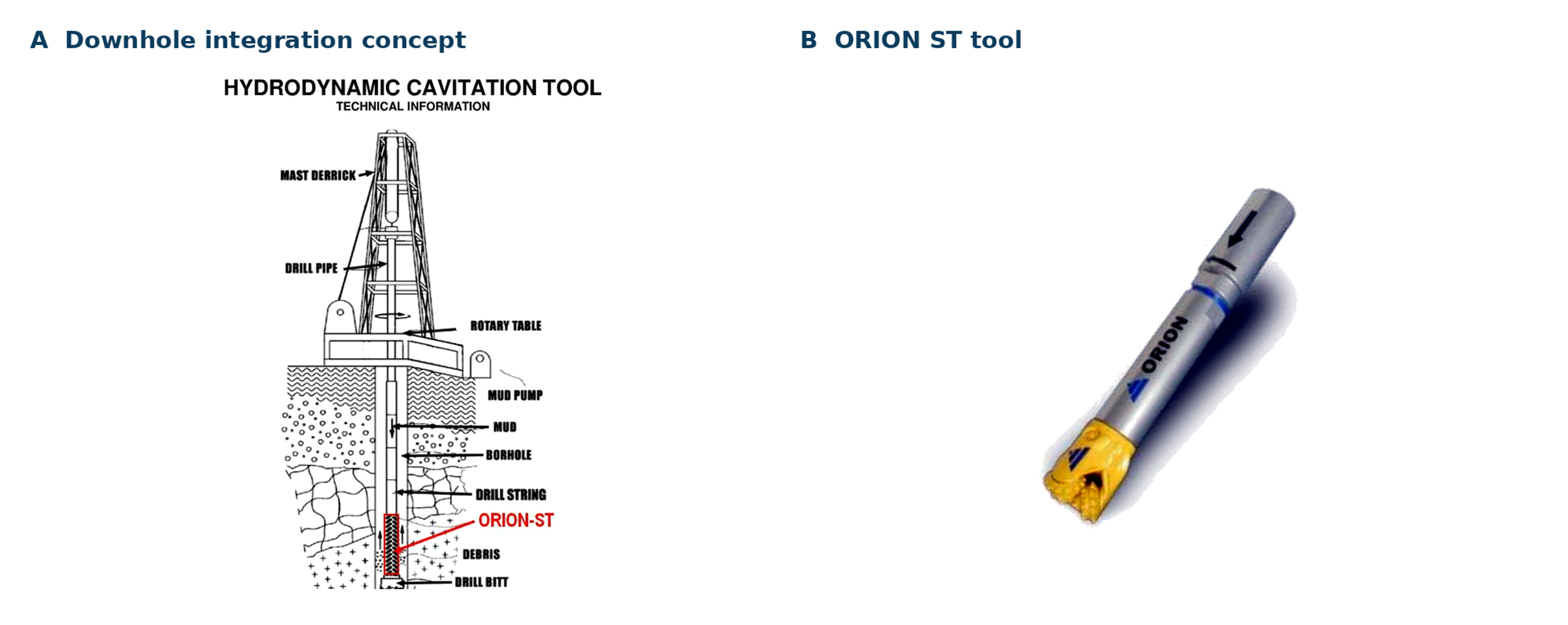
Figure 11.2. Downhole integration concept and ORION ST resonant cavitation tool. [62].
A related Sandia program developed and tested a mud jet augmented polycrystalline diamond compact bit. The design directed structured, pulsed, cavitating jets at the rock immediately ahead of the cutters. The engineering objective was to weaken the rock, improve bottomhole cleaning, and reduce the mechanical work required from the cutters. The report emphasizes that nozzle orientation, hydraulic power allocation, bit geometry, and standoff must be optimized together; adding pressure drop to an otherwise conventional bit does not guarantee higher penetration [63].
For both resonant tools and mud jet bits, the acceptance test should compare rate of penetration, mechanical specific energy, torque, vibration, bit wear, hydraulic horsepower, cuttings size, and hole quality against a conventional reference at equal formation and operating conditions. The tool must also remain stable as borehole backpressure rises and as mud rheology, gas content, and abrasive solids change.
12 Cross Application Design, Monitoring, Safety, and Scale Up
12.1 Select the Cavitation Function Before Selecting the Device
The first design decision is the required physical function. Collapse dominated treatment favors rapid pressure recovery, asymmetric collapse near a target, and high local stress. Stable microbubble generation favors controlled gas entry, sufficient low pressure residence, and pressure recovery that disperses rather than immediately destroys the gas phase. Degassing requires nucleation followed by deliberate coalescence and venting. Extraction and leaching require repeated solid liquid contact without unacceptable grinding, oxidation, or fouling. A single cavitator cannot be optimized for all of these duties simultaneously.
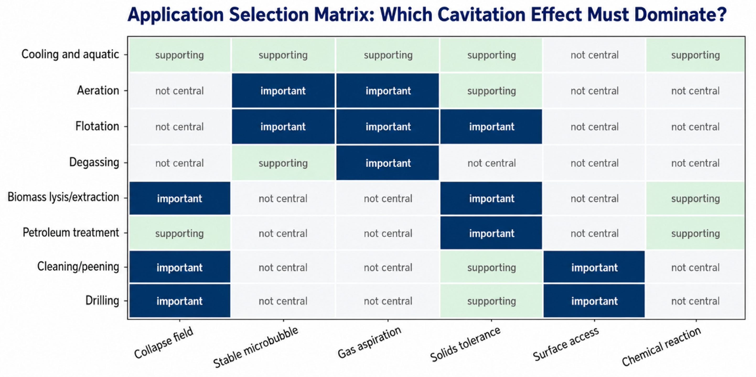
Figure 12.1. Application selection matrix showing which cavitation effect should dominate. Author synthesis from the evidence reviewed in this article. [70].
12.2 Instrumentation and Performance Indicators
Every pilot and commercial system should measure actual flow, pressure at defined locations, temperature, backpressure, gas flow where used, motor electrical power, and the response variable that justifies treatment. A pressure gauge upstream and downstream of the skid is not enough when the controlling event occurs at a throat, vortex core, nozzle exit, or rotating gap. Pressure taps, calibrated flow measurement, vibration or acoustic monitoring, dissolved gas, and representative sampling are selected according to the application.
SEC is the instantaneous specific electrical energy rate per unit treated mass, Pₑₗ is measured electrical power, ρ is liquid density, and Q is volumetric flow. Integration over time is required when power or flow varies.
Performance should be normalized to the treated load. Examples include kilograms of oxygen transferred per kilowatt hour, kilograms of recovered mineral per kilowatt hour, mass of extract per unit dry feed and energy, area cleaned per kilowatt hour, or penetration gained per unit hydraulic power. Reporting only percentage removal can conceal dilution, changing feed concentration, additional chemicals, or unreported recirculation.
12.3 Scale Up and Similarity
Geometric scale up at constant pressure drop is rarely sufficient. The relevant similarity set may include cavitation number, Reynolds number, Weber number, gas fraction, solids loading, throat perimeter to area ratio, length to diameter ratio, pressure recovery gradient, standoff ratio, pass count, and the location of the collapse zone. The appropriate subset depends on whether the target is a molecule, cell, particle, bubble, deposit, or rock surface.
denotes the application specific set of dimensionless and operational variables that must be matched or deliberately changed during scale up. No single member of the set is a universal cavitation severity index.
A scale up study should separate local similarity from system exposure. Local similarity governs cavity inception, growth, and collapse inside the device. System exposure governs how often material returns, how evenly it is distributed, how heat accumulates, and whether a separator or biological basin keeps pace. Both levels must be measured before commercial capacity is predicted.
12.4 Materials, Wear, Safety, and Validation
Cavitation deliberately creates conditions that can erode metal, damage coatings, fatigue resonant elements, atomize volatile liquids, release toxic gas, or generate fine solids. Materials selection must therefore consider cavitation erosion, abrasive wear, corrosion, temperature, cyclic stress, and cleanability. Replaceable throats, liners, nozzles, and erosion coupons can convert uncontrolled failure into planned maintenance.
Safety review must address stored hydraulic energy, blocked discharge, gas accumulation, oxygen enrichment, flammable vapor, high noise, vibration, pressure pulsation, chemical compatibility, aerosol formation, and biological or radiological containment. Relief valves and interlocks should protect against both high pressure and unintended vacuum. Vent lines require safe discharge, and rotating cavitators require guarding and condition monitoring.
Table 12.1. Recommended stage gate for cavitation process development
| Stage | Required evidence | Decision criterion |
|---|---|---|
| Mechanism test | Verified cavitation state and target response with matched noncavitating controls | Demonstrate that the response is caused by the intended mechanism rather than heat, dilution, or reagent change. |
| Hydraulic pilot | Calibrated pressure, flow, gas, temperature, power, residence, and wear data | Establish a stable operating window and a reproducible material balance. |
| Application pilot | Representative feed, full downstream separation, product quality, safety controls | Meet the process target at acceptable specific energy and without unacceptable byproducts. |
| Extended field trial | Seasonal or feed variability, maintenance, corrosion, fouling, operator response | Demonstrate sustained performance and define contingency operation. |
| Commercial acceptance | Guaranteed measurement plan, spare and wear strategy, compliance documentation | Accept only metrics that can be measured continuously or verified by an agreed test protocol. |
13 Conclusions
Hydrodynamic cavitation comprises a controllable family of hydraulic states rather than a single process. Useful outcomes can arise from violent collapse, a stable gas cavity, fine bubble dispersion, gas release, solid surface impact, or repeated high shear contact. Cooling water and aquatic applications use cavitation as one component of a monitored treatment train. Aeration and flotation depend on bubble size, gas holdup, interfacial contact, and downstream separation, while degassing succeeds only when nucleated gas is coalesced and physically vented.
The emerging applications reviewed here extend the same engineering framework. Fine mineral flotation uses microbubbles to improve collision and attachment. Microalgae and biomass processing use shear, pressure pulses, and mass transfer to open biological structures, although the negative Galdieria result demonstrates that a low cavitation number alone is not a lysis criterion. Petroleum treatment may alter dispersion and rheology, but claims of permanent chemical change require rigorous thermal and analytical controls. Critical mineral leaching uses cavitation to expose fresh surface and reduce transport resistance rather than to replace lixiviant chemistry.
Cavitating jets and resonant downhole tools deliberately position collapse near a solid surface. Their value depends on standoff, ambient pressure, nozzle wear, pulse structure, debris transport, and protection of the substrate or bit. Commercial claims should be evaluated using matched reference tests and complete hydraulic power accounting. A visually prominent vapor cloud may still be ineffective if collapse occurs at the wrong location or if downstream equipment cannot use the generated bubbles or solids.
Across all applications, a defensible development sequence is to define the required function, measure local and system hydraulics, close material and energy balances, validate product quality and safety, and complete an extended field trial. Pressure drop and cavitation number are useful descriptors but are not universal severity measures. Long term value is established by the application specific outcome per unit electrical energy under realistic feed variability and with a maintainable wear, control, and monitoring strategy.
Nomenclature
| Symbol or abbreviation | Definition | Typical SI unit |
|---|---|---|
| a | Gas liquid interfacial area per liquid volume | m²/m³ |
| Bit or borehole cross sectional area | m² | |
| Aclean | Area meeting the specified cleaning criterion | m² |
| Aann | Annular flow area | m² |
| B | Cooling tower blowdown flow | m³/s |
| BOD5 | Five day biochemical oxygen demand | mg/L |
| C, C* | Bulk and equilibrium dissolved concentration | kg/m³ or mg/L |
| Cd | Discharge coefficient | dimensionless |
| CoC | Cycles of concentration | dimensionless |
| COD | Chemical oxygen demand | mg/L |
| D, dn | Characteristic diameter and nozzle diameter | m |
| , | Bubble and particle diameter | m |
| d32 | Sauter mean bubble diameter | m |
| Dr | Drift and other cooling water losses, where used in water balance | m³/s |
| E | Evaporation flow or energy, as defined locally | m³/s or J |
| Specific cleaning energy per area | J/m² | |
| Specific electrical energy per treated volume | J/m³ or kWh/m³ | |
| FOG | Fats, oils, and grease | mg/L |
| g | Gravitational acceleration | m/s² |
| HHP | Hydraulic horsepower at the bit | hp |
| Hi | Henry law constant in the stated convention | varies with convention |
| IAP | Ion activity product | dimensionless activity product |
| k | Apparent first order flotation rate constant | s⁻¹ |
| Apparent leaching rate constant | s⁻¹ | |
| Volumetric gas liquid mass transfer coefficient | s⁻¹ or h⁻¹ | |
| Ksp | Solubility product | activity basis |
| M | Cooling tower makeup flow | m³/s |
| MLSS | Mixed liquor suspended solids | mg/L |
| MSE | Mechanical specific energy | J/m³ or equivalent drilling unit |
| N | Rotary speed | s⁻¹ or rev/min |
| Npass | Nominal number of system turnovers through the device | dimensionless |
| OTR, SOTR | Oxygen transfer rate and standardized oxygen transfer rate | kg O2/h |
| OUR | Oxygen uptake rate | kg O2/(m³·h) |
| p, pref, pv | Pressure, reference pressure, and vapor pressure | Pa |
| Pa, Pc, Pd | Attachment, collision, and detachment probabilities | dimensionless |
| Pel, Ph, Pbit | Electrical, hydraulic, and bit hydraulic power | W |
| Q | Volumetric liquid flow rate | m³/s |
| Jet dynamic pressure | Pa | |
| R, Rmax | Bubble radius and maximum bubble radius | m |
| Areal cleaning rate | m²/s | |
| ROP | Rate of penetration | m/s or m/h |
| S | Standoff distance or supersaturation ratio, as defined locally | m or dimensionless |
| S* | Dimensionless standoff ratio | dimensionless |
| Bubble surface area flux | m²/(m²·s) | |
| t, tc | Time and Rayleigh collapse time | s |
| T | Torque | N·m |
| TSS | Total suspended solids | mg/L |
| v, , | Local velocity, jet velocity, and terminal rise velocity | m/s |
| V, Vsys, | Liquid, system, and treated volumes | m³ |
| WOB | Weight on bit | N |
| X | Fractional leaching conversion | dimensionless |
| Lithium recovery per electrical energy | kg/kWh | |
| z | Elevation | m |
| C0, Ct | Initial and treated concentration of the measured constituent | kg/m³, mg/L, or process specific |
| DL | Cell disruption or lysis fraction | dimensionless or % |
| Es | Specific electrical energy per unit dry solids | J/kg or kWh/kg |
| NT | Number of treated hydraulic turnovers during an evaluation period | dimensionless |
| Ndamaged, Ntotal | Count of damaged cells and total cells evaluated | count |
| SEC | Specific electrical energy consumption based on treated mass or volume | J/kg or kWh/m³ |
| mdry, mproduct | Dry feed mass and recovered product mass | kg |
| Yext | Dry extract yield based on dry feed | dimensionless or % |
| Ylight | Yield of distillate or light fraction below a stated cut temperature | dimensionless or % |
| , | Initial and treated dynamic viscosity | Pa·s |
Greek Letters
| Symbol | Definition | Typical SI unit |
|---|---|---|
| α | Process water correction factor for oxygen transfer | dimensionless |
| β | Open area ratio or oxygen solubility correction factor, as defined locally | dimensionless |
| γ | Liquid surface tension | N/m |
| Δp | Pressure drop | Pa |
| εg | Gas holdup | dimensionless |
| ηp, ηm | Pump and motor efficiencies | dimensionless |
| ηLi, ηstrip | Lithium recovery and gas stripping efficiency | dimensionless or % |
| μ | Dynamic viscosity | Pa·s |
| ρ, ρl, ρg | Density, liquid density, and gas density | kg/m³ |
| σ | Cavitation number | dimensionless |
| τ | Contact or residence time | s |
| Πscale | Set of scale up similarity variables | dimensionless set |
| ηHS | Humic substance removal efficiency | dimensionless or % |
| ημ | Relative viscosity reduction | dimensionless or % |
Bibliography
[1] Brennen, C. E. Cavitation and Bubble Dynamics. Oxford University Press: New York, 1995.
[2] Dular, M.; Griessler Bulc, T.; Gutierrez Aguirre, I.; Heath, E.; Kosjek, T.; Klemenčič, A. K.; Oder, M.; Petkovšek, M.; Rački, N.; Ravnikar, M.; Šarc, A.; Širok, B.; Zupanc, M.; Žitnik, M.; Kompare, B. Use of hydrodynamic cavitation in (waste)water treatment. Ultrasonics Sonochemistry 2016, 29, 577-588. https://doi.org/10.1016/j.ultsonch.2015.10.010.
[3] Simpson, A.; Ranade, V. V. Flow characteristics of vortex based cavitation devices: computational investigation on influence of operating parameters and scale. AIChE Journal 2019, 65, e16675. https://doi.org/10.1002/aic.16675.
[4] Simpson, A.; Ranade, V. V. Comparison of cavitation devices based on linear and swirling flows: hydrodynamic characteristics. Industrial & Engineering Chemistry Research 2019, 58, 14488-14509. https://doi.org/10.1021/acs.iecr.9b02757.
[5] Suslick, K. S.; Mdleleni, M. M.; Ries, J. T. Chemistry induced by hydrodynamic cavitation. Journal of the American Chemical Society 1997, 119, 9303-9304. https://doi.org/10.1021/ja972171i.
[6] Gogate, P. R.; Pandit, A. B. Hydrodynamic cavitation reactors: a state of the art review. Reviews in Chemical Engineering 2001, 17, 1-85.
[7] Gaines, W. A.; Kim, B. R.; Drews, A. R.; Bailey, C.; Loch, T.; Frenette, S. Controlling cooling tower water quality by hydrodynamic cavitation. ASHRAE Transactions 2007, 113(2), Paper LB-07-028.
[8] Kitzman, K. A.; Maziarz, E. F.; Padgett, B.; Blumenschein, C. D.; Smith, A. Chemical vs. nonchemical cooling water treatments: a side by side comparison. International Water Conference, Paper IWC-03-22, 2003.
[9] Burge, D. Controlled hydrodynamic cavitation for cooling tower water treatment. Cooling Technology Institute Annual Conference, Paper TP15-22, New Orleans, 2015.
[10] Vella, P. Water conservation in cooling towers using controlled hydrodynamic cavitation. WaterSmart Innovations Conference, Las Vegas, 2008.
[11] Harris, A. Kinetic energy + hydrodynamic cavitation + chemical equilibrium = cooling tower water treatment. Water Conditioning & Purification, April 2008.
[12] Grogan, L.; Bizzozero, R.; Cain, J. The Strategic Envirotechnology Partnership Green Book Technology Summary Report Utilizing VRTX Technology. Massachusetts Office of Technical Assistance: Boston, 2001.
[13] Kim, S.-J.; Park, J.-Y.; Lee, Y.-W.; Hwang, K.-W.; Lee, W.-K. Seed crystallization with cavitation for enhanced removal of calcium in water. Journal of Industrial and Engineering Chemistry 2007, 13(1), 79-83.
[14] Institute for Sustainable Process Technology. Energy efficient degassing using Vortex technology. ISPT NL GUTS project summary, Netherlands, n.d.
[15] Schmid, A. A new aeration technology using supercavitation. Recent Patents on Chemical Engineering 2009, 2, 176-180.
[16] Raut, J. S.; Stoyanov, S. D.; Duggal, C.; Pelan, E. G.; Arnaudov, L. N.; Naik, V. M. Hydrodynamic cavitation: a bottom up approach to liquid aeration. Soft Matter 2012, 8, 4562-4566. https://doi.org/10.1039/C2SM07330G.
[17] Nayak, J. K.; Ganjare, A.; Ranade, V. V. A note on enhancing aeration via a vortex based cavitation device. ACS Omega 2025, 10, 4561-4568. https://doi.org/10.1021/acsomega.4c08452.
[18] Li, W.-X.; Tang, C.-D.; Wu, Z.-L.; Wang, W.-M.; Zhang, Y.-F.; Zhao, Y.; Cravotto, G. Eutrophic water purification efficiency using a combination of hydrodynamic cavitation and ozonation on a pilot scale. Environmental Science and Pollution Research 2015, 22, 6298-6307. https://doi.org/10.1007/s11356-014-3889-1.
[19] Zhu, L.; Li, P.; Wang, C.; Hu, J.; Zhang, L.; Li, J. In situ algal control by two stage nanobubble technology in Taihu Lake: efficacy and ecological impact. Environmental Research 2024, 263, 120077. https://doi.org/10.1016/j.envres.2024.120077.
[20] Bis, M.; Montusiewicz, A.; Ozonek, J.; Pasieczna Patkowska, S. Application of hydrodynamic cavitation to improve the biodegradability of mature landfill leachate. Ultrasonics Sonochemistry 2015, 26, 378-387. https://doi.org/10.1016/j.ultsonch.2015.03.003.
[21] Feng, X. et al. A novel process for landfill leachate pretreatment using hydrodynamic cavitation combined with potassium ferrate oxidation. Journal of Chemical Technology & Biotechnology 2022, 97, 2537-2546. https://doi.org/10.1002/jctb.7126.
[22] Qiao, Y.; Jin, R.; Gao, J.; Wang, K.; Jiang, Y.; Xiong, J.; Jia, M.; He, Z.; Liu, J. Process of landfill leachate pretreatment using coagulation and hydrodynamic cavitation oxidation. RSC Advances 2023, 13, 32175-32184. https://doi.org/10.1039/D3RA04259F.
[23] Xu, M.; Zhou, Z.; Xu, Z. Pre aeration of feed. In Encyclopedia of Separation Science; Academic Press, 2000, pp. 1556-1562.
[24] Sayed Ahmed, A. S. Cavitation Nanobubble Enhanced Flotation Process for More Efficient Coal Recovery. Ph.D. Dissertation, University of Kentucky, Lexington, 2013.
[25] Canadian Process Technologies Inc. Cavitation Sparging System. Technical brochure, Delta, British Columbia, n.d.
[26] Canadian Process Technologies Inc. Cavitation Sparging System: Enhanced Column Flotation. Technical brochure, Delta, British Columbia, n.d.
[27] Loraine, G.; Chahine, G. L. Application of cavitation based micro bubbles to recover neutrally buoyant oil droplets. Conference paper and U.S. Coast Guard research project report, 2018.
[28] Al Mutairi, N. Z.; Al Sharifi, F. A.; Al Shammari, S. B. Evaluation study of a slaughterhouse wastewater treatment plant including contact assisted activated sludge and DAF. Desalination 2008, 225, 167-175. https://doi.org/10.1016/j.desal.2007.04.094.
[29] Etchepare, R.; Oliveira, H.; Azevedo, A.; Rubio, J. Separation of emulsified crude oil in saline water by dissolved air flotation with micro and nanobubbles. Separation and Purification Technology 2017, 186, 326-332. https://doi.org/10.1016/j.seppur.2017.06.007.
[30] Oliveira, H. A.; Azevedo, A. C.; Etchepare, R.; Rubio, J. Separation of emulsified crude oil in saline water by flotation with micro- and nanobubbles generated by a multiphase pump. Water Science & Technology 2017, 76(10), 2710-2718. https://doi.org/10.2166/wst.2017.441.
[31] Furukawa, Y. On the application of polyelectrolytes to white water treating by dissolved air flotation. Japan TAPPI Journal 1973, 27(8), 384-393. https://doi.org/10.2524/jtappij.27.8_384.
[32] Miranda, R.; Negro, C.; Blanco, A. Internal treatment of process waters in paper production by dissolved air flotation with newly developed chemicals. 2. Field trials. Industrial & Engineering Chemistry Research 2009, 48(7), 3672-3677. https://doi.org/10.1021/ie801826m.
[33] Dafnopatidou, E. K.; Lazaridis, N. K. Dyes removal from simulated and industrial textile effluents by dissolved air and dispersed air flotation techniques. Industrial & Engineering Chemistry Research 2008, 47(15), 5594-5601. https://doi.org/10.1021/ie071235n.
[34] Nalbandyan, M.; et al. Hydrodynamic cavitation assisted degassing and activation of gas nuclei in Venturi devices. Acta Periodica Technologica 2023, 54, 237-244. https://doi.org/10.2298/APT2354237N.
[35] Okonkwo, E. G.; et al. A cavitation enabled green leaching of metals from spent lithium ion batteries. Chemical Engineering and Processing, Process Intensification 2024, 202, 109850. https://doi.org/10.1016/j.cep.2024.109850.
[36] Battaglia, A.; et al. Selective recovery of lithium carbonate from lithium containing solutions by NaOH/CO2 treatment and ethanol washing. Industrial & Engineering Chemistry Research 2022, 61(36), 13589-13602. https://doi.org/10.1021/acs.iecr.2c01397.
[37] Baum, Z. J.; Bird, R. E.; Yu, X.; Ma, J. Lithium ion battery recycling, overview of techniques and trends. ACS Energy Letters 2022, 7(2), 712-719. https://doi.org/10.1021/acsenergylett.1c02602.
[38] Bloecher, N.; Frank, K.; Bondø, M.; Ribicic, D.; Endresen, P. C.; Su, B.; Floerl, O. Testing of novel net cleaning technologies for finfish aquaculture. Biofouling 2019, 35(7), 805-817. https://doi.org/10.1080/08927014.2019.1663413.
[39] Yuan, C.; et al. Experimental investigation and optimization of cavitating jet cleaning for marine fouling. Ocean Engineering 2023, 285, 115241. https://doi.org/10.1016/j.oceaneng.2023.115241.
[40] Conn, A. F.; Rudy, S. L. Parameters for a Ship Hull Cleaning System Using the Cavitating Water Jet Method. Hydronautics Report TR-7510-1; Maritime Administration Report MA-6562, 1975.
[41] Song, C.; Cui, W. Review of underwater ship hull cleaning technologies. Journal of Marine Science and Application 2020, 19, 415-429. https://doi.org/10.1007/s11804-020-00157-z.
[42] Soon, Z. Y.; Jung, J. H.; Yildiz, B.; et al. Environmental risks of in water hull cleaning: contaminant release and management. Journal of Hazardous Materials 2021, 403, 123708. https://doi.org/10.1016/j.jhazmat.2020.123708.
[43] Li, G.; Shen, Z.; Zhou, C.; et al. Investigation and application of self resonating cavitating water jet in petroleum engineering. Petroleum Science and Technology 2005, 23(1-2), 1-15. https://doi.org/10.1081/LFT-20009686218.
[44] Johnson, V. E.; Chahine, G. L.; Lindenmuth, W. T.; et al. Cavitating and structured jets for mechanical bits to increase drilling rate, Part I. Journal of Energy Resources Technology 1984, 106(2), 282-288. https://doi.org/10.1115/1.3231053.
[45] Johnson, V. E.; Chahine, G. L.; Lindenmuth, W. T.; et al. Cavitating and structured jets for mechanical bits to increase drilling rate, Part II. Journal of Energy Resources Technology 1984, 106(2), 289-294. https://doi.org/10.1115/1.3231054.
[46] Peng, K.; et al. Bubble dynamics characteristics and influencing factors on the cavitation collapse intensity for self resonating cavitating jets. Petroleum Exploration and Development 2018, 45(2), 343-350. https://doi.org/10.1016/S1876-3804(18)30038-7.
[47] Chinese Patent CN101105115A. Hydraulic pulse cavitation jet drilling device and method, published 2008.
[48] U.S. Patent US4185706. Rock bit with cavitating jet nozzles, issued 1980.
[49] U.S. Patent US3807632. Cavitating liquid jet drilling apparatus, issued 1974.
[50] U.S. Patent US7338551B2. Apparatus and method for generating microbubbles using sequential cavitating restrictions, issued 2008.
[51] International Patent WO2012065250A1. Integrated dissolved air flotation system for fats, oils and grease removal, published 2012.
[52] AquaRev Water. Hydrodynamic Cavitation for Commercial Aquatic Water Systems: Engineering Assessment, Scientific Basis, and Implementation Rationale for Hotel and Resort Facilities. Technical Engineering White Paper, Revision 1.0, April 2026.
[53] Naghashzargar, S. Microalgae Lysis through Hydrodynamic Cavitation. Master’s Thesis, Politecnico di Torino, Turin, 2025.
[54] Wu, Z.; Ferreira, D. F.; Crudo, D.; Bosco, V.; Stevanato, L.; Costale, A.; Cravotto, G. Plant and Biomass Extraction and Valorisation under Hydrodynamic Cavitation. Processes 2019, 7, 965. https://doi.org/10.3390/pr7120965.
[55] Meneguzzo, F.; Zabini, F.; Albanese, L. Green Extraction at Scale: Hydrodynamic Cavitation for Bioactive Recovery and Protein Functionalization, A Narrative Review. Molecules 2026, 31, 192. https://doi.org/10.3390/molecules31010192.
[56] Li, M. Fundamental Understanding on the Inception of Hydrodynamic Cavitation and Its Generated Microbubbles in Fine Particle Flotation. Ph.D. Thesis, University of Alberta, Edmonton, 2022.
[57] Pagan, F. S.; Mateus, M. V.; Soeira, T. V. R.; da Luz, M. S.; Ferreira, D. C.; Moruzzi, R.; Simões, A. L. A.; Gonçalves, J. C. S. I. Integrating Coagulation and Flotation via Hydrodynamic Cavitation: The Key Role of Venturi Divergent Angle for Humic Substance Removal. Clean Technologies 2026, 8, 27. https://doi.org/10.3390/cleantechnol8020027.
[58] Kuimov, D.; Minkin, M.; Yurov, A.; Lukyanov, A. Current State of Research on the Mechanism of Cavitation Effects in the Treatment of Liquid Petroleum Products, Review and Proposals for Further Research. Fluids 2023, 8, 172. https://doi.org/10.3390/fluids8060172.
[59] Vikarchuk, A. A.; Rastegaeva, I. I.; Chernokhaeva, E. Yu. Technology and Equipment for Treatment of Oil and Processing of Solid Oil Sludge and Liquid Oil Waste. Vector of Science of Togliatti State University 2012, 3(21), 70-75. In Russian.
[60] Fedotkin, I. M.; Kozyuk, O. V.; Ballalov, A. B. Apparatus for Degassing a Liquid. USSR Author’s Certificate SU 1258460 A1, published 23 September 1986.
[61] Kozyuk, O. Device and Method for Degassing Liquids. U.S. Patent 10,159,915 B2, issued 25 December 2018.
[62] NPO Special Technologies Ltd. Hydrodynamic Cavitation Tool: ORION ST Technical Information. Technical brochure, undated.
[63] Raymond, D. W.; Grossman, J. W.; Chahine, G. L.; Kalumuck, K.; Matthews, O.; Black, A.; Bertagnolli, K.; Vail, M. Development and Testing of a Mud jet Augmented PDC Bit. Sandia National Laboratories Report SAND2006-0091, 2006.
[64] Thiruvengadam, A. P. A Cavitating Water Jet Cleaning System for Removing Marine Growth. U.S. Department of the Interior, Technical Assessment Program Report 004AA, December 1979.
[65] California Energy Commission. Cooling Tower Water Treatment Using Industrial Vortex Generator Technology for Water and Energy Savings. Publication CEC-500-2021-035, 2021.
[66] Centers for Disease Control and Prevention. Model Aquatic Health Code, 5th Edition. Atlanta, Georgia, 2024.
[67] Eriez Flotation Division. Cavitation Tube Sparging Systems. Technical brochure FGB-103C, Delta, British Columbia, undated.
[68] Ladola, Y. S.; Chowdhury, S.; Roy, S. B.; Pandit, A. B. Application of Cavitation in Uranium Leaching. Desalination and Water Treatment 2014, 52, 407-414. https://doi.org/10.1080/19443994.2013.808792.
[69] Bukharin, N. S.; Omelyanyuk, M. V. Cavitating Jets in the Oil and Gas Industry. Review article, University of Calgary and Kuban State Technological University, 2014.
[70] Kozyuk O. Hydrodynamic Cavitation. [Unpublished technical manuscript and supporting data] 2026.