
Technical publication
Back to publications
Industrial applications
Emerging Frontiers in Hydrodynamic Cavitation
okozyuk.com
Published
Read complete publication for whole-document Find and printing. Browser Find and native printing on this reader include only loaded content.
6 Degassing and Gas Stripping
6.1 Two Step Mechanism: Nucleation and Disengagement
Degassing requires two distinct operations. First, the liquid must become supersaturated with respect to the local pressure so that dissolved gas forms bubbles or expands existing nuclei. Second, the bubbles must coalesce, rise, or be separated before they redissolve during pressure recovery. A cavitation device can perform the first operation very effectively but may fail as a complete degasser if the outlet immediately repressurizes the bubble laden liquid without a venting vessel [14,17,34].
This form of Henry's law uses a concentration based Henry constant Hi. Other conventions use the reciprocal constant; the convention and temperature must be stated.
For stripping, bulk concentration exceeds the equilibrium concentration associated with the gas phase partial pressure.
For an ideal first order contactor, ηstrip is fractional removal and τ is gas liquid contact time. Actual systems may be limited by bubble disengagement and back mixing.
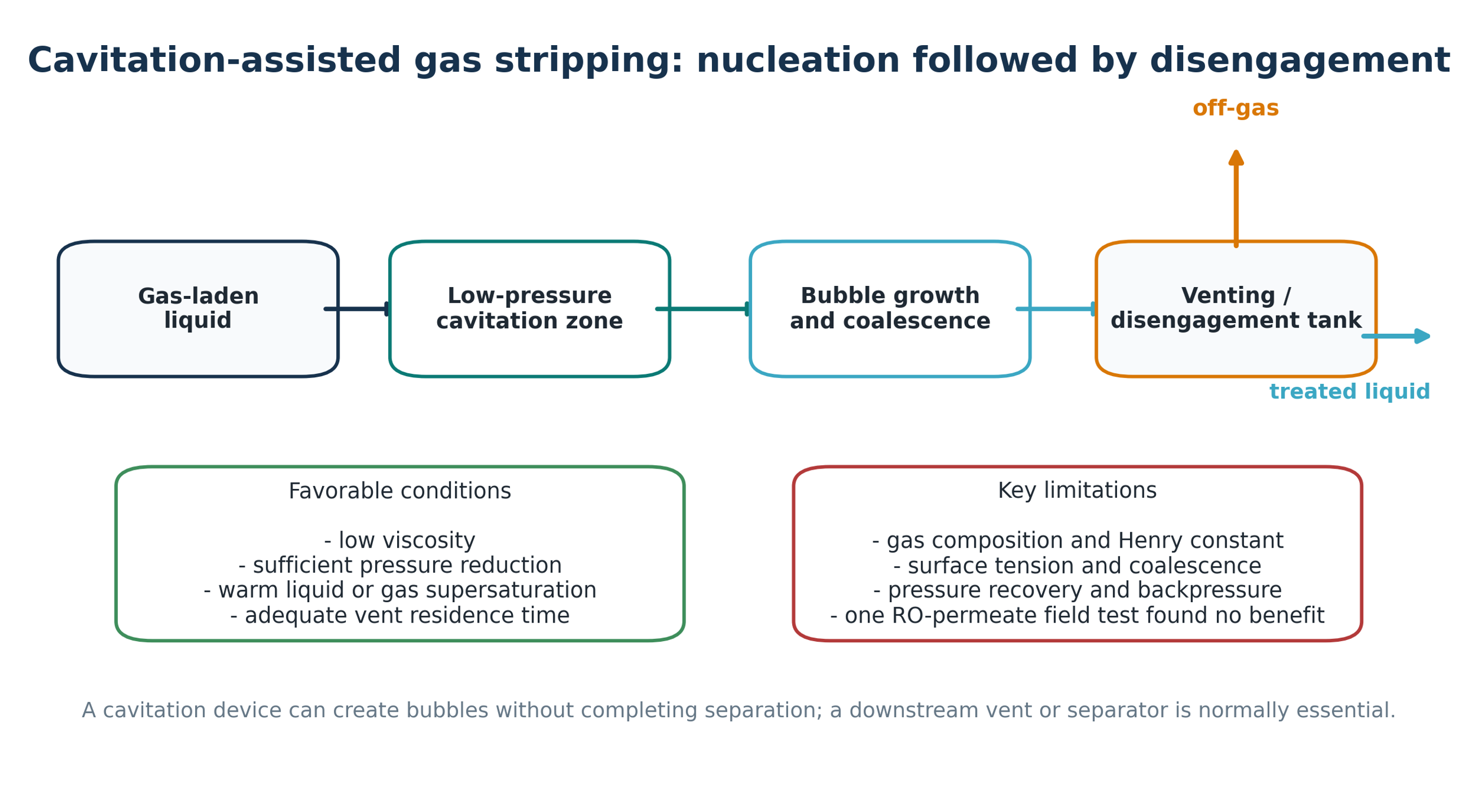
Figure 6.1. Cavitation assisted gas stripping: nucleation followed by disengagement. [70].
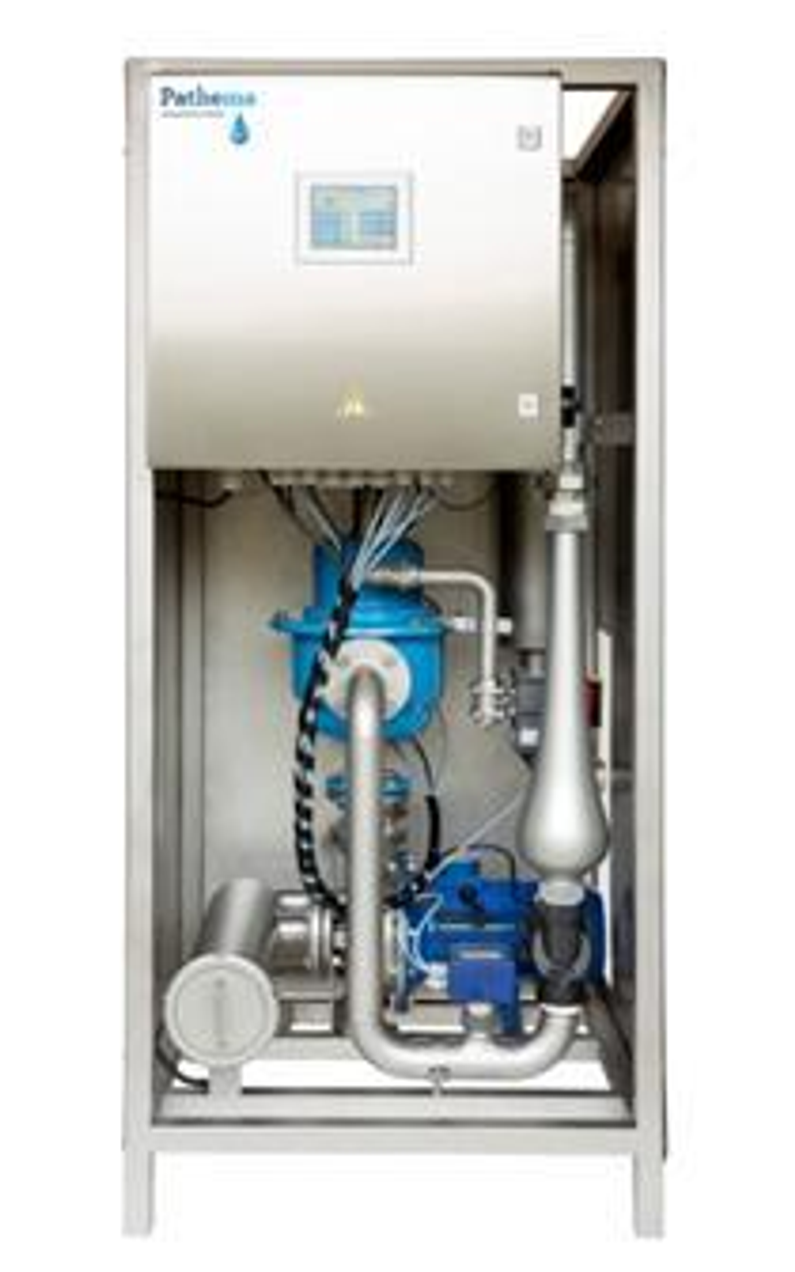
Figure 6.2. Packaged vortex treatment skid used in industrial degassing and cooling water trials. [14].
6.2 Demonstrated Uses and Limitations
The ISPT project compared three end uses. Low viscosity dairy liquids deaerated faster after vortex treatment than by spontaneous holding tank deaeration, although a small venting tank was still required. In an evaporative condenser, the treatment successfully supported chemical free scale and corrosion control. In contrast, processing reverse osmosis permeate did not reduce dissolved gases and was judged to add no value in that application [14]. These contrasting results are instructive: a low pressure zone is not sufficient if the dissolved gas loading, gas speciation, pressure recovery, temperature, or downstream separator does not create a net removal path.
Potential stripping targets include carbon dioxide, oxygen, hydrogen sulfide, methane, ammonia under favorable pH, and volatile organic compounds. Each requires a gas specific mass balance and off gas treatment. Removing oxygen may reduce oxidation and corrosion in some closed processes, but aeration may be required elsewhere. Carbon dioxide removal raises pH and can intentionally precipitate carbonate hardness but may also cause uncontrolled scaling downstream. Hydrogen sulfide and VOC stripping require enclosure, ventilation, explosion assessment, and air pollution control. The choice between cavitation, vacuum degassing, membrane contactors, steam stripping, inert gas stripping, or thermal deaeration should be based on the required residual concentration and the value of integrating the hydraulic device with another process duty.
Table 6.1. Cavitation assisted degassing applications
| Liquid and target gas | Potential benefit | Required downstream equipment | Evidence or risk |
|---|---|---|---|
| Low viscosity food liquids; entrained air | Reduced holding time and air related process defects | Small vent or disengagement tank | Positive industrial experiment [14] |
| Cooling water; CO2 | pH shift and bulk carbonate precipitation | Side stream solids separator and basin venting | Field use, but chemistry must be controlled [7–14] |
| RO permeate; dissolved air/CO2 | Potential reduction in chemical demand | Vent, vacuum or sweep gas if pressure recovery is insufficient | Uploaded field experiment found no removal [14] |
| Closed process liquid; O2 | Reduced oxidation or corrosion | Gas tight separator and oxygen control | Application specific; avoid microbial anaerobiosis |
| Leachate or wastewater; H2S/VOCs | Odor and toxicity reduction | Enclosed off gas collection and treatment | Uncontrolled stripping transfers pollution to air |
6.3 Engineered Cavitation Degassers and Bubble Coalescers
Patented cavitation degassers illustrate why nucleation and separation should be designed as distinct hydraulic functions. The Soviet apparatus SU 1258460 A1 places a cavitation element in a working chamber, draws gas through a vacuum outlet, and uses a diffuser and conical recovery chamber to enlarge the gas liquid interface and discharge liberated gas. The stated design objective was higher throughput with lower specific energy [60].
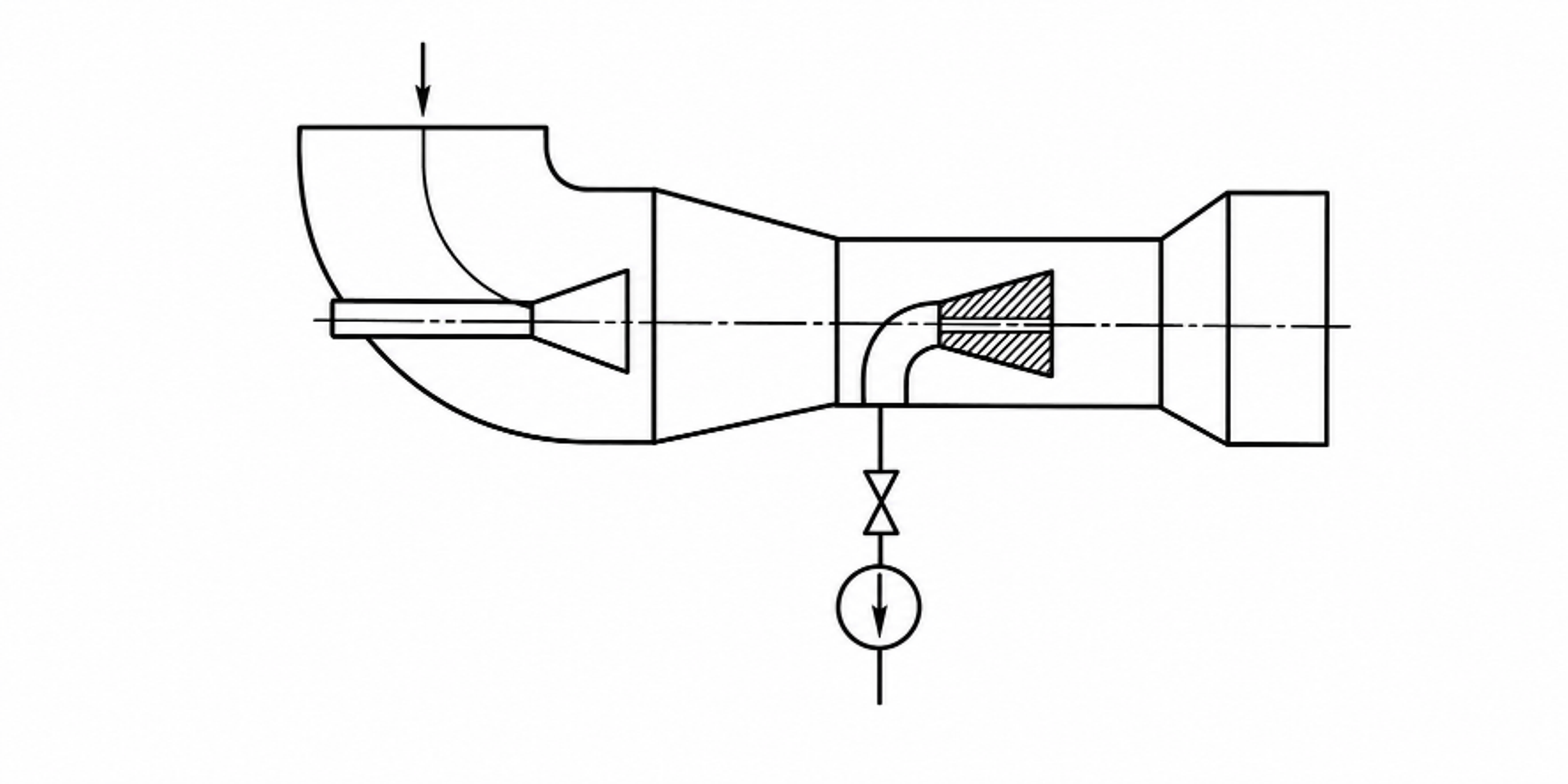
Figure 6.3. Hydrodynamic liquid degassing apparatus with a cavitation element, vacuum gas withdrawal, and diffuser [60].
A later United States patent by Kozyuk uses a cavitating restriction to nucleate dissolved gases, followed by a sequence of annular chambers, turns, and velocity reductions that promote bubble coalescence before the liquid exits. Small bubbles are deliberately converted into fewer, larger bubbles because larger bubbles separate more readily and are less likely to be carried into downstream equipment [61].
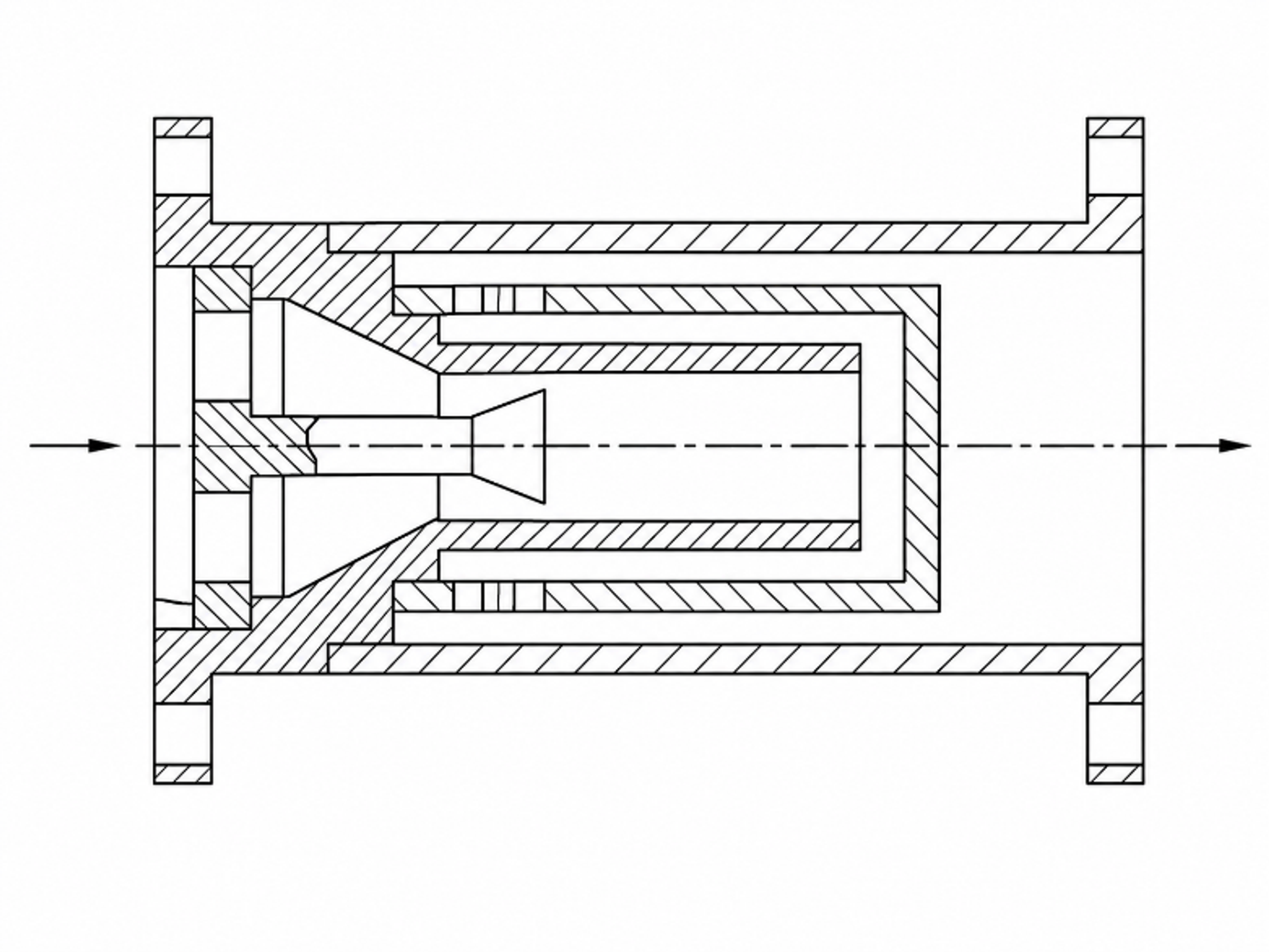
Figure 6.4. Cavitation and staged coalescence geometry for liquid degassing. [61].
Table 6.2. Functional comparison of two cavitation degasser concepts
| Design function | SU 1258460 A1 | U.S. Patent 10,159,915 B2 |
|---|---|---|
| Nucleation | Cavitation element in the working chamber | One or more local restrictions create cavities and release dissolved gases. |
| Gas growth | Gas enriched cavities expand through the diffuser and low pressure zone | Repeated changes in velocity and direction provide time for dissolved gas to enter cavities. |
| Coalescence | Conical recovery chamber and developed interface | Successive annular chambers reduce velocity and merge small bubbles. |
| Separation | Vacuum gas outlet and downstream discharge | Coalesced bubbles leave the liquid through a downstream separator or vented vessel. |
| Primary design risk | Insufficient venting or gas entrainment at high throughput | Re dissolution if pressure recovers before bubbles are physically separated. |
A complete degassing skid therefore requires a pressure controlled cavitation stage, a low velocity coalescence volume, a vent or vacuum connection, mist elimination where volatile liquids are processed, and controls that prevent air ingress or unsafe gas accumulation. Gas composition, flash point, toxicity, oxygen sensitivity, foam, and condensable vapor loading determine the required vent treatment. Performance should be reported as residual dissolved gas at a stated temperature and pressure, together with electrical energy per treated volume and the fraction of gas actually captured by the vent system.