
Technical publication
Back to publications
Industrial applications
Emerging Frontiers in Hydrodynamic Cavitation
okozyuk.com
Published
Read complete publication for whole-document Find and printing. Browser Find and native printing on this reader include only loaded content.
5 Flotation and Clarification
5.1 Bubble Particle Capture
Flotation recovery requires three probabilistic events: collision of a particle or droplet with a bubble, attachment after the intervening liquid film drains and ruptures, and retention of the aggregate against detachment forces. Hydrodynamic cavitation can contribute in two ways. It can produce a fine bubble population from dissolved gas or injected air, and it can nucleate bubbles directly on hydrophobic surfaces or within flocs. Surface nanobubbles then act as secondary collectors, increasing effective hydrophobicity and shortening induction time [23-26]. The overall collection efficiency or probability of particle capture () is governed by the collision, attachment, and detachment probabilities:
Pc is collision probability, Pa is attachment probability after collision, and Pd is detachment probability. Some literature uses different definitions, so the meaning of each term should be stated.
The phenomenological form for collision is:
This phenomenological form emphasizes that collision probability generally rises as particle diameter dp increases and bubble diameter db decreases; A and n depend on the flow regime.
Sb is bubble surface area flux and Jg is superficial gas velocity. It combines bubble size and gas rate into a useful flotation metric.
Stokes' law gives terminal rise velocity for a small isolated spherical bubble in the creeping flow regime. Larger, contaminated, or interacting bubbles require other drag correlations.
A first order flotation model relates recovery R to time t, ultimate recovery R∞, and apparent rate constant k.
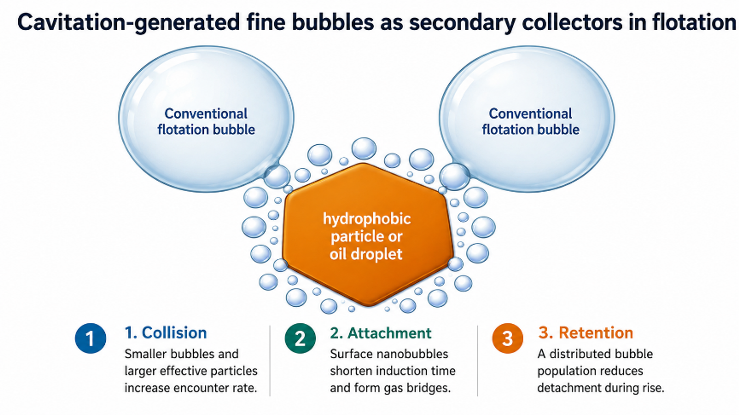
Figure 5.1. Cavitation generated fine bubbles as secondary collectors in flotation. [23-26].
5.2 Petrochemical and Refinery Wastewater
Refinery wastewater contains free oil, dispersed droplets, stable emulsions, suspended solids, corrosion products, and treatment chemicals. Free oil should be removed by gravity separators or hydrocyclones before flotation. Cavitation generated microbubbles are most useful for the remaining dispersed droplets and flocculated emulsion fragments. Bubble size should be comparable to or smaller than the target droplets to maximize encounter probability, while a coarser fraction provides buoyant lift.
Loraine and Chahine used vortex cavitating jet generators to produce a polydisperse bubble population from a few micrometres to approximately 300 µm and recover nearly neutrally buoyant crude oil droplets. The oil droplets alone rose at only 0.0147 to 0.16 mm/s in the reported 35 ppt tests; bubble oil mixtures rose at 0.3 to 1.6 mm/s, while clean water bubbles rose at 30 to 50 mm/s [27]. The mixed bubble distribution was beneficial because the smallest bubbles attached to droplets and the larger bubbles transported the complexes upward.
Independent dissolved air flotation research with microbubbles of 30-40 µm and nanobubbles of 150-350 nm showed 75% oil removal in saline water and 90% without salt under the reported nanobubble conditioning conditions [29]. A column flotation study using micro- and nanobubbles reduced residual oil to 4 mg/L in its taller column under selected conditions [30]. These results establish the importance of bubble size, salinity, emulsion chemistry, flocculation, and column hydraulics. They do not imply that cavitation alone breaks every stable refinery emulsion.
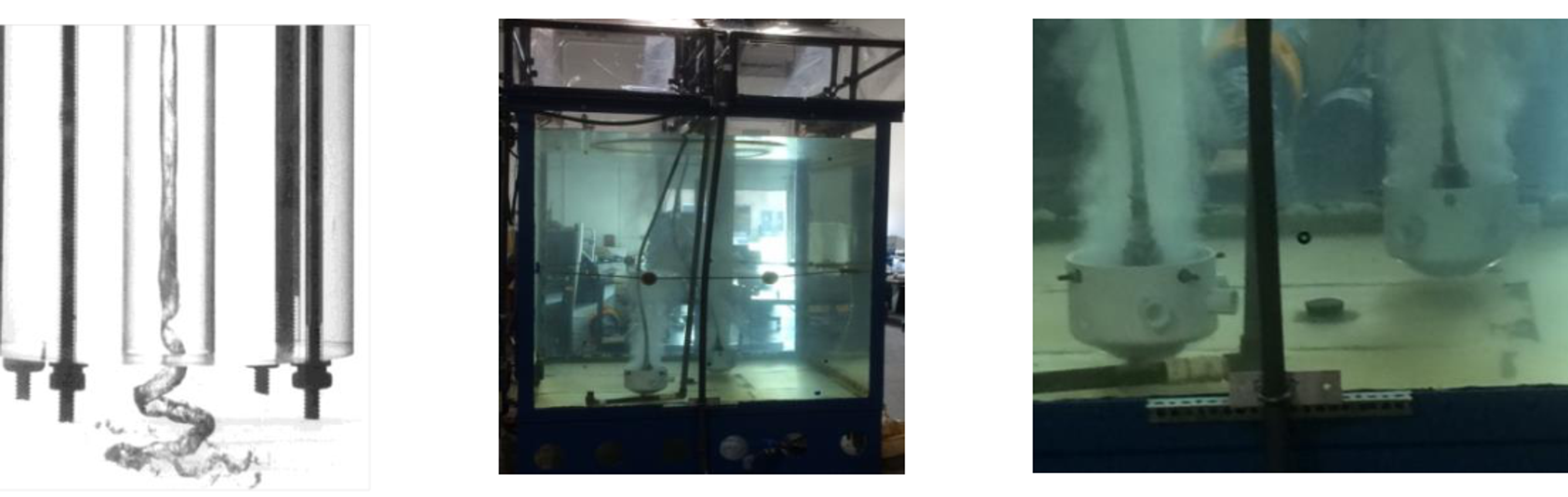
Figure 5.2. Vortex cavitation core, large test tank, and submerged cavitating bubble generators used in oil recovery experiments. [27].
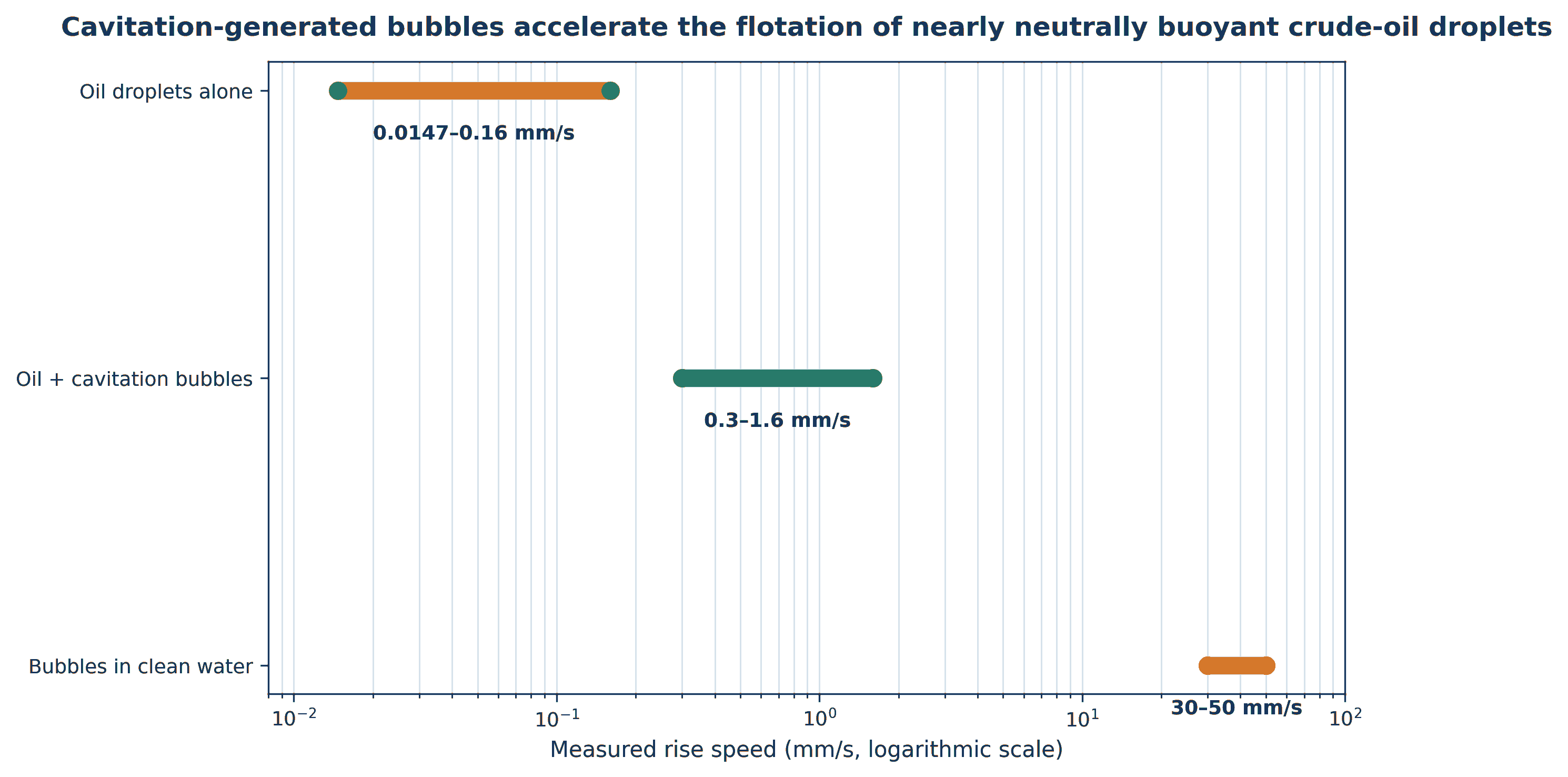
Figure 5.3. Cavitation generated bubbles accelerate the flotation of nearly neutrally buoyant crude oil droplets. [27].
5.3 Food Processing and Slaughterhouses
Food processing wastewater is frequently warm and contains fats, oils, grease, proteins, suspended tissue, starch, and cleaning chemicals. Temperature lowers water viscosity but may keep some fats liquid and emulsified. Equalization is required because pH and organic load change sharply during cleaning cycles. A practical flotation train uses coarse screening, equalization, pH adjustment, coagulation or emulsion breaking, flocculation, microbubble contact, float removal, and biological treatment.
At a 310 m³/d slaughterhouse plant, the first stage conventional DAF removed approximately 84% FOG and 72% suspended solids before biological treatment [28]. This evidence is not specific to hydrodynamic cavitation bubble generation, but it defines the pretreatment duty that a CAF system must equal or exceed. Cavitation can reduce the compressed air and saturation vessel requirements when self-aspiration is effective, yet the total process economics must include pump energy, coagulant demand, float handling, odor control, and cleaning of the aerator.
5.4 Pulp and Paper Mills
Whitewater contains recoverable fibers, fines, clay or calcium carbonate filler, sizing agents, dissolved and colloidal substances, and microorganisms. Flotation can return fibers to the process, reduce solids loading on savealls and biological treatment, and support water circuit closure. The fibers and fillers are often readily floatable after polymer conditioning, but aluminum salts, anionic trash, and variable furnish chemistry strongly affect performance.
Furukawa's dissolved air flotation study showed that pulp type, filler fraction, aluminum sulfate, and polyelectrolyte selection determine flotation velocity and clarity [31]. A long term industrial field trial in a mill using 100% recovered paper demonstrated that an optimized polyaluminum salt/polyamine treatment improved DAF removal under high contaminant load and permitted greater circuit closure [32]. Cavitation spargers can be inserted as the bubble generation stage, but the same furnish specific coagulation and retention chemistry remains necessary.
5.5 Tanneries and Textile Processing
Tannery wastewater can contain hair, flesh, protein, sulfide, chromium bearing solids, fat, and suspended lime. Textile wastewater contains dyes, surfactants, salts, fibers, and sizing chemicals. Flotation is most effective after the target is converted into a hydrophobic precipitate or floc. Sulfide and volatile compounds favor enclosed gas handling, while chromium bearing solids should be recovered rather than dispersed by aggressive aeration.
Dafnopatidou and Lazaridis reported dye removal above 97% from selected simulated and industrial textile effluents when dissolved air or dispersed air flotation was combined with appropriate collectors, flocculants, and polyelectrolytes [33]. The study also warned that full scale confirmation was needed. A cavitation contactor may reduce bubble size and improve contacting, but it cannot substitute for charge neutralization and selective chemistry.
Table 5.1. Cavitation flotation applications and pretreatment requirements
| Sector and target | Typical conditioning before bubble contact | Primary separator duty | Important caution |
|---|---|---|---|
| Refinery: dispersed crude, fuels, free oil residual | Gravity free oil removal, emulsion breaker, pH and polymer as needed | Lift droplet floc aggregates; skim oil rich float | Stable surfactant emulsions may require substantial chemistry |
| Food/slaughterhouse: FOG, blood, proteins | Screening, equalization, pH control, coagulant/polymer | Reduce FOG, TSS, BOD/COD load before biology | Odor, warm emulsions and variable cleaning chemistry |
| Pulp and paper fibers, fines, filler | Furnish specific cationic polymer or coagulant | Recover fiber and clarify whitewater for reuse | Aluminum salts and dissolved/colloidal substances alter response |
| Tannery: hair, protein, chromium solids | Segregation, sulfide control, precipitation and flocculation | Remove floatable solids and precipitates | Do not strip untreated sulfide; segregate chromium bearing sludge |
| Textile: dye aggregates and fibers | Collector, surfactant, electrolyte and polyelectrolyte optimization | Float dye flocs and suspended fibers | Residual color and salinity may still require oxidation or membranes |
Table 5.2. Representative bubble size regimes and their flotation roles
| Nominal size range | Primary role | Advantages | Limitations |
|---|---|---|---|
| <1 µm, often termed nanobubbles | Surface activation and secondary collection | Long residence, nucleation on hydrophobic surfaces, reduced induction time | Measurement uncertainty; limited direct buoyancy; stability depends on chemistry |
| 1-20 µm | Attachment to fine particles and droplets | Very high interfacial area and encounter frequency | Slow rise and possible loss with clarified water |
| 20-100 µm | Conventional DAF/CAF lifting bubbles | Good compromise between area and rise velocity | Coalescence and dissolution depend on saturation and surfactants |
| 100-300 µm | Bulk lift and circulation in polydisperse systems | Higher rise velocity; can entrain fine bubble particle complexes | Lower area per gas volume; greater detachment risk for weak aggregates |
5.6 Fine Mineral Flotation and Dual Bubble Systems
Fine mineral particles are difficult to recover because their inertia is too small to produce frequent collisions with conventional millimeter size bubbles. Under otherwise similar hydrodynamic conditions, collision probability scales approximately with the square of the particle to bubble diameter ratio. Reducing bubble size and forming selective particle aggregates are therefore complementary strategies. Hydrodynamic cavitation can contribute both effects by generating microbubbles and by promoting bubble attachment to hydrophobic surfaces [25,26,56].
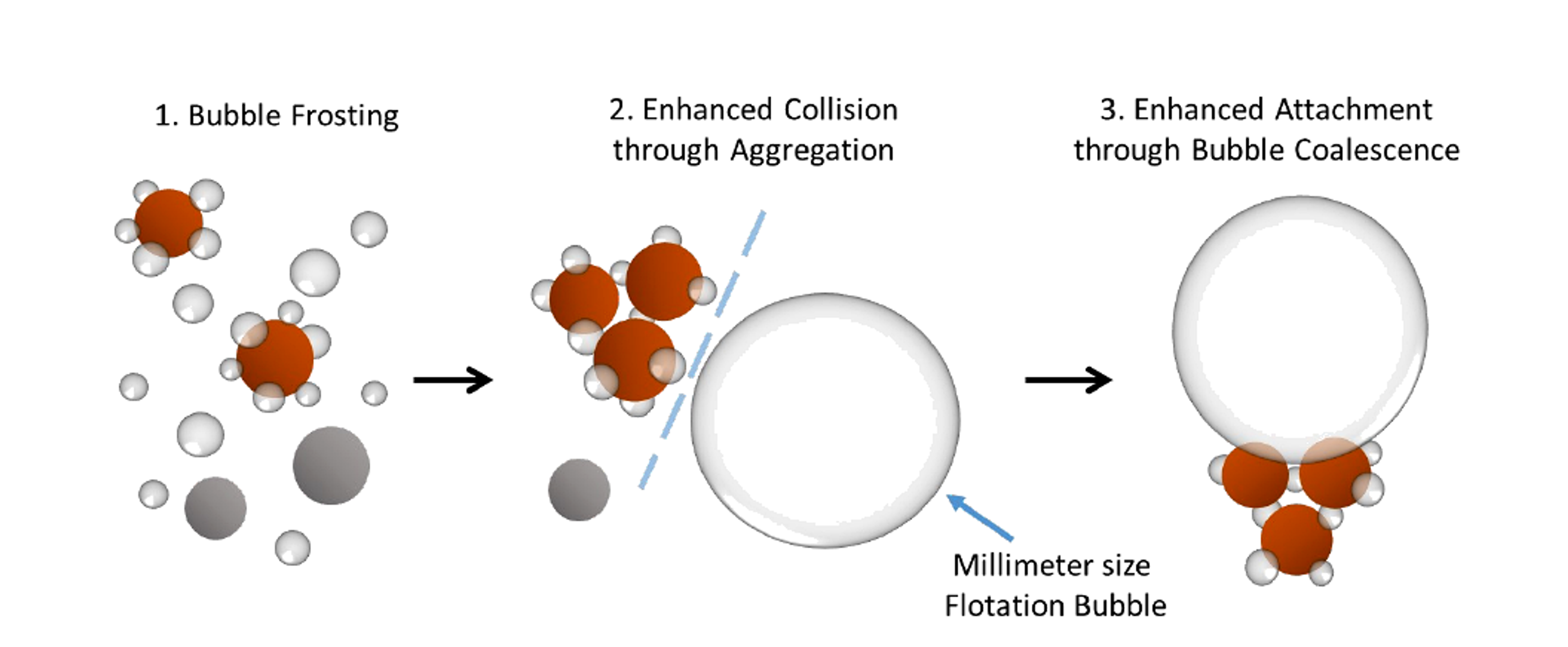
Figure 5.4. Mechanism proposed for hydrodynamic cavitation enhanced fine particle flotation: bubble frosting, aggregation, and microbubble assisted attachment. [56].
The University of Alberta thesis separates the enhancement into three steps. First, cavitation microbubbles preferentially nucleate or remain on hydrophobic particle surfaces, a phenomenon described as bubble frosting. Second, surface microbubbles bridge particles and increase their apparent size, raising collision probability. Third, a conventional flotation bubble attaches more readily to a microbubble covered aggregate because the intervening liquid film drains rapidly and local coalescence provides an attachment pathway. The measured benefit was much stronger for hydrophobized silica than for hydrophilic silica, indicating that cavitation can improve selectivity as well as recovery [56].
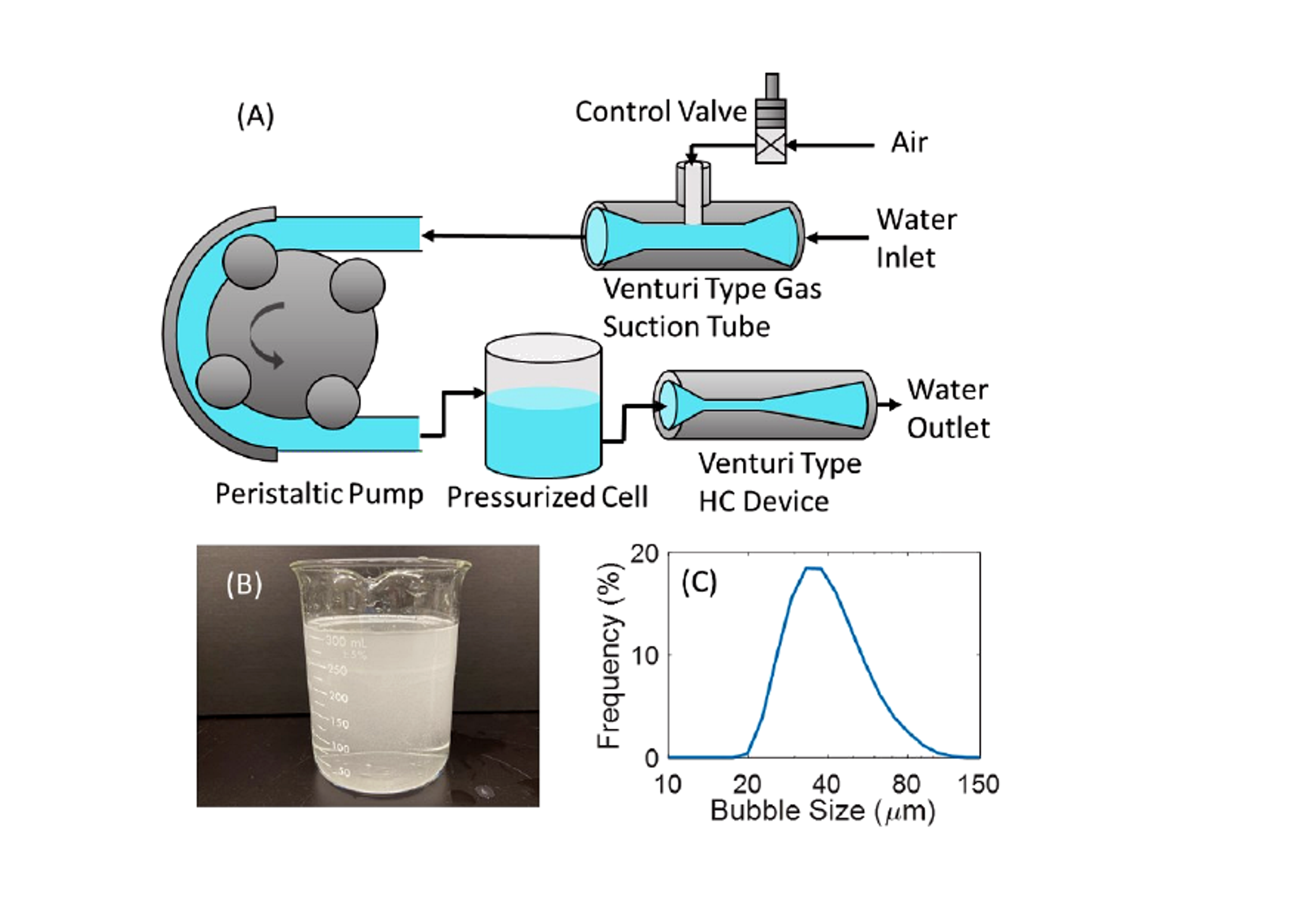
Figure 5.5. Auto gas suction Venturi loop, visible microbubble dispersion, and measured bubble size distribution. [56].
Gas injection location is a decisive design variable. Injection upstream of a Venturi may fragment conventional bubbles but can suppress the formation of a distinct cavitation microbubble population. Injection downstream can preserve both populations and create a dual bubble system. In the reported molybdenite and silica tests, upstream injection reduced selectivity through entrainment, whereas downstream injection allowed recovery and concentrate grade to be balanced by gas rate and injection distance [56]. Commercial cavitation tube spargers apply the same principle in column flotation and feed pre aeration circuits, where recycle slurry, process air, and a cavitating restriction are combined to create a dense fine bubble plume [25,26,67].
5.7 Integrated Coagulation and Flotation for Natural Organic Matter
Hydrodynamic cavitation can integrate rapid coagulant dispersion and microbubble generation in a compact treatment step. Pagan et al. injected ferric chloride at the throat of a continuous flow Venturi system and floated the destabilized humic substances. Five divergent angles were compared while throat diameter and converging geometry were held constant [57].
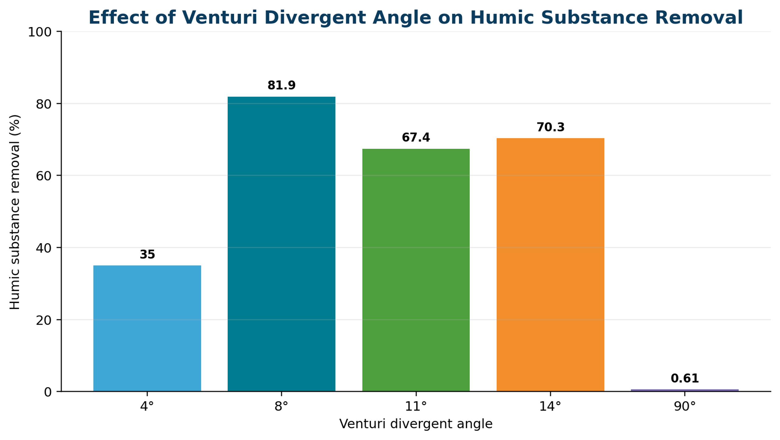
Figure 5.6. Effect of Venturi divergent angle on humic substance removal. [57].
The 8° divergent angle produced the best reported removal, 81.9%, because it combined stable microbubble generation with effective pressure recovery and rapid coagulant distribution. Comparable performance in the reference dissolved air flotation apparatus required at least 30% saturated recycle water, whereas the cavitation system operated continuously without an external saturation vessel. The result shows that geometry controls not only cavitation intensity but also bubble residence, coagulant mixing, and the hydrodynamic pathway to separation [57].
is the humic substance removal efficiency, C₀ is the initial concentration, and Cₜ is the concentration after the specified coagulation and flotation period.
Translation to drinking water requires additional validation. Humic acid concentration, molecular character, alkalinity, pH, coagulant dose, residual iron, floc strength, downstream filtration, disinfection byproduct formation potential, and sludge handling must all be evaluated. The cavitation unit should be considered an integrated contactor whose success depends on the complete solids separation train, not on removal measured immediately after the Venturi alone [57].