
Technical publication
Back to publications
Industrial applications
Emerging Frontiers in Hydrodynamic Cavitation
okozyuk.com
Published
Read complete publication for whole-document Find and printing. Browser Find and native printing on this reader include only loaded content.
3 Cooling Water and Commercial Aquatic Systems
3.1 Treatment Objectives and Process Architecture
Open recirculating cooling towers and evaporative condensers continuously concentrate dissolved salts because essentially pure water is lost by evaporation while minerals remain in the circulating inventory. The operating program must simultaneously control mineral scale, corrosion, suspended solids, algae, bacteria, and microbiologically influenced corrosion while preserving heat transfer performance. Conventional programs use scale inhibitors, corrosion inhibitors, oxidizing or nonoxidizing biocides, dispersants, pH control, blowdown, and filtration. Controlled hydrodynamic cavitation systems were developed as nonchemical or reduced chemical side stream alternatives [7-12].
A practical cooling water installation is a treatment train rather than an isolated cavitation chamber. One side stream passes basin water through the cavitation device, while another removes precipitated mineral solids and environmental debris through a cyclone, automatic screen, sand filter, bag filter, or equivalent separator. Conductivity or constituent concentration controls blowdown, and corrosion coupons, bacterial counts, deposit inspection, heat transfer measurements, and makeup water chemistry provide verification. Reviewed field reports show that solids removal becomes increasingly important as cycles of concentration rise [7-13].
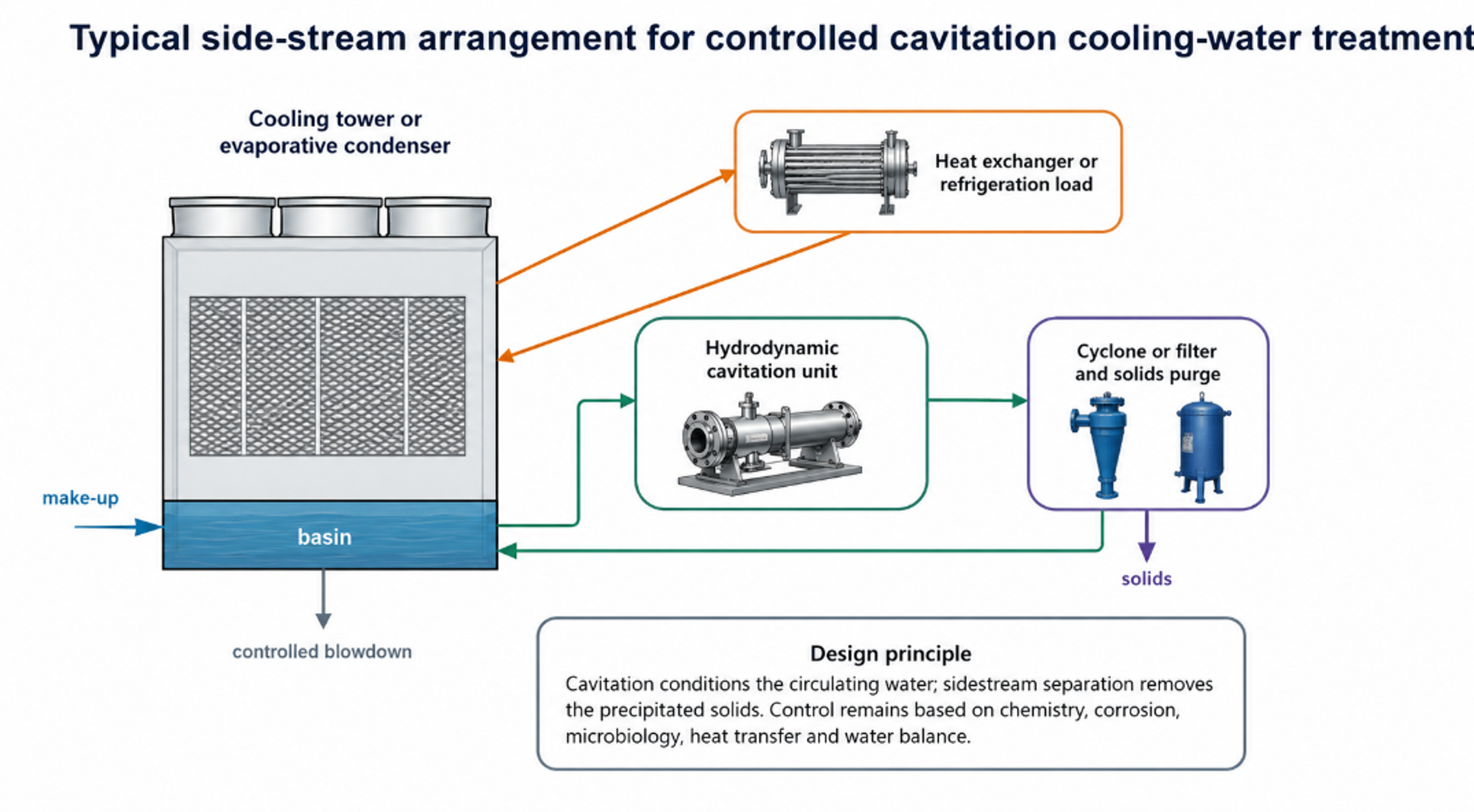
Figure 3.1. Typical side stream arrangement for controlled cavitation cooling water treatment. [7-13].
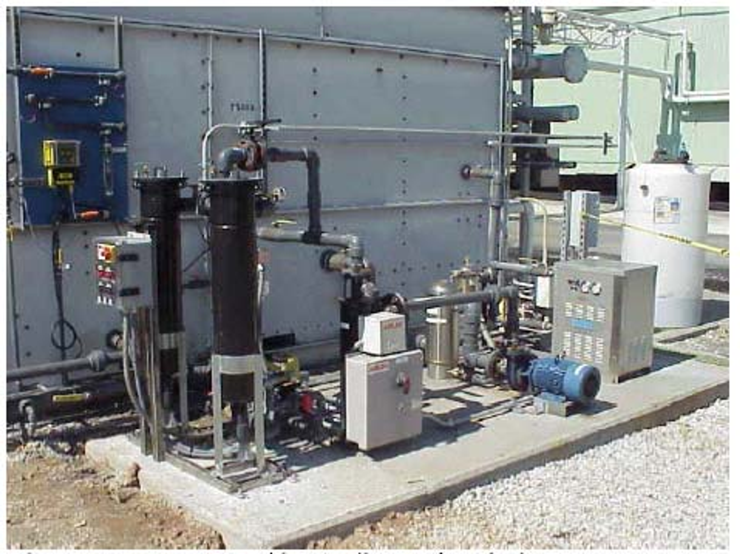
Figure 3.2. Field installed hydrodynamic cavitation cooling water skid with pumps, cavitation unit, cyclone, bag filtration, controls, and piping. [8].
3.2 Cooling Tower Water Balance and Concentration Control
Cycles of concentration compare a conservative dissolved constituent in the circulating water with the same constituent in the makeup water. Conductivity is convenient but can underestimate the true concentration factor when calcium carbonate and other salts precipitate. The Alcoa comparison therefore concluded that sodium, magnesium, potassium, and sulfate ratios were more reliable at high cycles than conductivity alone [8].
and are concentrations of a conservative constituent in circulating and makeup water. The overall water balance for the system is governed by the mass flow rates:
M is makeup flow, E is evaporation, B is blowdown, and includes drift and other measured losses.
Assuming the selected constituent remains fully soluble and undergoes no precipitation or chemical reaction, the steady-state blowdown requirement can be approximated by:
This simplified steady-state expression quantitatively illustrates how operating at elevated cycles of concentration effectively reduces blowdown volume.
3.3 Scale Control by Gas Release and Bulk Crystallization
The central scale control concept is to promote calcium carbonate formation in the bulk water, where particles can be removed, rather than on the hottest heat transfer surface. Pressure reduction can release dissolved carbon dioxide and alter carbonate equilibrium; local heating and intense mixing can accelerate nucleation; recirculated precipitate provides seed surface. The overall bicarbonate decomposition is represented by the bicarbonate equilibrium below. Chemistry is reversible and depends on pH, alkalinity, calcium activity, ionic strength, temperature, and gas exchange.
This expression represents coupled carbonate equilibria rather than a single elementary reaction.
The Langelier Saturation Index compares measured pH with the calculated calcium carbonate saturation pH, pHs. A slightly positive LSI indicates a scale forming tendency but does not identify where precipitation will occur.
Kim and coworkers investigated a semi batch hyperkinetic vortex crystallization process for calcium rich electronics wastewater. At stable operation, the feed calcium averaged 162.6 mg/L, and the effluent averaged 48.5 mg/L; removal ranged from 62.8 to 76.1%, with a mean of 70.2%. Cavitation produced smaller, more spherical calcite particles with greater specific surface area, supporting clarification and reducing the likelihood of tenacious deposition in piping [13]. This result supports the bulk crystallization mechanism, although the wastewater chemistry and sodium carbonate dosing differ from ordinary cooling tower water.
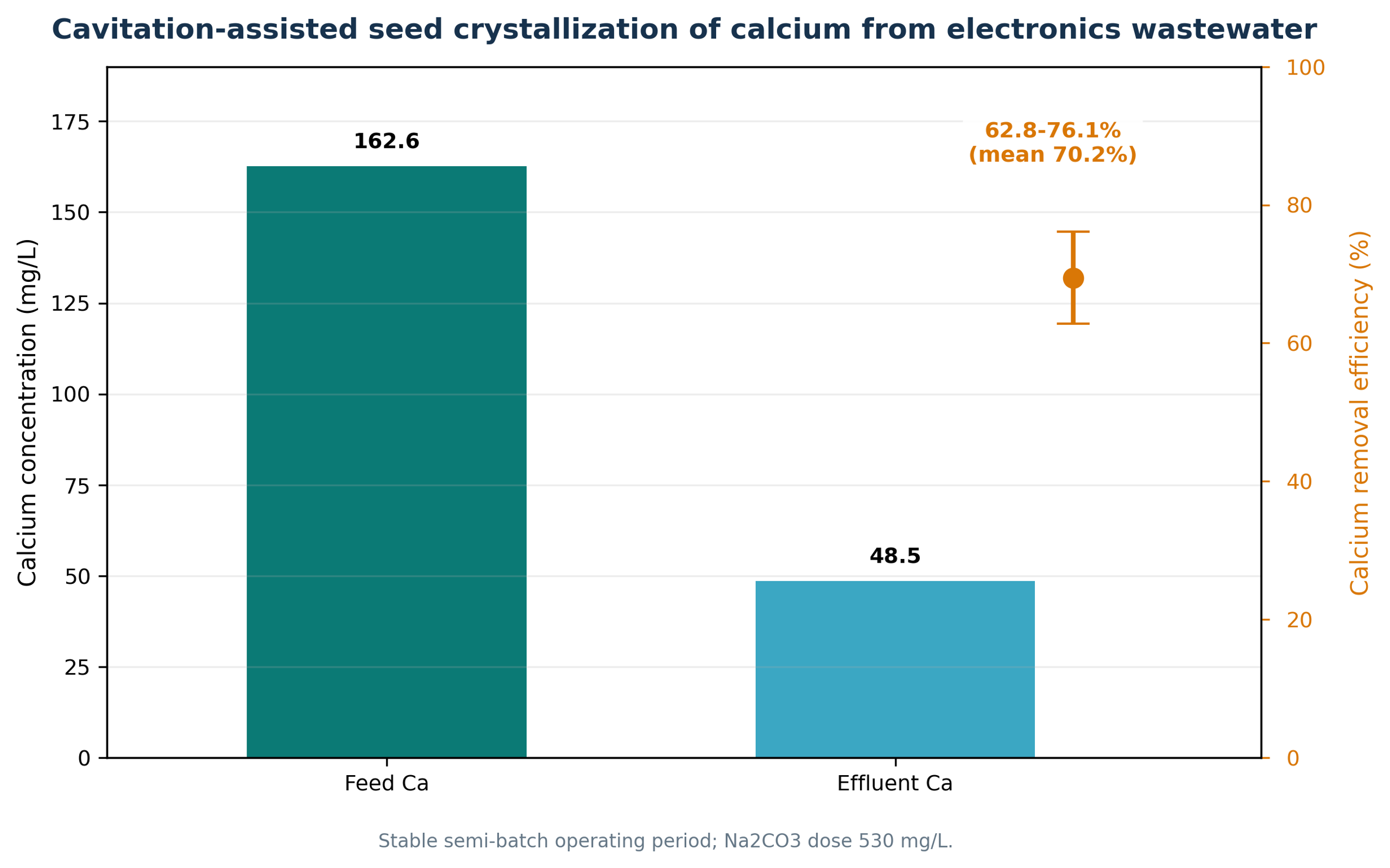
Figure 3.3. Cavitation assisted seed crystallization of calcium from electronics wastewater. [13].
3.4 Microbiological and Corrosion Control
Microorganisms passing through the active cavitation zone are exposed to pressure fluctuations, shear, microjets, and transient radicals. This is a pass through treatment. Unlike chlorine, bromine, ozone residual, or another persistent biocide, cavitation does not automatically protect remote dead legs, drift eliminators, fill surfaces, or established biofilms. This distinction is particularly important for Legionella risk management. In the automotive field study, total heterotrophic plate count stabilized near 10⁴ CFU/mL during a two month trial without chemical disinfectant, and no Legionella was detected in either the preceding chemical period or the cavitation trial. The authors stated that longer testing and formal field verification were required and that the process may not be appropriate as the sole disinfectant in every system [7].
Corrosion response is similarly conditional. Cavitation may remove carbon dioxide, reduce biofilm, avoid corrosive chemical shocks, and maintain alkaline water. Conversely, higher cycles increase dissolved solids and scaling indices; oxygen remains present; and mechanically generated solids can create under deposit conditions if not removed. The automotive trial reported copper and mild steel corrosion rates equivalent to or better than the chemical baseline, but galvanized steel required attention [7]. The six month Alcoa comparison found the chemical tower had the lowest average corrosion rate, although the nonchemical rates remained within the study's industry criteria [8]. These results are not contradictory: they demonstrate that source water hardness, orthophosphate, metallurgy, deposit removal, and operating cycle determine the result.
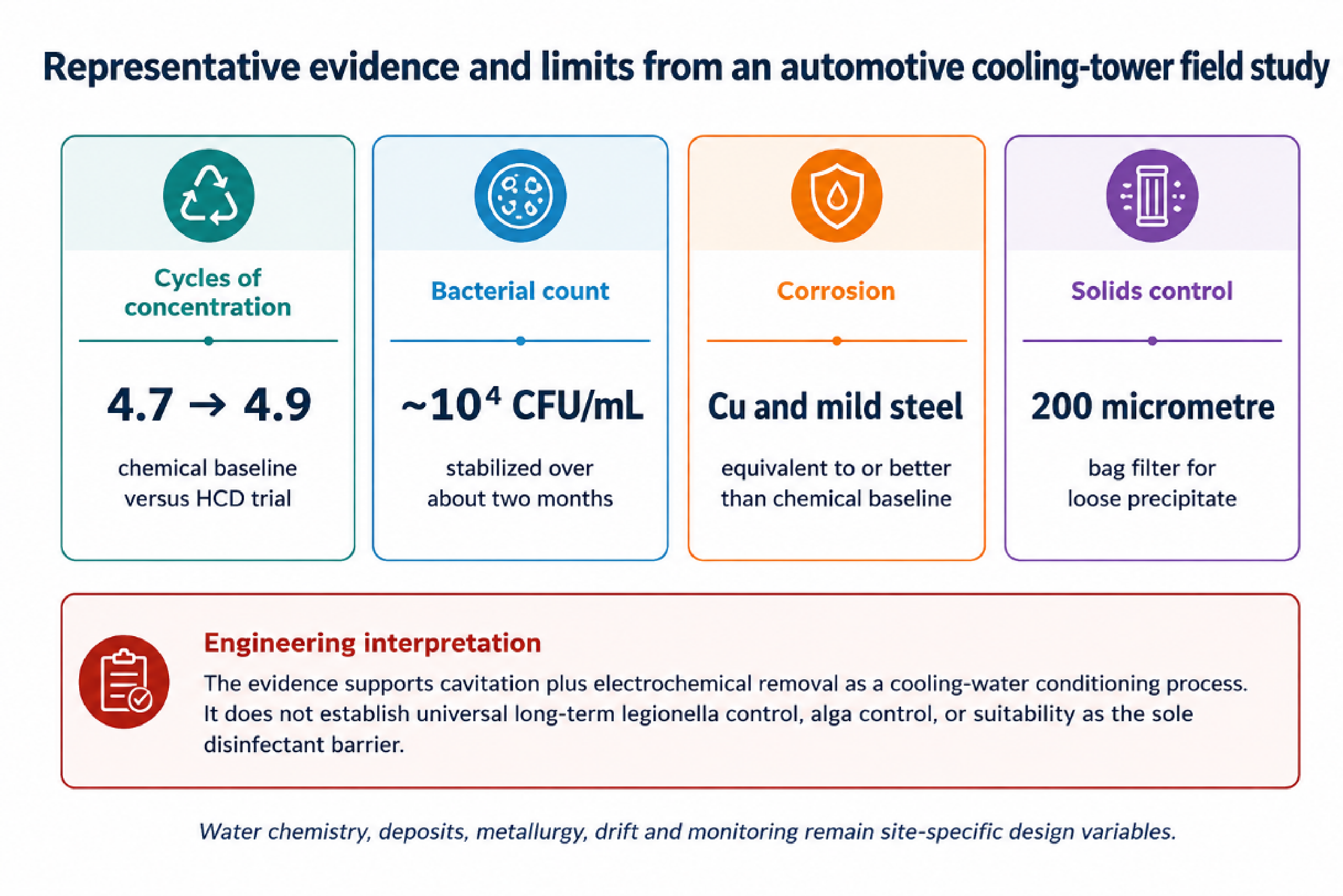
Figure 3.4. Representative evidence and limits from an automotive cooling tower field study. [7].
3.5 Field Evidence and Design Conclusions
Table 3.1. Selected cooling water evidence from the reviewed sources
| Source and setting | Reported result | Interpretation and limitation |
|---|---|---|
| Automotive test facility, approximately 7000 gal system [7] | Bacterial count near 10⁴ CFU/mL; CoC 4.9 vs 4.7 chemical baseline; Cu and mild steel corrosion equivalent or better | Two month trial; no persistent residual; longer Legionella and heat transfer verification needed |
| Three nominally identical Alcoa evaporative coolers [8] | HDC and pulsed power towers gave better planktonic and sessile microbial control; HDC coupons remained below 10⁶ CFU/cm² | Chemical tower had best corrosion; water savings were not statistically different at identical control settings; side stream solids removal was decisive |
| Heineken evaporative condensers, ISPT project [14] | Visual scaling equal to or less than chemical treatment; chemical analyses indicated successful corrosion and microbial control; reported payback below two years | Project summary rather than a fully detailed peer reviewed trial |
| Electronics wastewater seed crystallization unit [13] | Mean calcium removal 70.2%; smaller and more spherical calcite after cavitation | Strong evidence for bulk crystallization, but chemistry included Na₂CO₃ dosing and differs from cooling tower makeup |
| Commercial and government reports [9–12] | Case histories report chemical reduction, higher cycles and water savings | Performance data quality varies; independent verification and local compliance remain essential |
| Cooling water design conclusion. Controlled hydrodynamic cavitation is best specified as one component of a side stream conditioning system. A robust design includes solids separation, chemistry control, corrosion verification, microbiological verification, basin cleaning, drift management, and a contingency biocide strategy. It should not be presented as a universal chemical free replacement without site specific validation. |
|---|
3.6 Commercial Aquatic Water Systems
Commercial swimming pools and spas present a related but more tightly regulated recirculating water problem. The objective is not to eliminate disinfectant, but to reduce the load placed on the chemical program while maintaining a continuously verifiable disinfectant residual, acceptable combined chlorine, clear water, stable pH, adequate filtration, and pathogen control. An inline cavitation device is therefore an adjunct to circulation, filtration, heating, chemical feed, and code compliant disinfection rather than a substitute for them [52,66].
The AquaRev engineering assessment describes a passive inline device installed in an existing return loop. The reported laboratory and field results include a 36% reduction in combined chlorine, a 54% reduction in chlorine demand, and operational reductions in salt, acid, carbon dioxide, evaporation loss, and energy use. These results are specific to the evaluated device and test program and should be treated as qualification targets for facility verification rather than universal guarantees across pool chemistry, bather load, temperature, or hydraulic conditions [52].
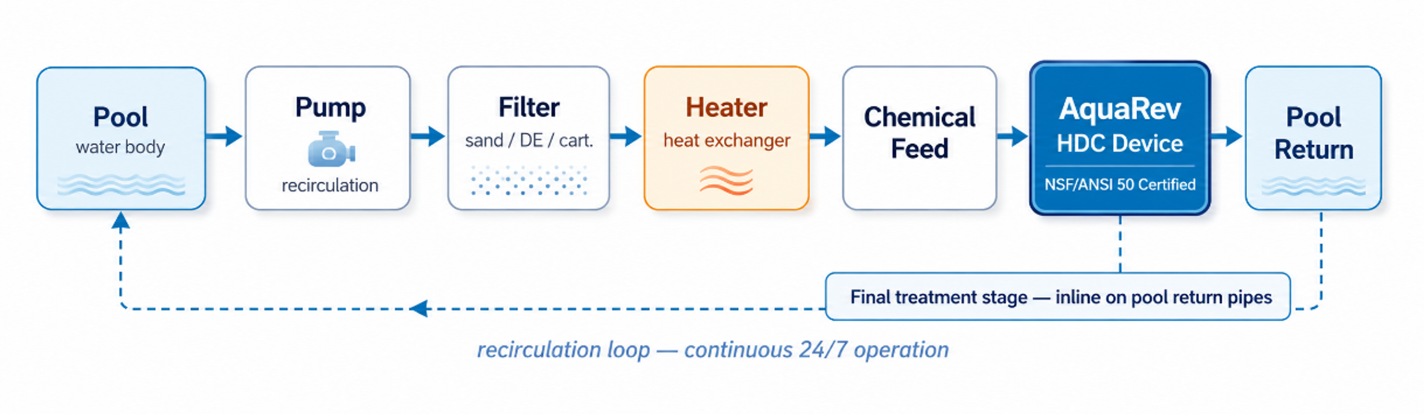
Figure 3.5. Typical integration of a passive hydrodynamic cavitation device into a commercial pool recirculation loop.
Hydraulic exposure is best expressed by treated turnovers rather than by elapsed clock time alone. If the device processes a flow Q for an evaluation period T in a pool or basin of volume V, the nominal number of treated turnovers is:
Nₜ is the nominal treated turnover count, Q is the device flow rate, T is the evaluation period, and V is the recirculating water volume. This metric does not imply perfect mixing, so tracer testing or a verified circulation model is required for large or irregular basins.
A defensible commissioning trial maintains comparable occupancy, temperature, filtration rate, disinfectant control logic, and weather exposure before and after installation. At minimum, the trial should track free and combined chlorine, oxidation reduction potential, pH, alkalinity, cyanuric acid where applicable, turbidity, makeup water, evaporation, filter backwash, chemical consumption, pump power, microbial indicators, and complaints related to odor or irritation. Any reduction in chemical use must be accompanied by evidence that the required disinfectant residual and microbial barriers were maintained [52,66].
Table 3.2. Verification framework for commercial aquatic systems
| Verification category | Measurements | Acceptance principle |
|---|---|---|
| Hydraulics | Device flow, inlet and outlet pressure, turnover count, bypass position | Operate inside the qualified pressure and flow window without compromising code required recirculation. |
| Water chemistry | Free and combined disinfectant, pH, alkalinity, cyanuric acid, conductivity, calcium hardness | Compare with a matched baseline and maintain all regulatory limits. |
| Water quality | Turbidity, particle counts, visual clarity, odor, surface deposits | Improvement must not be achieved by weakening filtration or disinfectant control. |
| Microbiological performance | Heterotrophic counts and facility specific pathogen monitoring | Treat cavitation as a supplementary barrier unless independent validation establishes a primary disinfection claim. |
| Resource use | Chemical mass, makeup and drain water, pump electricity, heating energy | Normalize by occupancy, operating hours, weather, and treated water volume. |