
Technical publication
Back to publications
Industrial applications
Emerging Frontiers in Hydrodynamic Cavitation
okozyuk.com
Published
Read complete publication for whole-document Find and printing. Browser Find and native printing on this reader include only loaded content.
10 Cavitating Jet Cleaning and Surface Treatment
10.1 Cleaning Mechanism and Nozzle Operating Window
A submerged cavitating jet issues from a nozzle into water and forms a vapor cloud or vortex cavity. The cavity convects toward the target, fragments into clouds, and collapses as pressure recovers or the jet impinges on the surface. Collapse generates pressure pulses, microjets, and fluctuating shear that undermine deposits. Relative to a solid high pressure jet, a properly tuned cavitating jet can provide strong deposit removal at lower stagnation pressure and distribute impact over a broader footprint [1,38-42].
Cleaning performance depends on nozzle geometry, pressure, flow, cavitation number, standoff distance, traverse speed, angle, water temperature, target curvature, deposit adhesion, and coating properties. There is usually an optimum standoff: too close and the cavity has not developed; too far and collapse occurs before the target. The optimum shifts with backpressure, nozzle scale, and gas content.
is idealized jet velocity and is discharge coefficient.
is jet dynamic pressure. Cavitation collapse can create local transient pressures much higher than the mean dynamic pressure.
The dimensionless standoff ratio uses target distance S and nozzle diameter .
is specific cleaning energy per cleaned area; Aclean is verified area reaching the cleanliness criterion.
RA is the areal cleaning rate and should be reported with deposit type, thickness, substrate, and damage criterion.
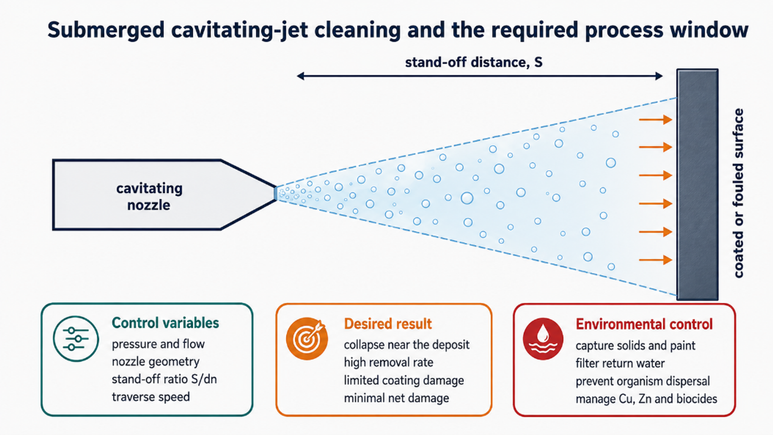
Figure 10.1. Submerged cavitating jet cleaning and the required process window. [70].
10.2 Marine Vessel Maintenance
Underwater cleaning allows hulls, propellers, rudders, bow thrusters, sea chests, and appendages to be serviced without full dry docking. The operational benefit can be substantial when fouling raises drag and fuel consumption. Cavitation cleaning is particularly attractive where the objective is to detach barnacles and soft fouling while preserving an antifouling coating.
An early CAVIJET program reported laboratory removal rates of 900-1030 ft²/h from heavily fouled submerged panels using 1/4 in. or dual 1/8 in. nozzles at 1500-2000 psi [40]. Modern studies place equal emphasis on coating damage and biosecurity. Bloecher et al. found high cleaning efficacy for both cavitation and high pressure cleaning on aquaculture nets, but a single high pressure treatment caused up to 53% coating degradation compared with 2% for cavitation [38]. Cleaning efficacy alone is therefore insufficient; coating mass loss, surface roughness, tensile strength, debris size distribution, and contaminant release should also be measured.
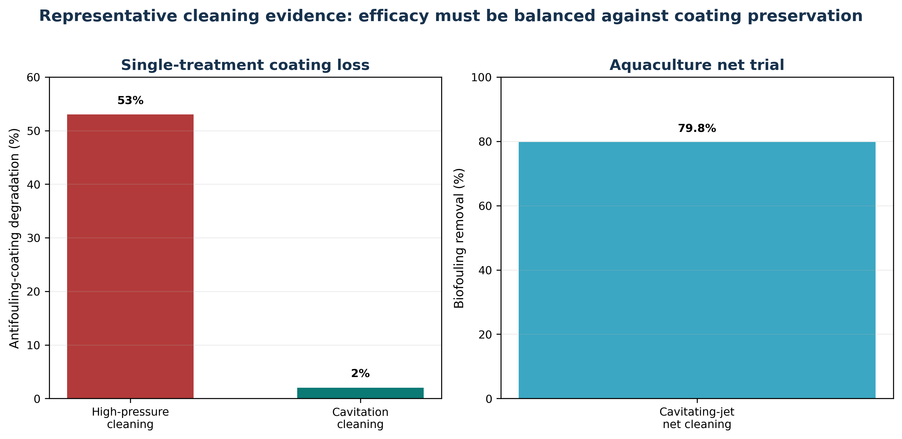
Figure 10.2. Representative cleaning evidence: efficacy must be balanced against coating preservation. [38].
10.3 Offshore Energy Infrastructure
Oil platforms, wind turbine foundations, risers, subsea pipelines, mooring chains, intake structures, and remotely operated vehicle components accumulate marine growth and mineral scale. Cavitating jets can be mounted on crawler, ROV, or diver held tools. Offshore design adds constraints absent from a laboratory panel: large ambient pressure, currents, complex curvature, poor visibility, remote power, hose losses, corrosion, and debris recovery.
The system should be qualified against representative coatings and cathodic protection components. High pressure cleaning can expose steel or damage thermal spray aluminum, elastomers, composite wraps, subsea cables, and anodes. Cavitation intensity should be sufficient to remove the deposit but not to initiate pitting or delamination. For inspection cleaning, a lower intensity pass may be preferable to full surface preparation.
10.4 Aquaculture Net Boxes
Aquaculture nets must remain permeable to maintain oxygen supply and waste transport. In situ cleaning avoids net exchange, but detached biofouling can enter the cage, expose fish to pathogens, and spread nonindigenous organisms. Copper- or zinc containing antifouling coatings create an additional contaminant pathway. Measurements from hydroblasting effluent have shown high copper and zinc concentrations, demonstrating the need for capture and management rather than assuming that underwater cleaning is pollution free [42].
A cavitation cleaner should therefore be integrated with suction, collection skirts, filtration, or controlled cleaning zones where practical. Operating procedures should address fish behavior, noise, suspended solids, dissolved oxygen, disease transmission, and cleaning frequency. Frequent low damage cleaning before heavy fouling develops may be superior to infrequent aggressive cleaning.
Table 10.1. Cavitation jet cleaning applications and qualification criteria
| Asset | Cleaning target | Qualification metric | Environmental control |
|---|---|---|---|
| Ship hull and propulsor | Barnacles, slime, calcareous fouling | Removal rate, coating loss, roughness, propeller balance | Debris capture, invasive species protocol, paint particle control |
| Offshore platform and riser | Dense marine growth, scale, inspection access | Standoff tolerance, curvature coverage, substrate damage | ROV collection, turbidity and coating debris management |
| Subsea pipeline and chain | Biofouling, mineral deposit, corrosion product scale | Coverage, residual thickness, pitting inspection | Prevent redistribution to sensitive habitat |
| Aquaculture net | Hydroids, algae, mussels, biofilm | Net permeability, coating loss, tensile strength, fish exposure | Suction or collection, Cu/Zn analysis, and pathogen control |
10.5 Nozzle Design, Tool Wear, and Surface Qualification
Cavitating nozzle design follows two broad strategies. A high discharge coefficient design preserves jet momentum and relies mainly on hydrodynamic impact. A cavitation amplifying design deliberately introduces sharp edges, deflectors, resonant chambers, or internal disturbances to increase vapor cloud formation. The preferred design depends on deposit strength, target standoff, ambient pressure, available pump power, and the allowable damage to the substrate [69].
The nozzle is a consumable erosion component. Surface finish, throat geometry, material hardness, corrosion resistance, and internal stress concentration determine service life. The reviewed oil and gas literature describes bronze as suitable for short prototype service and more resistant materials for severe duty. Modern systems may use hardened steel, tungsten carbide, ceramic, or replaceable inserts. Qualification should measure nozzle mass loss and geometry drift because throat wear changes both flow and cavitation intensity [25,69].
Cleaning acceptance must include the condition of the underlying surface. Deposit removal rate alone is insufficient when the asset carries a protective coating, fatigue sensitive weld, polymer liner, or biological containment requirement. A practical test matrix varies pressure, standoff, traverse speed, nozzle angle, and number of passes while measuring residual fouling, coating loss, roughness, erosion depth, captured debris, and water quality. The BSEE cavitating water jet program provides an early government documented example of this qualification approach for marine growth removal [64].