
Technical publication
Back to publications
Industrial applications
Design and Operating Principles of Rotor-Stator Mixers
okozyuk.com
Published
Read complete publication for whole-document Find and printing. Browser Find and native printing on this reader include only loaded content.
5. Single Stage and Multistage Mixers
A single stage mixer has one localized zone of hydromechanical interaction between rotor and stator. Multiple perforations in one stator screen do not constitute multiple processing stages. The relatively simple design reduces holdup volume, facilitates inspection, maintenance, and cleaning, and often provides adequate intensity for wetting, mixing, and moderate dispersion. Actual hydraulic pressure losses and shear stress distributions are nevertheless determined by the geometry of the working elements.
In a multistage mixer, hydromechanical treatment zones are positioned sequentially along the process flow. This allows progressive processing: an initial coarse stage precedes more restrictive stages, reducing the mechanical load imposed by large agglomerates on the final generator. Stages may be arranged along the machine axis or as concentric cylindrical elements. The term stage must therefore be interpreted within the architecture of the specific machine. IKA describes its DISPAX-REACTOR® DR 2000 as a three stage inline disperser, whereas the rotor-pulsation literature describes both concentric and disk-type assemblies [2, 5, 6, 7, 15].
Adding stages exposes the material to more deformation events but also increases hydraulic resistance, holdup volume, localized heat generation, abrasive wear, and the complexity of cleaning and sterilization in place (CIP/SIP). Stages mounted on one shaft have the same angular velocity but different tip speeds if their active radii differ. Similarly, a restrictive fine dispersion stage does not necessarily dissipate the same fraction of input power as the initial stage. Stage count is therefore an important design variable, but not a universal measure of overall hydromechanical processing efficiency.
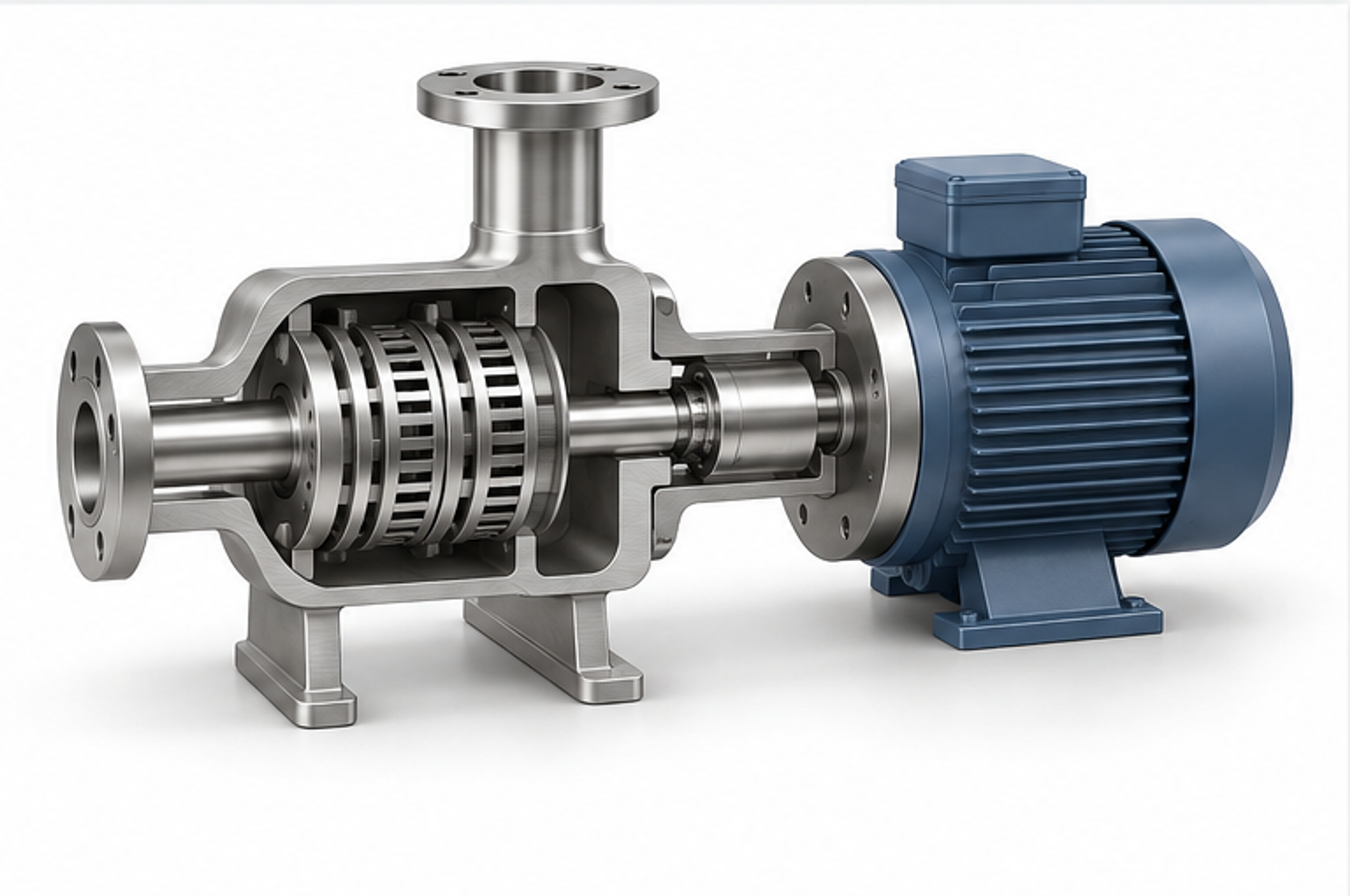
Figure 5.1. Simplified illustrative reconstruction of a multistage rotor-pulsation apparatus with an enclosed processing chamber. RU 55302 U1. [7].
Table 5.1. Comparison of single-stage and multistage designs
| Characteristic | One stage | Multiple stages |
|---|---|---|
| Hydraulic resistance | Often lower for comparable geometries; not a universal law for pumping systems. | Usually increases with added active zones or narrower passages. |
| Particle tolerance | Generally more tolerant of large or fibrous ingredients. | Progressive narrowing or pretreatment may be required to avoid blockage. |
| Energy distribution | One principal active region. | Energy is distributed among stages, sometimes at increasing intensity along the radius or axis. |
| Product quality control | Simpler construction and characterization. | More options for staging and interchangeable generator combinations. |
| Heat generation | Depends on dissipated power relative to throughput. | May be substantial because the same liquid encounters repeated treatment within one pass. |
| Maintenance | Fewer components and interfaces. | More demanding disassembly, alignment, and clearance control. |
| Primary duties | Mixing, wetting, moderate dispersion, and high flow rate. | Fine emulsification, deagglomeration, and intensive single-pass processing. |
5.1 Process Characteristics and Hydrodynamic Validation of Multistage and Modular Inline Systems
Multistage and modular inline systems can optimize dispersion by distributing deformation across consecutive processing zones. The IKA DISPAX-REACTOR® DR 2000 provides an example, with three sequential rotor-stator pairs and interchangeable generators intended to produce fine emulsions and relatively narrow particle size distributions in a single pass [15]. The principal advantage is progressive size reduction: upstream stages accept the loading from coarse agglomerates and help protect the narrow clearances of downstream precision generators against blockage and wear. Modular units such as the Kinematica MEGATRON® MT-V combine one-stage or three stage rotor-stator chambers with temperature control jackets and specialized mechanical seals, forcing flow through a selected geometry [16]. However, capacities stated for Newtonian reference liquids, particularly water, are only baseline indications of hydraulic potential. They cannot be extrapolated to process products without accounting for rheology, solids concentration, and seal limitations. Modularity facilitates the transition from laboratory to production scale, but hydrodynamic and energetic similarity still requires experimental verification.
Accurate evaluation of individual stages requires measurements of hydrodynamic and thermal conditions. Where suitable instrumentation ports exist, local pressure differences and temperature gradients should be measured across individual generators and across the complete machine. Adding a restrictive final fine dispersion stage may increase hydraulic resistance, reduce throughput, increase mean residence time in the shear zone, and raise thermal loading. Improved dispersion cannot automatically be attributed only to increased local shear stress (). The contributions of geometry, single pass residence time, and accumulated energy input should be distinguished experimentally.