
Technical publication
Back to publications
Design and Operating Principles of Rotor-Stator Mixers
okozyuk.com
Published
Design and Operating Principles of Rotor-Stator Mixers
O. Kozyuk, Ph.D
Abstract
Rotor-stator mixers concentrate mechanical energy within narrow clearances, moving passages, stator openings, and discharge jets. Process performance depends not only on deformation intensity within the mixing head but also on the transport of material through that region. Accordingly, batch immersion, single-pass inline processing, and tank recirculation require different approaches to evaluating capacity, residence time, and cumulative exposure. This article presents an integrated engineering description of mixer construction, rotor and stator geometries, single-stage and multistage arrangements, and the mechanisms of dispersion, emulsification, and agglomerate breakup.
The theoretical framework relates rotational speed, rotor diameter, clearance, flow rate, and pressure to nominal shear rate, torque, power, local energy dissipation, specific energy input, pressure pulsations, cavitation, and small-scale turbulent deformation. The assumptions governing the applicability of these relationships and the additional data needed for prediction are identified. Drawing on published literature and manufacturer documentation, the analysis examines high throughput Scott Turbon batch mixers, IKA three stage inline units, Silverson interchangeable workheads and pumping rotors, and Kinematica modular generators. A numerical example distinguishes dissipation averaged over the tank from dissipation within the active zone and illustrates the consequences of increasing rotational speed. Equipment selection, scale-up, temperature management, mechanical reliability, hygienic operation, and commissioning are treated as interdependent requirements. The central conclusion is that a reliable specification must ensure both adequate local stresses and a reproducible exposure history rather than relying solely on motor power or rotational speed.
Keywords: rotor-stator mixing; high-shear dispersion; emulsification; energy dissipation; pressure pulsations; hydrodynamic cavitation; scale up.
1. Introduction
Rotor-stator mixers are widely used in the chemical, food, pharmaceutical, and biotechnology industries for wetting difficult powders, dissolving polymers, dispersing pigments, breaking up particle agglomerates, forming emulsions, reducing the size of soft solid inclusions, and intensifying interfacial mass transfer. The rapid relative motion between a rotating element (the rotor) and a stationary structure (the stator) produces a sequence of hydrodynamic effects involving flow acceleration, intense fluid deformation, and high-velocity discharge through flow passages. In fractions of a second, material entering the mixing head experiences combined viscous shear, extensional deformation, impacts involving blade surfaces, high frequency pressure fluctuations, and local turbulent stresses. The analytical approach adopted here distinguishes local processing intensity from global volumetric transport, a distinction supported by experimental and computational studies [1, 2, 3].
Technical publications and commercial literature use the terms high-shear mixer, homogenizer, disperser, emulsifier, shear pump, and rotor-pulsation apparatus. These categories overlap but are not identical. For engineering design, classification by process function and physical operating mechanism is more reliable than marketing terminology. Equipment specifications should explicitly state the flow path, number of consecutive active zones, rotor-stator geometry, clearance, operating mode (batch or inline), and pressure boundary conditions. In this article, rotor-stator mixer denotes the broad family of machines, while rotor-pulsation apparatus refers specifically to designs in which periodic opening and obstruction of flow channels is a dominant mechanism [4, 5, 6, 7].
Four fundamental hydrodynamic mechanisms should be considered separately when describing the processing of heterogeneous media:
-
Viscous deformation: Results from high velocity gradients and extensional strain in gaps containing liquids and deformable phases.
-
Turbulent dissipation: Develops in unsteady wakes, separated flows, shear layers, and high velocity jets.
-
Periodic pressure pulsations: Arise from steady and unsteady interactions of moving rotor elements with stator openings and blades and can occur even in a homogeneous single-phase liquid.
-
Vapor cavitation: Requires local static pressure to fall to the liquid vapor pressure, followed by pressure recovery and collapse of the vapor cavities formed.
The release or expansion of dissolved gas also depends on pressure history but is not equivalent to vapor cavitation. The simultaneous presence of several physical mechanisms in a mixing head does not, by itself, demonstrate that each contributes substantially to the transformation of a particular product.
Table 1.1. Terminology used in this article
| Term | Engineering meaning |
|---|---|
| Rotor | Rotating working element with blades, teeth, rings, pins, cavities, slots, or open pumping vanes. |
| Stator | Stationary element around or opposite the rotor; includes openings, edges, restrictions, and surfaces where pressure recovers. |
| Clearance | Minimum design distance between moving and stationary surfaces. The effective hydrodynamic gap may differ from the nominal mechanical clearance. |
| Active zone | Limited region where deformation, pressure pulsations, or energy dissipation are concentrated. |
| Stage | A distinct rotor-stator interaction zone. Two or more such zones are arranged consecutively in a multistage mixer. |
| Pass | One traversal through the inline mixing head. Under recirculation, mean pass count indicates average treatment but does not establish identical exposure histories for all fluid elements. |
| Rotor-pulsation apparatus | Rotor-stator machine in which periodic alignment and misalignment of passages modulate the flow area and pressure. |
| Rotational cavitation reactor | Rotating device designed to create low-pressure cavities or cavitating wakes in openings, grooves, around pins, or within gaps. |
The distinction between dispersive action, which locally disrupts structures, and distributive action, which promotes bulk circulation, is fundamental when processing heterogeneous systems. A mixing head may break droplets or agglomerates efficiently during a single pass yet exchange too little material with the remainder of the process tank. Conversely, high volumetric throughput may produce rapid macroscopic uniformity without reaching the local stresses required for structural breakup.
In their computational investigation of molten metal conditioning, Lebon and colleagues found a pronounced, geometry dependent compromise between local agglomerate disruption in the active region and redistribution of material throughout the surrounding volume. This finding further supports the distinction between processing intensity and mass transport but cannot be treated as a universal calibration for aqueous emulsions [8].
The present analysis distinguishes fundamental physical and mathematical models, manufacturer technical information, and independently reported experimental or patent results.
-
Industrial design examples are drawn from official manufacturer documentation.
-
Numerical examples and sensitivity curves are computational illustrations only.
-
Manufacturer promotional claims, patent test data, and academic studies are not treated as equivalent forms of evidence.
-
Schematic representations illustrate fundamental functional principles; they are neither production drawings nor validated velocity fields nor exact drawings of particular commercial models.
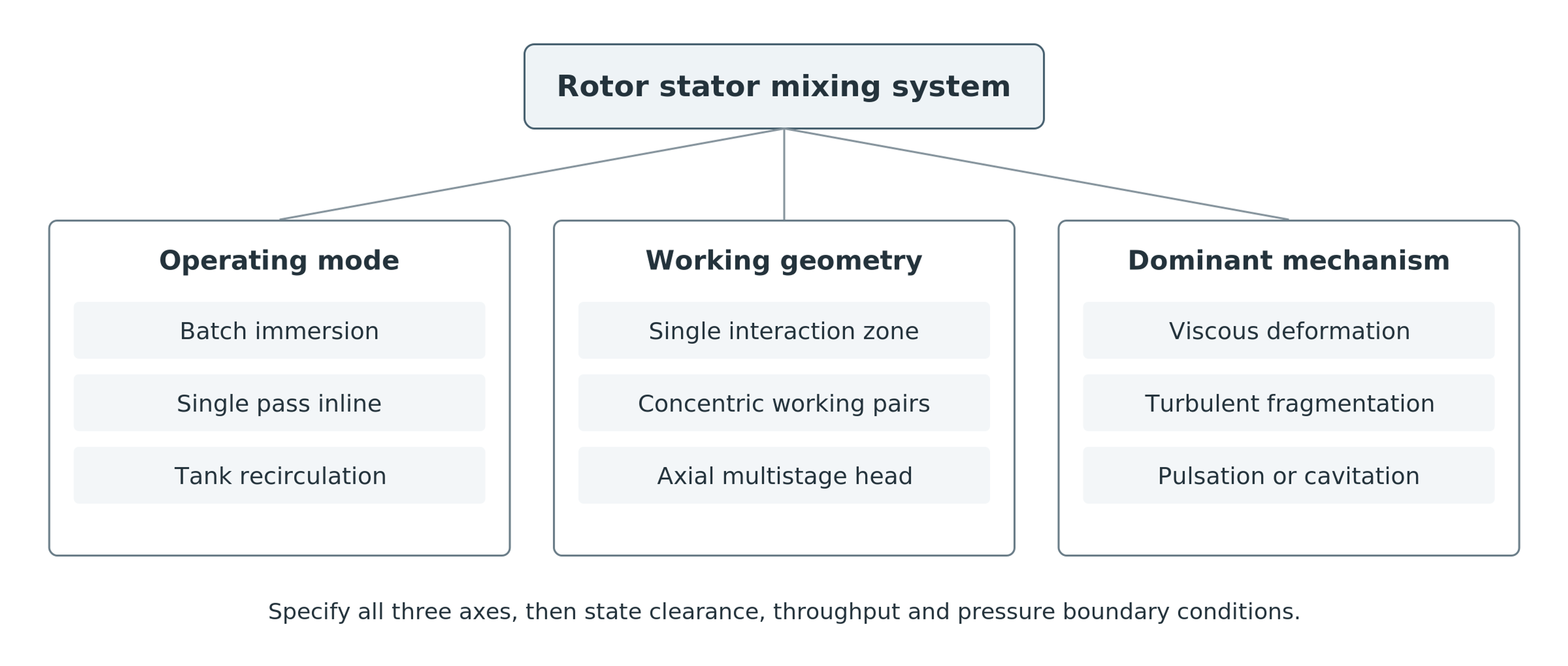
Figure 1.1. Functional classification of rotor-stator systems by operating mode, working geometry, and dominant mechanism. Original explanatory diagram based on source material [1].
2. Principal Components and Kinematics
A batch installation generally comprises a drive, shaft, supports or bearings, immersed mixing head, and vessel. Adequate immersion depth is needed to prevent continuous gas entrainment, while appropriate clearance from the tank floor and walls is needed to establish circulation. A head that produces intense local deformation does not necessarily mix the entire tank effectively. Additional propellers, anchor agitators, or wall scrapers may be needed in large vessels, at increasing viscosity, or when ingredients are introduced nonuniformly [9, 10, 11].
In an inline installation, the working assembly is enclosed in a sealed housing connected to a controlled inlet and outlet circuit. The rotor may develop hydraulic head, but this does not make the mixer a positive displacement pump. Depending on its geometry, imposed flow rate, and downstream resistance, the measured pressure difference may represent either a pressure rise or a pressure loss. Experimental analysis must distinguish energy dissipated within the liquid from useful hydraulic power and mechanical losses [2, 3].
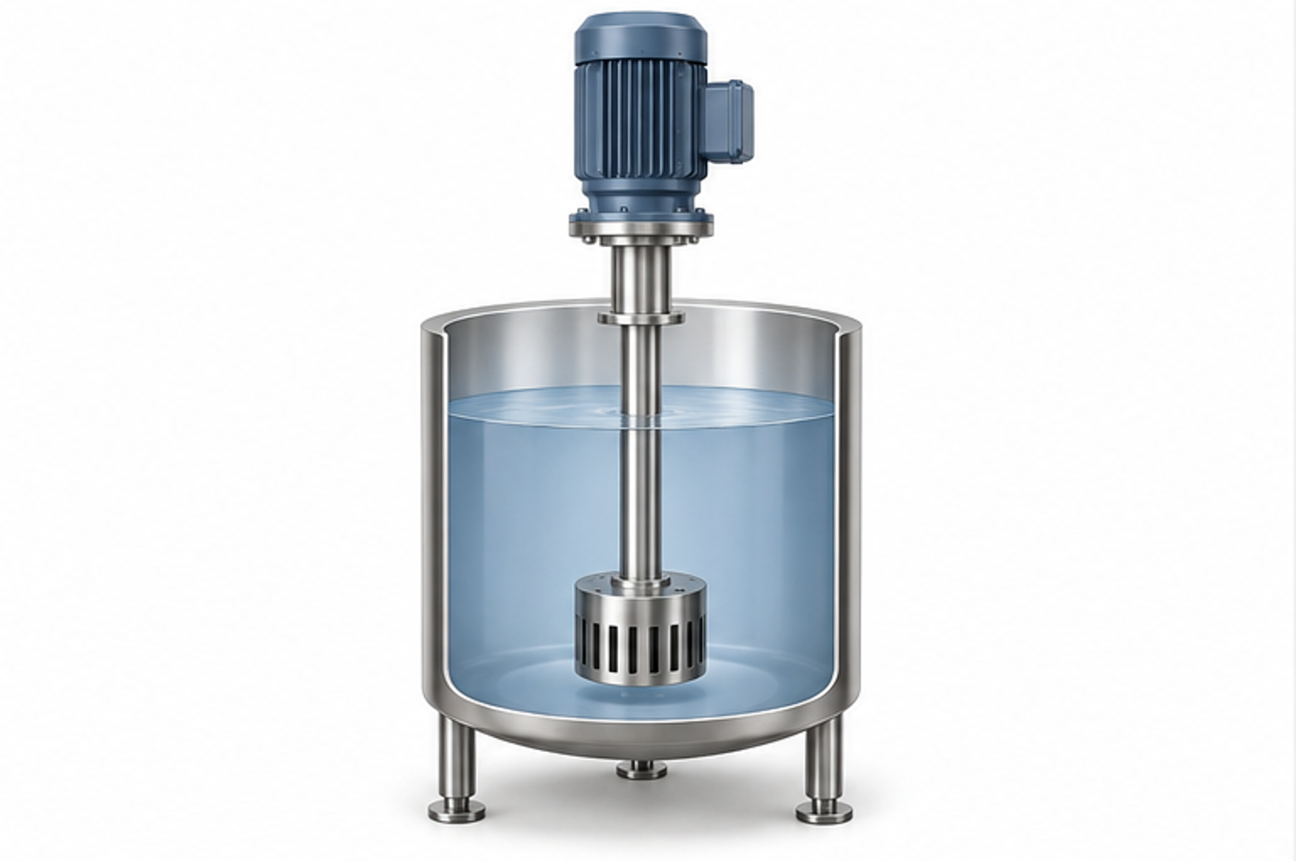
Figure 2.1. Immersed mixing head in a batch vessel. Simplified original illustration of the general arrangement. [1].
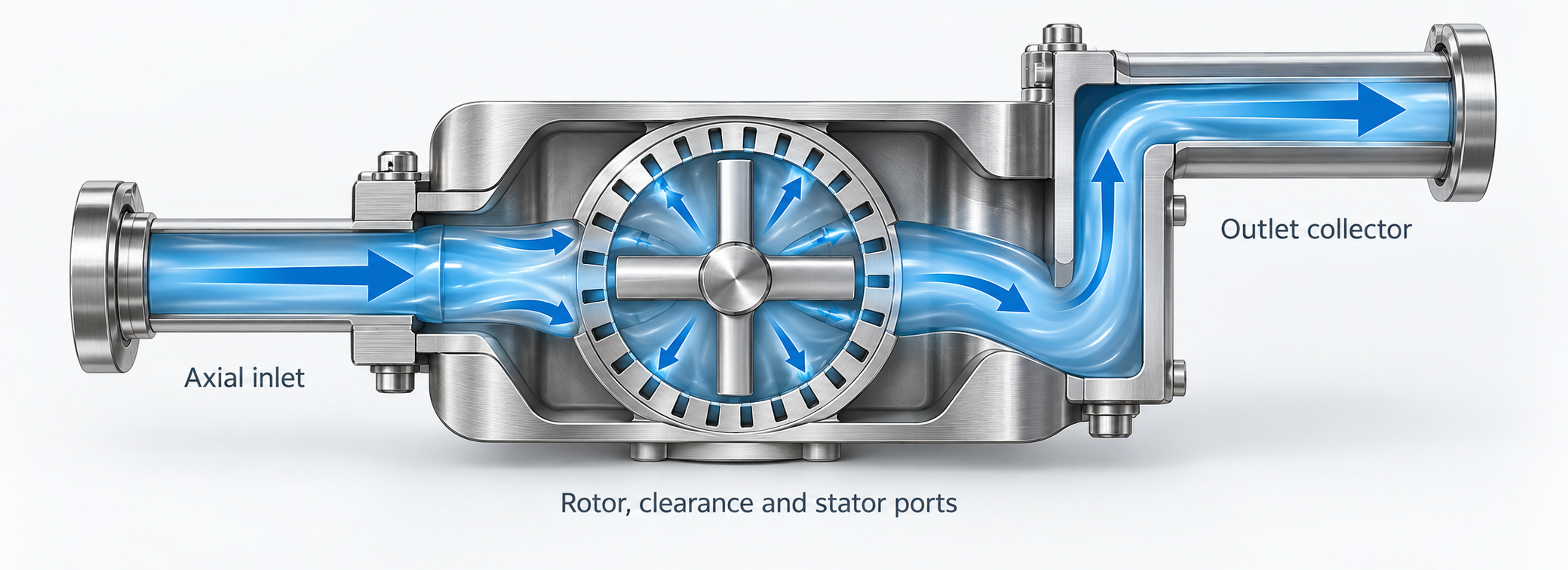
Figure 2.2. Flow path through an enclosed rotor-stator mixer: axial entry, transport across a radial working region, and discharge collection. Original explanatory diagram [1].
2.1 Rotational Speed and Geometric Characteristics
The performance of a rotor-stator mixer depends on the combined effects of operating conditions, particularly rotational speed, and the principal geometric parameters of the working pair. Changing any of these variables changes the overall hydrodynamic flow structure.
Rotational frequency N is expressed in revolutions per second, whereas n is expressed in revolutions per minute. Angular velocity is defined by
where ω is angular velocity in rad/s and N is rotational frequency in s⁻¹.
The outside diameter D of the rotor determines its circumferential or tip speed, given by
where Uₜ is rotor tip speed, D is rotor diameter, N is rotational frequency in revolutions per second, and n is rotational speed in revolutions per minute.
Tip speed is more useful than rotational speed alone when comparing rotors of different diameters. Nevertheless, it is only a kinematic measure: equal tip speeds do not imply equal gap shear rates, aperture velocities, pumping performance, or energy dissipation. Actual working geometry must therefore be considered. The permissible speed for a particular machine must be obtained from the manufacturer; the kinematic curves presented here do not define a safe operating envelope [2, 3].
When z identical, uniformly spaced rotor elements pass a fixed point, their fundamental passage frequency is
where fₚ is the element passage frequency; z is the number of repeating rotor blades, teeth, holes, or cavities; N is revolutions per second; and n is revolutions per minute.
Equation (2.3) gives the fundamental passage frequency at a fixed location, not the full interaction spectrum for rotors and stators with different numbers of elements. Additional spectral components arise from relative spatial phase, nonuniform pitch, shaft speed modulation, and channel geometry. The pressure fluctuation spectrum should therefore be measured when designing equipment for pulsating action.
3. Principal Configurations: Batch and Inline Mixers
3.1 Immersion Batch Mixers
At any instant, an immersed head processes only the material passing through its active region. Batch mixing therefore requires both sufficient local deformation and bulk circulation that continually delivers the remaining liquid to the head. This combination is especially important during polymer hydration, powder addition, and preparation of concentrated suspensions, since changing rheological properties affect both the flow field and the supply of material to the head.
In a small vessel containing a mobile fluid, radial discharge may establish toroidal circulation. In a tall or wide vessel, or in a material having a yield stress, the local circulation loop may communicate poorly with distant regions. Baffles primarily suppress overall liquid rotation but do not, by themselves, guarantee axial exchange. Auxiliary propellers, side-entry agitators, anchors, or scrapers can be selected to feed material to the head and improve heat transfer to the tank wall [9, 10, 11].
Batch processing permits staged ingredient addition, formulation adjustments, and control of treatment duration. Its principal limitations are unequal numbers of passes through the head, sensitivity to the fill level, and possible surface air entrainment. A macroscopically uniform product can still contain elements that have experienced very different levels of intense treatment. This distinction is important for products sensitive to both insufficient and excessive processing.
3.2 Inline and Pipeline Mixers
In inline operation, the mixing head is installed within a closed hydraulic circuit. All discharged material passes through the housing, but internal recirculation, leakage, and nonuniform velocity profiles produce a distribution of residence times. Inline arrangements are well suited to controlled ingredient ratios, continuous production, sealed processing, and integration with premixing equipment or downstream cooling.
The required flow can be produced by the mixer itself, an external pump, or their combined action. Single pass processing must achieve the specified transformation in one traversal. Under recirculation, material undergoes repeated processing while exchanging with the contents of a holding tank. Consequently, a recirculation circuit is not equivalent to a single pass device with a longer residence time. Product quality also depends on tank mixing and the distribution of repeated passes [2, 3].
Inline equipment can be connected to metering manifolds, heat exchangers, powder induction units, degassing systems, and pressure controls. These advantages are accompanied by requirements for mechanical seals, housing strength, inlet feed conditions, and reproducible flow measurements. A published review of the transition from batch to continuous rotor-stator operation shows that use of an identical head does not guarantee identical performance, power distribution, or product quality [12].
3.3 Single-Pass Processing, Recirculation, and Batch Operation
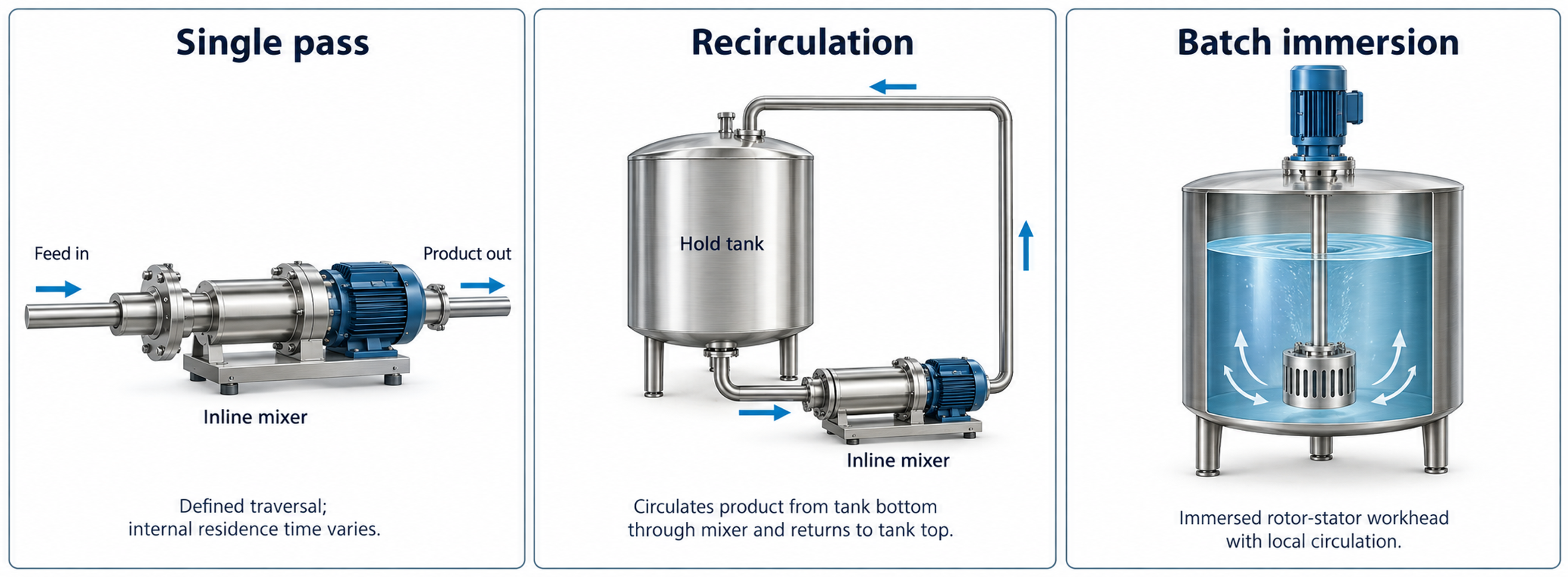
Figure 3.1. Single-pass, recirculating, and immersed batch arrangements. [1].
For an active volume Vₐ and volumetric flow rate Q, the nominal residence time is
where tₐ is the nominal residence time in the active zone and Q is the volumetric flow rate.
For a recirculating tank of volume Vₜ, the mean equivalent number of passes over a processing time t is estimated as
where nₚ is the mean equivalent number of passes, Q is recirculation flow rate, t is processing time, and Vₜ is tank volume.
Interpretation of the Number of Passes
Equation (3.2) defines an engineering average. It assumes ideal tank mixing and does not imply that every fluid element completes exactly nₚ passes. Real installations exhibit residence time distributions, bypass flows, and repeated short circulation loops. Sampling must therefore demonstrate that stable product quality has been achieved.
The mean pass count must not be interpreted as a guaranteed minimum. In an additional idealized model in which a perfectly mixed tank feeds a constant flow circuit and individual passages are statistically independent, approximately 36.8% of the material remains unprocessed after one mean pass, while about 0.67% remains unprocessed after five mean passes. These are ideal probabilities, not measured properties of an actual mixer. Bypass flow and poorly exchanged regions can substantially increase the underprocessed fraction.
The final product should therefore be assessed using samples representative of the entire vessel, rather than solely the recirculation outlet. Time, flow rate, and mean pass count remain useful metrics, but must be interpreted alongside particle or droplet size distributions, rheology, or formulation-specific dissolution criteria.
Table 3.1. Comparison of batch and inline operation
| Criterion | Immersion batch mode | Inline mode |
|---|---|---|
| Material exposure | Statistical; determined by tank circulation and processing time. | All discharged material traverses the housing, but local residence time has a distribution. |
| Suitable duties | Flexible formulation, variable batch size, staged addition, and direct powder loading. | Continuous manufacturing, metered feed, single-pass treatment, and sealed processing. |
| Pumping requirements | The head must supply local suction and bulk exchange; auxiliary agitation may be required. | The rotor may pump liquid, but an external pump is often required to control flow or backpressure. |
| Heat removal | Jacketed vessel, internal coil, or external recirculation loop. | Direct integration of heat exchangers upstream or downstream of the mixer. |
| Scale up considerations | Turnover time, head position, vessel geometry, local intensity, and accumulated energy dose. | Tip speed, stage geometry, residence time in the active zone, capacity, pressure, and energy per unit volume. |
| Main risks | Air entrainment, stagnant regions, unequal exposure, and poor powder induction. | Seal loading, excessive pressure loss, blockage, heating, and insufficient treatment per pass. |
4. Single-Element Systems and Combined Tank Installations
4.1 High Throughput Batch Mixing Heads
High throughput batch heads are designed to combine localized dispersive action with vigorous bulk circulation rather than to maximize throttling through a fine screen. Scott Turbon high-shear batch mixers illustrate this design philosophy: their heads draw material from both above and below the assembly and redistribute it throughout the process vessel.
Such mixing heads operate through three successive functional steps:
Step 1. The rapidly rotating head draws in material from above and below. Specially profiled discharge passages create intensified turbulence and local pressure reduction, allowing high velocity discharge through the nozzles.
Step 2. As the material traverses the nozzles, it experiences intense turbulent motion and shear deformation, then returns to the vessel with substantial kinetic energy, promoting rapid mixing [11].
Step 3. Continued entrainment of fresh material from the upper and lower regions establishes powerful circulation within the vessel and sustains homogenization throughout the process [11].
Scott Turbon classifies its interchangeable shear elements into three principal types: the cage shear element (Type A), toothed disk (Type B), and smooth disk (Type C). These options suit different operating duties:
Type A (cage shear element): Designed for efficient emulsification and incorporation of powdered ingredients.
Type B (toothed disk): Intended for processing high-viscosity formulations.
Type C (smooth disk): Provides greater fluid throughput with reduced shear intensity [13].
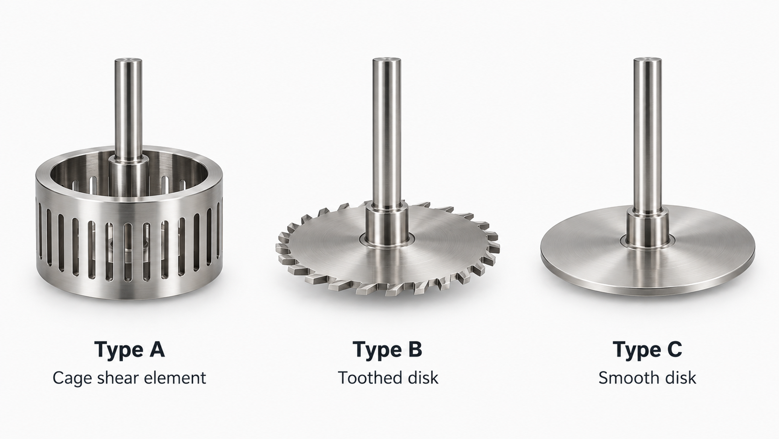
Figure 4.1. Simplified representations of Scott Turbon Type A, B, and C shear elements: cage shear element, toothed disk, and smooth disk [13].
High throughput heads should be distinguished from conventional assemblies in which a rotor operates inside a fixed perforated stator. Equipment should be classified on the basis of the actual interacting moving and stationary surfaces, rather than generalized commercial labels for high-shear devices.
When operating high-throughput batch mixers, maintaining ingredient incorporation as viscosity and other rheological properties change is essential. Design documentation should specify immersion depth, vessel geometry, ingredient addition points, and any auxiliary agitators. Such systems should be compared with enclosed rotor-stator heads on the basis of equivalent final product quality and measured energy use, not simply nominal rotational speed in rpm.
4.2 Enclosed Rotor-Stator Mixing Heads
In an enclosed mixing head, a bladed or toothed rotor rotates within a stationary perforated stator. Axially entering liquid is accelerated by the rotor and discharged through stator openings, producing high local velocity gradients and rapid jets. Interchangeable perforated screens allow a common drive to be adapted for size reduction, dispersion, or emulsification. Silverson, for example, distinguishes general purpose heads, slotted heads, and screens with square or fine emulsifying perforations, illustrating the direct influence of stator geometry on equipment function [10].
Flow restriction by a perforated screen substantially affects pressure distribution and throughput within the mixing head. Higher mean hydrodynamic pressure can coexist with localized low pressure regions around individual openings or behind rotor blades. Reliable assessment of cavitation therefore requires detailed consideration of local pressure, fluid temperature, and flow geometry. A fine screen or high nominal rotor speed alone is not sufficient evidence that cavitation occurs.
Silverson's axial flow design illustrates the relationship between screen geometry and discharge direction: its upward flow differs fundamentally from the radial jets produced by conventional perforated heads [10]. Thus, even substituting a different perforated screen may substantially alter both local hydrodynamic loading and the bulk circulation pattern in the vessel.
4.3 Mixers with Shear-Pumping Capability
A shear pump combines dispersive action with a rotor capable of producing useful flow. Silverson's inline mixers for high viscosity products, for example, employ a dedicated pumping rotor and interchangeable workheads; versions with tangential or vertical discharge connections are also available [14]. These designs demonstrate how pumping and processing functions can be combined while remaining functionally distinct. Actual capacity depends on fluid rheology, inlet conditions, and the hydraulic circuit.
A shear pump has a head versus flow characteristic rather than a fixed delivery rate. Changes in downstream resistance alter throughput, internal recirculation, and power distribution. For viscous or shear thinning products, motor selection must account for torque throughout the process, including startup and ingredient addition. A manufacturer's quoted water flow rate does not guarantee the same performance with a particular product.
4.4 Combining Rotor-Stator Mixers with Conventional Agitators
Conventional mixing devices can complement the localized action of a rotor-stator head. Propeller agitators promote axial transport, anchor agitators renew fluid near the wall, and scrapers improve heat transfer in highly viscous materials. A high-shear head can also be installed near the base of a sealed or vacuum vessel, while a slower agitator maintains overall circulation. Such equipment combinations should be analyzed as integrated mixing systems rather than as unrelated individual machines.
Auxiliary circulation should direct untreated material into the active region while avoiding both aeration and short-circuiting of material that has already been processed. Poor bulk exchange can create local overheating alongside stagnant, untreated regions. Conversely, excessive or poorly directed circulation can destabilize the inlet flow. An appropriate hydrodynamic balance is obtained by comparing the vessel turnover time, local residence time within the shear region, and the product's sensitivity to repeated mechanical and thermal exposure.
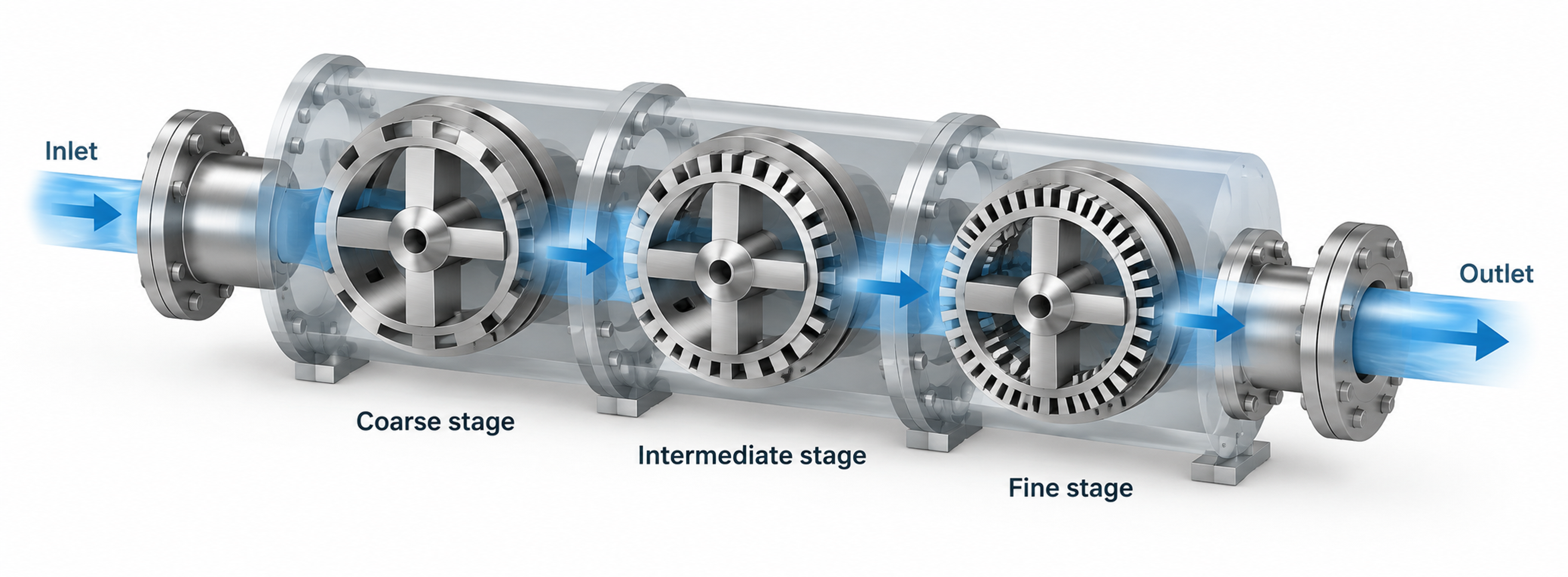
Figure 4.2. Consecutive coarse, intermediate, and fine processing zones in a conceptual inline layout. [15, 16].
Table 4.1. Single element systems and their primary functions
| Arrangement | Principal advantage | Characteristic limitation |
|---|---|---|
| Open, hig -throughput batch head | Fast powder induction, good tank circulation, and tolerance of larger particles. | Local stress and flow rate require verification for the chosen geometry. |
| Enclosed batch head | Interchangeable stators, intense local shear, and radial jets. | Large or viscous batches may require auxiliary agitation. |
| Single stage inline rotor-stator mixer | Defined flow path and compact incorporation into a process line. | Single-pass effectiveness depends on inlet distribution and flow rate. |
| Shear pump | Higher throughput and solids-handling capacity when rotor or ring geometry is chosen appropriately. | Without a finer downstream stage, the target minimum droplet or agglomerate size may not be achieved. |
| Rotor-stator head with slow agitator | Combines intense local treatment with bulk exchange and heat transfer to tank walls. | More complex mechanics and possible interactions between the flow fields. |
4.5 Comparative Analysis of Leading Manufacturers' Designs
Table 4.2. Comparison of design features and their engineering implications for equipment from leading manufacturers
| Manufacturer and series | Documented design feature | Engineering interpretation |
|---|---|---|
| Scott Turbon (batch mixing heads) | Dual sided vertical intake; interchangeable Type A, B, and C shear elements [11, 13]. | Bulk circulation, phase wetting, and local processing intensity must be assessed together. |
| Kinematica (MEGATRON® MT-V series) | One stage or three stage dispersion chambers with configurable generators, cooling jackets, and seal options [16]. | The active zone, temperature control, and seals form an integrated functional system. |
| Silverson (standard heads and HV series) | Interchangeable perforated screens and a dedicated pumping rotor in the HV series [10, 14]. | Screen-controlled shear deformation must be distinguished from hydraulic pumping capacity and pressure head. |
| IKA (DISPAX-REACTOR® DR series) | Three successive inline rotor-stator generator stages [15]. | Progressive dispersion gradients and control of flow rate and specific energy input per pass. |
5. Single Stage and Multistage Mixers
A single stage mixer has one localized zone of hydromechanical interaction between rotor and stator. Multiple perforations in one stator screen do not constitute multiple processing stages. The relatively simple design reduces holdup volume, facilitates inspection, maintenance, and cleaning, and often provides adequate intensity for wetting, mixing, and moderate dispersion. Actual hydraulic pressure losses and shear stress distributions are nevertheless determined by the geometry of the working elements.
In a multistage mixer, hydromechanical treatment zones are positioned sequentially along the process flow. This allows progressive processing: an initial coarse stage precedes more restrictive stages, reducing the mechanical load imposed by large agglomerates on the final generator. Stages may be arranged along the machine axis or as concentric cylindrical elements. The term stage must therefore be interpreted within the architecture of the specific machine. IKA describes its DISPAX-REACTOR® DR 2000 as a three stage inline disperser, whereas the rotor-pulsation literature describes both concentric and disk-type assemblies [2, 5, 6, 7, 15].
Adding stages exposes the material to more deformation events but also increases hydraulic resistance, holdup volume, localized heat generation, abrasive wear, and the complexity of cleaning and sterilization in place (CIP/SIP). Stages mounted on one shaft have the same angular velocity but different tip speeds if their active radii differ. Similarly, a restrictive fine dispersion stage does not necessarily dissipate the same fraction of input power as the initial stage. Stage count is therefore an important design variable, but not a universal measure of overall hydromechanical processing efficiency.
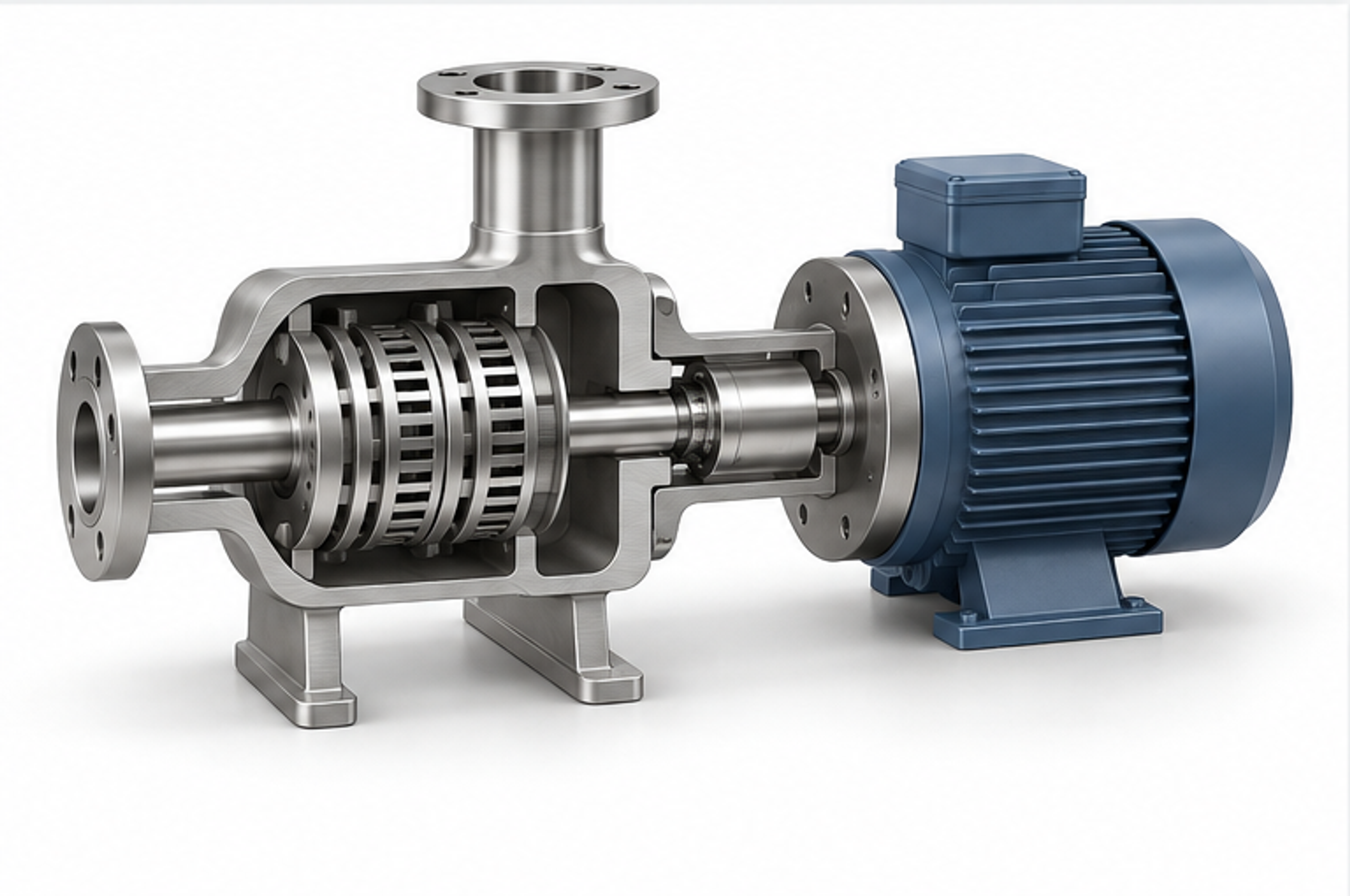
Figure 5.1. Simplified illustrative reconstruction of a multistage rotor-pulsation apparatus with an enclosed processing chamber. RU 55302 U1. [7].
Table 5.1. Comparison of single-stage and multistage designs
| Characteristic | One stage | Multiple stages |
|---|---|---|
| Hydraulic resistance | Often lower for comparable geometries; not a universal law for pumping systems. | Usually increases with added active zones or narrower passages. |
| Particle tolerance | Generally more tolerant of large or fibrous ingredients. | Progressive narrowing or pretreatment may be required to avoid blockage. |
| Energy distribution | One principal active region. | Energy is distributed among stages, sometimes at increasing intensity along the radius or axis. |
| Product quality control | Simpler construction and characterization. | More options for staging and interchangeable generator combinations. |
| Heat generation | Depends on dissipated power relative to throughput. | May be substantial because the same liquid encounters repeated treatment within one pass. |
| Maintenance | Fewer components and interfaces. | More demanding disassembly, alignment, and clearance control. |
| Primary duties | Mixing, wetting, moderate dispersion, and high flow rate. | Fine emulsification, deagglomeration, and intensive single-pass processing. |
5.1 Process Characteristics and Hydrodynamic Validation of Multistage and Modular Inline Systems
Multistage and modular inline systems can optimize dispersion by distributing deformation across consecutive processing zones. The IKA DISPAX-REACTOR® DR 2000 provides an example, with three sequential rotor-stator pairs and interchangeable generators intended to produce fine emulsions and relatively narrow particle size distributions in a single pass [15]. The principal advantage is progressive size reduction: upstream stages accept the loading from coarse agglomerates and help protect the narrow clearances of downstream precision generators against blockage and wear. Modular units such as the Kinematica MEGATRON® MT-V combine one-stage or three stage rotor-stator chambers with temperature control jackets and specialized mechanical seals, forcing flow through a selected geometry [16]. However, capacities stated for Newtonian reference liquids, particularly water, are only baseline indications of hydraulic potential. They cannot be extrapolated to process products without accounting for rheology, solids concentration, and seal limitations. Modularity facilitates the transition from laboratory to production scale, but hydrodynamic and energetic similarity still requires experimental verification.
Accurate evaluation of individual stages requires measurements of hydrodynamic and thermal conditions. Where suitable instrumentation ports exist, local pressure differences and temperature gradients should be measured across individual generators and across the complete machine. Adding a restrictive final fine dispersion stage may increase hydraulic resistance, reduce throughput, increase mean residence time in the shear zone, and raise thermal loading. Improved dispersion cannot automatically be attributed only to increased local shear stress (). The contributions of geometry, single pass residence time, and accumulated energy input should be distinguished experimentally.
6. Types of Stators
The stator determines hydraulic resistance, edge interactions, and the character of the discharge flow. Its main parameters are open area, hole or slot dimensions, wall thickness, edge profile, clearance, and the spatial arrangement of openings. General purpose heads commonly use interchangeable screens. Rotor-pulsation apparatuses may use toothed rings, opposing disks, or stationary crowns that interact periodically with rotor channels [4, 5, 6, 7].
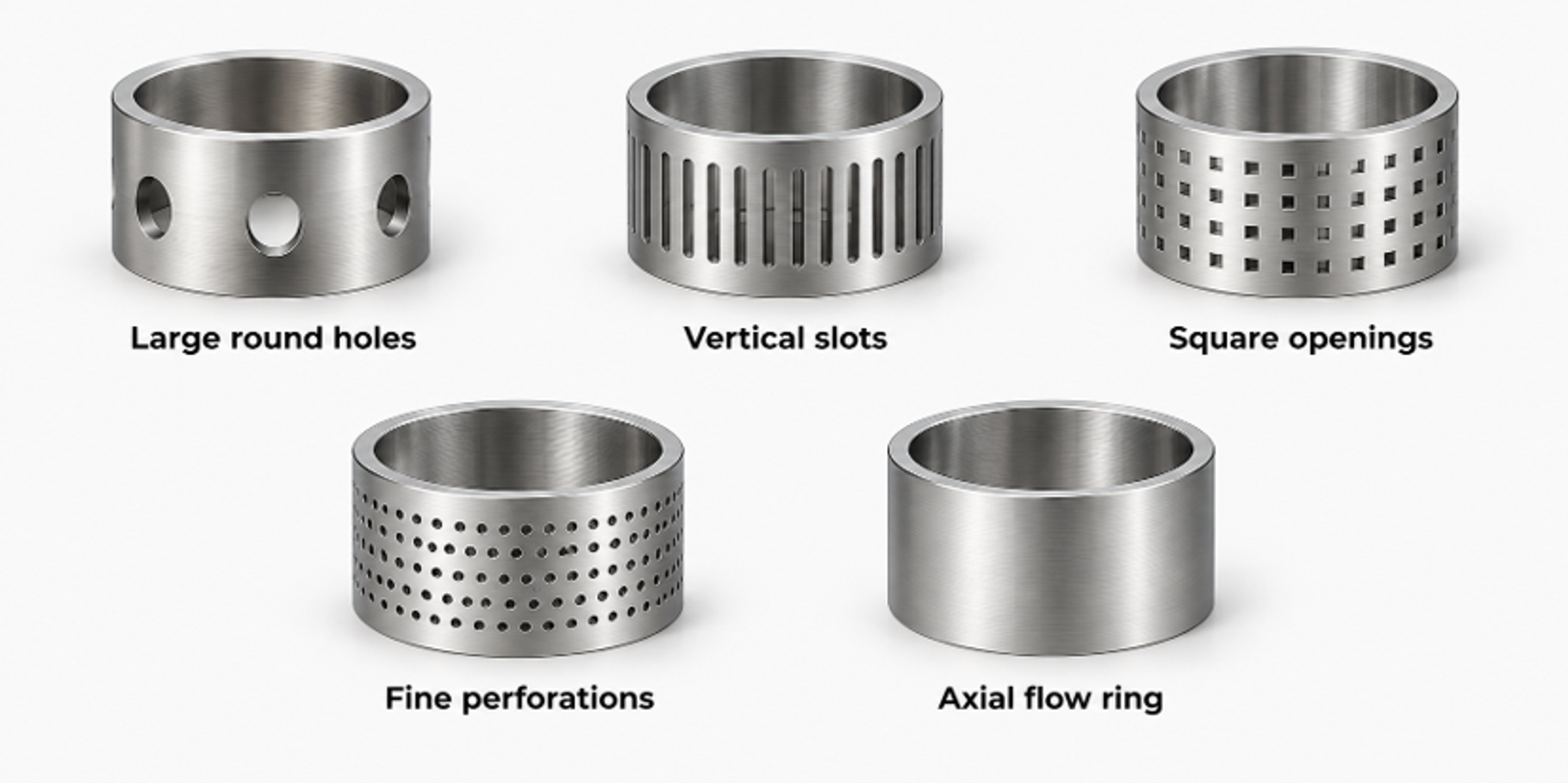
Figure 6.1. Functional screen geometries: large round holes, vertical slots, square openings, fine perforations, and an axial-flow ring [10].
Table 6.1. Functional characteristics of principal stator types
| Stator type | Hydraulic action | Typical application | Design limitation |
|---|---|---|---|
| Large round holes | Large open area, intense radial jets, and relatively low pressure loss. | General mixing, dissolution, and large soft solids. | Limited deformation at fine scales without a small gap or high tip speed. |
| Vertical or diagonal slots | Long shearing edges and directional jets. | Fibrous materials, deformable solids, gels, and rapid breakup. | Stress concentration and wear can occur at slot ends. |
| Square-hole screen | High edge density and greater flow restriction than large round holes. | Pigment dispersion, colloidal suspensions, and fine solids. | Prone to blockage by large soft lumps. |
| Finely perforated emulsifying screen | Many small jets and high local deformation. | Liquid emulsification and fine dispersion. | High pressure loss, heating, and demanding cleaning requirements. |
| Toothed stator ring | Periodic alignment with rotor teeth and pronounced pressure modulation. | Rotor-pulsation treatment, homogenization, and mass transfer. | Frequency and amplitude depend on tooth number and relative phase. |
| Pin stator | Separated wakes, local vortices, and potential cavitation behind obstacles. | Rotational cavitation and reaction processing. | Severe erosion and fatigue are possible under cavitating conditions. |
| Conical stator | Variable clearance and progressive acceleration. | Viscous materials and controlled pressure recovery. | Axial position and thermal expansion change the clearance. |
| Opposing stator disks | Short axial passages and repeated disk interactions. | Multistage rotor-pulsation assemblies. | Precise alignment and dependable control of axial forces are required. |
Hole count alone does not adequately characterize a stator. The same total open area can be achieved using a few large holes or many small holes, but the total edge length, jet size, wall thickness, and interactions with rotor position will differ. Cleanability and the risk of blockage by fibers should be assessed using the same geometry that forms the basis of hydrodynamic analysis.
7. Rotor Geometry and Its Effects on Hydrodynamics and Process Energy
Rotor geometry governs angular momentum transfer, the head versus flow characteristic, local relative velocity profiles, and the frequency of hydrodynamic interaction with the stator. Different working element configurations provide different mechanisms of hydromechanical action:
-
Straight blades primarily generate radial flow with developed turbulent wakes that promote bulk mixing.
-
Wedge shaped blades produce converging and diverging flow regions with pronounced shear and axial extension, helping to break up structures in emulsions and suspensions.
-
Toothed crowns or rings intermittently obstruct flow passages at high frequency, producing pressure and flow pulsations.
-
Pin elements generate strong separated flows and vortex structures.
-
Concentric ring assemblies enable multilevel processing at several active radii with progressively increasing circumferential speeds.
Modern dispersers often combine these geometries within a single working assembly. The combined effects of the individual elements must be analyzed separately to interpret power dissipation, energy transfer efficiency, and the final particle size distribution correctly [3, 6, 7, 9].
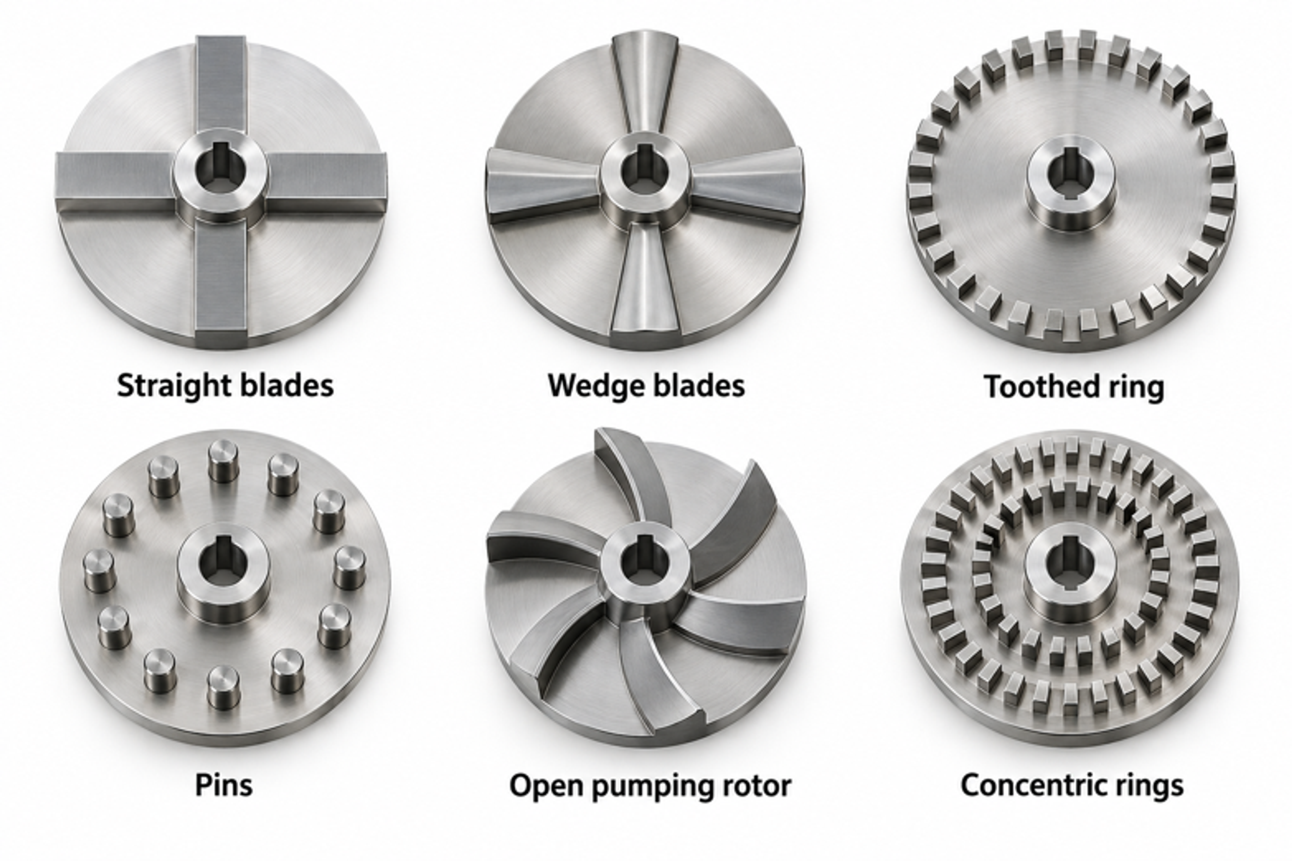
Figure 7.1. Representative rotor types shown schematically in plain view. Differences in blades, teeth, pins, and active radii affect pumping action and interaction with the stator [1].
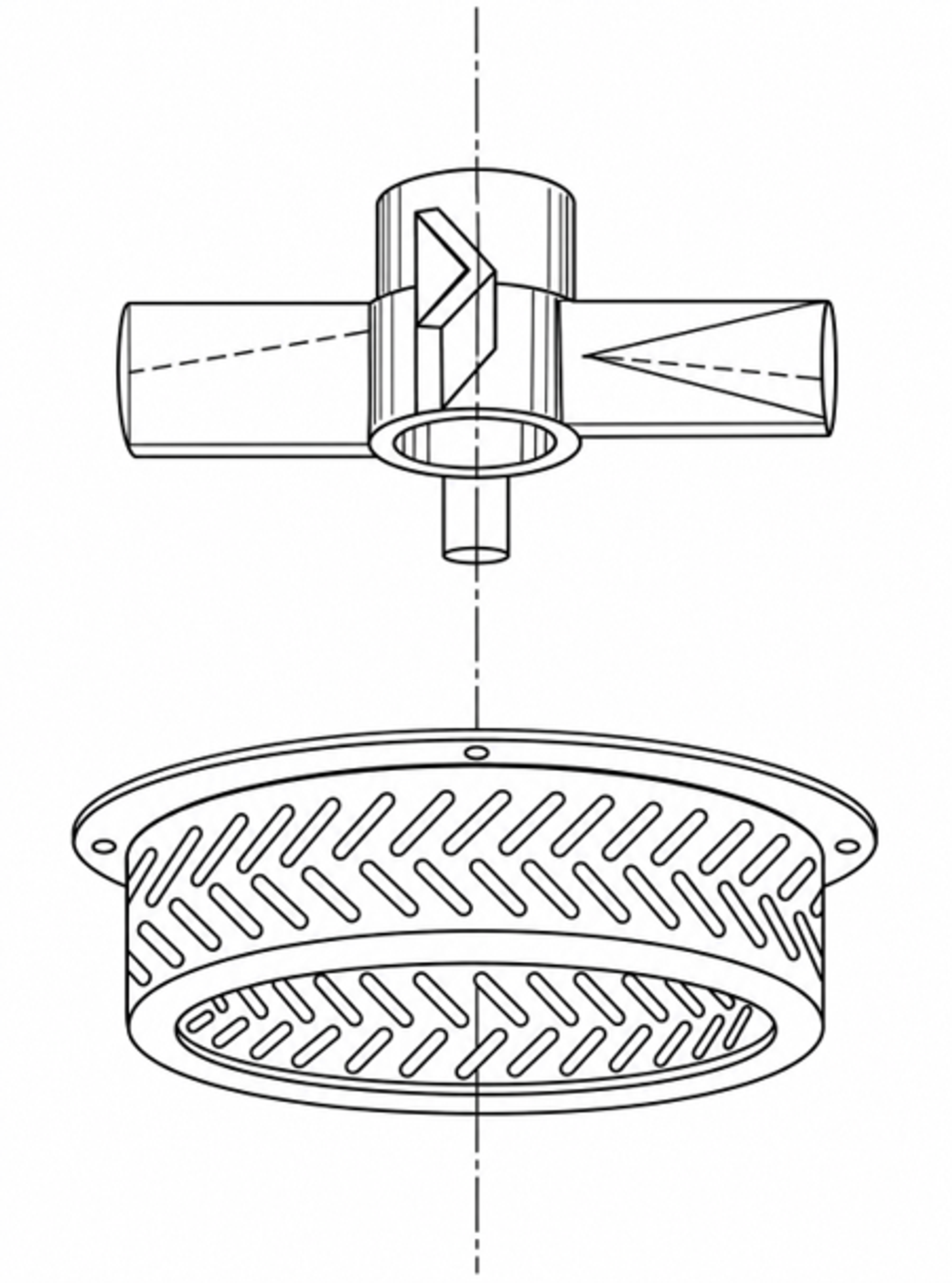
Figure 7.2. Concept of a four-blade wedge rotor with matching inclined stator slots. Redrawn from Figure 3 of U.S. Patent 6,000,840. [9].
Table 7.1. Functional characteristics of principal rotor types
| Rotor type | Principal action | Suitable processes | Important parameters |
|---|---|---|---|
| Straight blade disk | Radial pumping, gap shear, and blade-wake turbulence. | General dispersion and emulsification. | Blade height, number, leading-edge thickness, and clearance. |
| Wedge blade | Convergent deformation and pressure generation. | Fine dispersion, deagglomeration, and emulsification. | Wedge angle, orientation, and stator slot angle. |
| Toothed ring | Periodic channel obstruction and repeated shear at tooth tips. | Rotor-pulsation treatment and high-frequency mixing. | Tooth count, phase, radial overlap, and clearance. |
| Pin rotor | Vortex shedding and high local speeds around pins. | Cavitation, extraction, and reactive mixing. | Pin diameter and pitch, clearance, and cavitation number. |
| Open high throughput rotor | Strong axial entrainment and bulk circulation with distributed shearing edges. | Powder wetting, hydration, and batch processing of viscous products. | Pumping coefficient, free area, and head position. |
| Multiring rotor | Multiple concentric active zones with increasing tip speed. | Multistage single pass treatment. | Diameter of each ring, free flow area between stages, and stage sequence. |
| Cavity or hole rotor | Repeated low-pressure regions inside cavities or holes. | Rotational hydrodynamic cavitation. | Hole diameter and depth, cone angle, number of holes, and pressure recovery. |
Rotor replacement or modernization requires comprehensive verification of structural and hydrodynamic compatibility with adjacent machine components. Checks must include precise shaft mounting, direction of rotation, available drive torque relative to startup and operating loads, and geometric and functional compatibility with the stationary stator.
The conceptual wedge rotor illustration depicts a four-blade configuration interacting with paired inclined stator slots, as described in the patent literature [9]. It is intended only to illustrate the operating principle; overall dimensions, tolerances, and component identifiers have intentionally been omitted. Consequently, it cannot serve as a manufacturing drawing, a basis for direct fabrication, or a reliable source of radial rotor-stator clearance dimensions.
8. Detailed Description of Operating Principles
In rotor-pulsation apparatuses, the principal hydromechanical effect arises from periodic changes in flow cross sectional area as rotor perforations move relative to stator openings. Alignment of the passages permits fluid flow, while partial obstruction produces local throttling, acceleration, or redirection and generates sharp pressure fluctuations upstream and downstream of the overlap region. This principle is used in liquid dispersion equipment, including fertilizer preparation systems described by Voitiuk and Borkhalenko [4]. The pulsations can be accompanied by strong turbulence or cavitation, but their amplitude and the onset of cavitation depend directly on the geometry of the working zone and hydraulic boundary conditions [5, 6, 7].
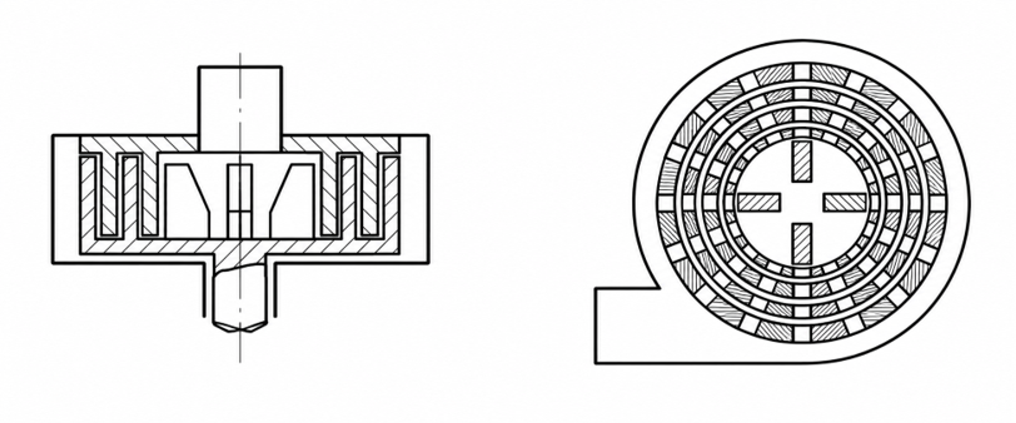
Figure 8.1. Concentric rotor-stator pair shown in sectional and plan views. Simplified illustrative reconstruction based on a rotor-pulsation design [4].
The operation of a conventional batch mixing head can be divided conceptually into four interrelated functions:
-
Intake: Transport of feed material to the rotor inlet.
-
Acceleration and deformation: Transfer of momentum to the moving fluid and initial deformation of the incoming material by the rotating rotor elements.
-
Intensive shear: Passage of fluid through narrow rotor-stator gaps and stator openings, accompanied by steep velocity gradients and extensional deformation.
-
Discharge and circulation: Formation of high velocity discharge jets that entrain surrounding liquid and complete the vessel's bulk circulation loop.
These functions do not constitute distinct thermodynamic stages. They overlap both spatially and temporally within the active fluid volume [9, 10].
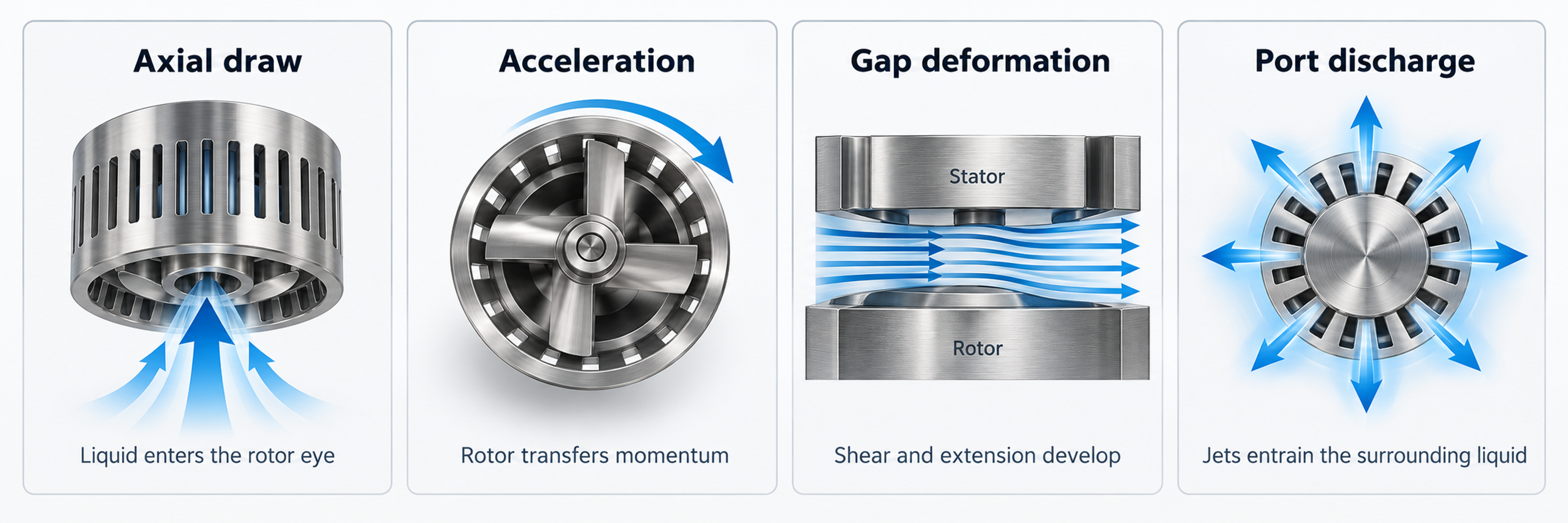
Figure 8.2. Four overlapping functions of a conventional mixing head: intake, acceleration, deformation, and discharge [1].
In inline mixers, an analogous momentum transfer process takes place within sealed housing. Interaction of the rotor with the incoming flow, together with redistribution of velocity, pressure, and turbulence by the stator and outlet manifold, means that outlet pressure can influence the conditions inside the mixing head. Backpressure can, for example, suppress vapor formation and cavitation, but its effect on throughput and energy consumption must be evaluated using the actual system head versus flow characteristic.
Four characteristic time scales are useful when interpreting experimental data: the period of one shaft revolution, the passage time of an individual perforation element, residence time in the active deformation region, and overall circulation or tank turnover time. These quantities often differ by orders of magnitude. Increasing the frequency of rotor-stator interactions does not necessarily increase the rate of tank recirculation, while increasing bulk flow may reduce the specific energy imparted during each pass at a fixed tip speed. Considering all these factors avoids attributing every change in product quality to nominal shear rate alone.
9. Theoretical Basis of Hydromechanical Processes in Rotor-Stator Systems
Theoretical analysis of rotor-stator mixers examines the kinematic and dynamic flow parameters governing dispersion, homogenization, and mass transfer. A key determinant of mechanical action is rotor tip speed , which combines working element geometry, particularly rotor diameter () with drive kinematics, including rotational frequency () and angular velocity ().
The analytical relationship between rotor diameter, rotational speed, and tip speed given in Equation (2.2) provides an estimate of the potential shear deformation and energy transfer to the flow [1].
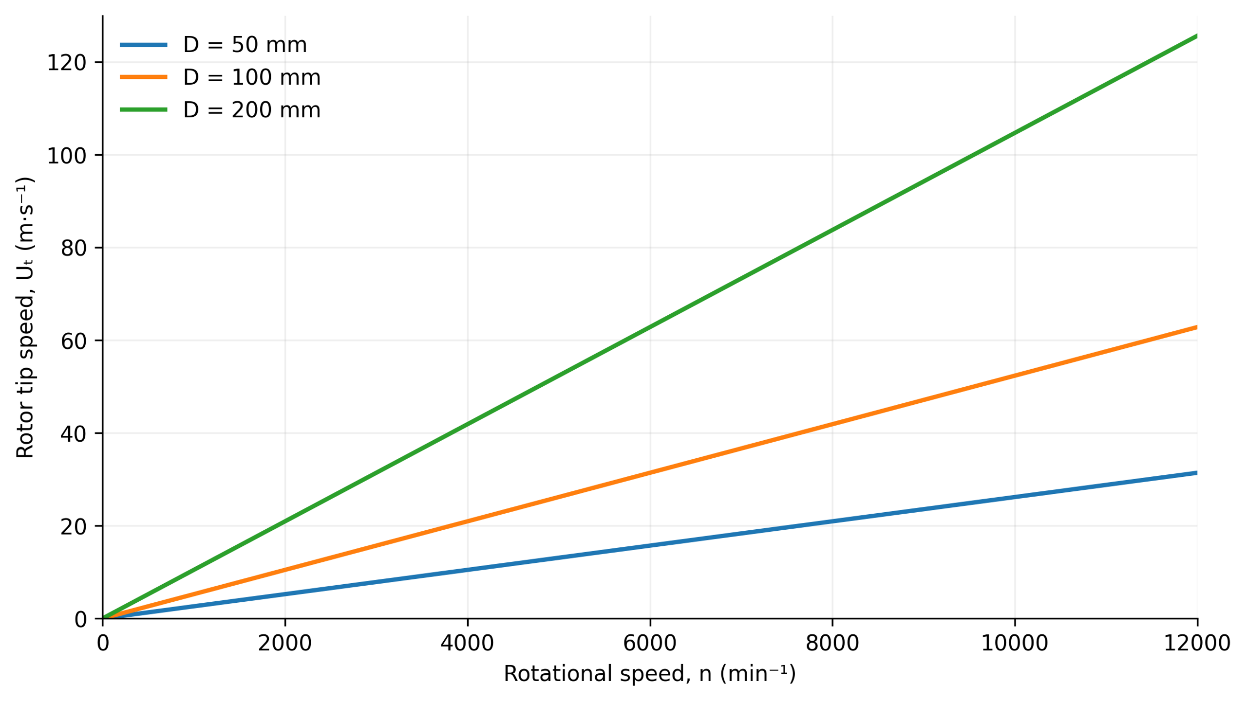
Figure 9.1. Calculated rotor tip speed as a function of diameter and rotational speed according to Equation (2.2) [1].
9.1 Velocity Gradients and Intensive Shear Stresses
In first approximation, the relative fluid velocity changes across an effective gap of width g. The nominal shear rate is
where γ̇ₙₒₘ is the nominal shear rate, Uᵣₑₗ is relative velocity in the gap, and g is the effective gap width.
For a Newtonian continuous phase, viscous shear stress is related to shear rate by
where τ is shear stress and μ is dynamic viscosity.
The estimate based on the gap is useful for comparison but does not fully describe local velocity fields. Leakage, recirculation, blade wakes, and acceleration through stator openings can produce local deformation rates both above and below the nominal estimate. In Rueger's laminar batch experiments, droplet breakup corresponded to simple shear rates roughly twice those estimated from the nominal gap. That factor is specific to the tested configuration and is not a universal correction [2].
For a non-Newtonian formulation, the preceding stress equation represents only the Newtonian limiting case. Predictions additionally require an appropriate constitutive model and, when relevant, allowance for yield stress, thixotropy, or elasticity. Viscosity measured at a single low shear rate cannot be used to represent the entire high-gradient working region.
Fluid accelerating through a converging passage also undergoes extension. A representative axial extensional strain rate is
where ε̇ₓ is the axial extensional strain rate and uₓ is the velocity component in the x direction.
During extension, a fluid element elongates in one direction and contracts in others. This mechanism is important for deformable interfaces and polymeric materials, although the outcome depends on the deformation history and material response. Leading blade edges, wedge surfaces, and entrances to openings generally produce mixed flows rather than the uniform shear of an ideal rheometer.
The ratio of inertial to viscous effects on the rotor scale is defined as
where Reᵣ is the rotor Reynolds number, ρ is density, N is revolutions per second, D is rotor diameter, μ is dynamic viscosity, and ν is kinematic viscosity.
An additional Reynolds number is defined using the clearance and its associated relative velocity:
where the characteristic scales for Re₉ are relative velocity Uᵣₑₗ and gap width g.
The rotor and gap Reynolds numbers describe different scales. A high value at the rotor scale can coexist with relatively ordered flow within a narrow viscous gap. Conversely, separation at an opening may generate fluctuations that a simple gap model does not represent. Neither definition establishes a universal transition threshold for all mixer geometries.
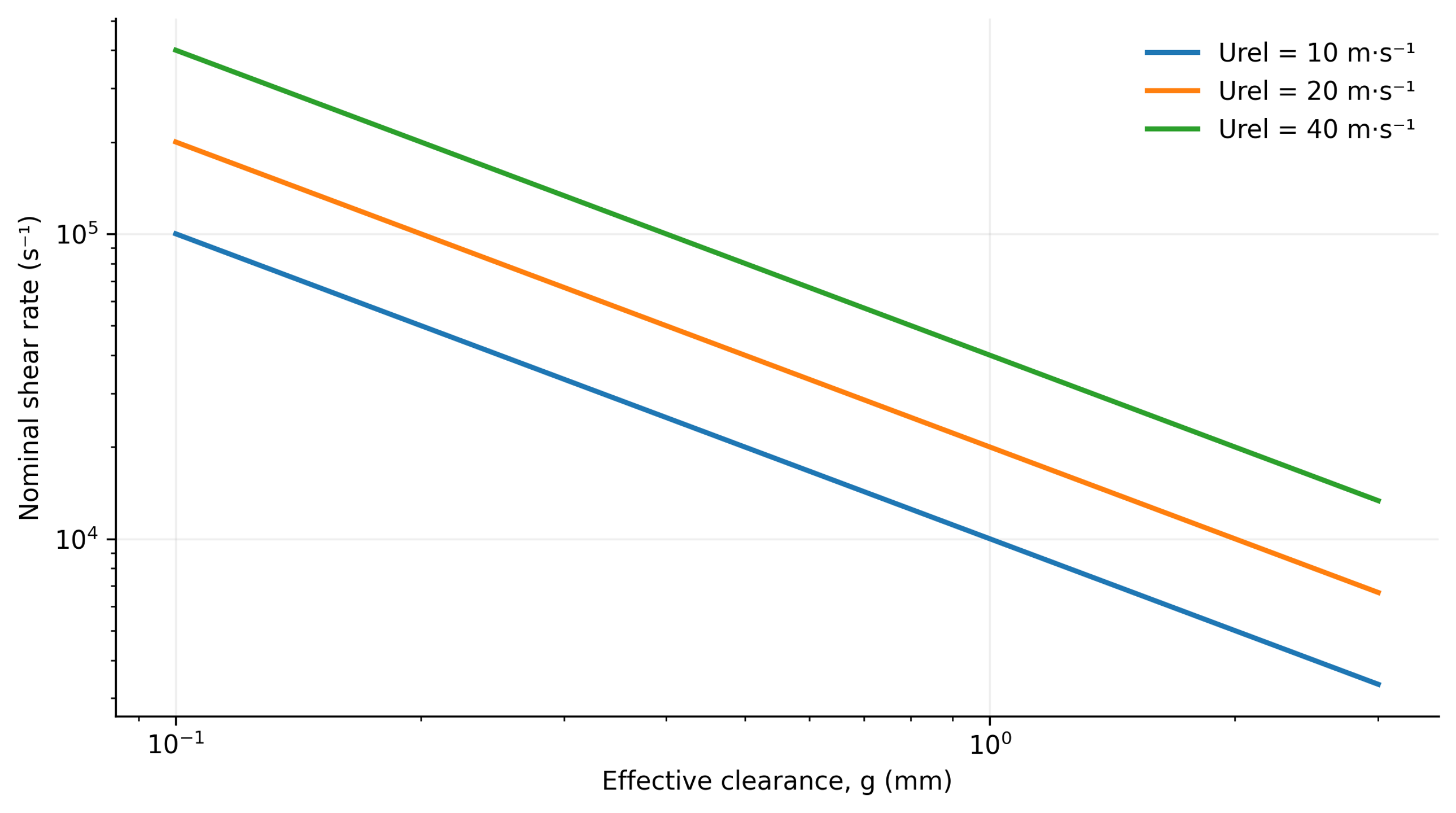
Figure 9.2. Nominal gap shear rate for three relative velocities calculated using Equation (9.1). Effective clearance is a model input and does not account for local gradients near openings or in wakes [1].
9.2 Torque, Power, Pumping, and Energy Dissipation
Torque T and rotational frequency determine the mechanical power transmitted by the shaft:
where Pₛ is shaft power, N is rotational frequency in s⁻¹, and T is torque.
Shaft power is not equal to the power dissipated within the liquid. Mechanical losses and net hydraulic power transferred to the flow must be considered before calculating dissipation. Loss characteristics approved by the manufacturer may be compared with calorimetry and flow and pressure measurements. Mechanical seals must not be operated dry merely to establish a baseline loss measurement. Nearly all dissipated energy ultimately becomes heat, but calorimetric analysis must account for heat transfer and energy crossing the boundaries of the control volume.
The power number is defined using power dissipated in the liquid:
where Po is the power number and is power dissipated in the processed liquid.
Dimensionless throughput and pressure rise are expressed as
where Φ is the flow coefficient and Q is volumetric flow rate.
where Ψ is the pressure coefficient and Δp is the pressure change across the mixer, positive for pressure generation and negative for pressure consumption under the specified sign convention.
For a positive useful pressure rise, the hydraulic power fraction is
where ηₕ is hydraulic efficiency. A low value of ηₕ is not necessarily a disadvantage for a mixer because intentional viscous dissipation is often the primary process objective.
Rueger found that the dissipative power component of an IKA inline mixer was nearly independent of flow rate over part of the tested turbulent range. The measurements were described by a correlation involving effective diameter and stage count [2]. Computational analyses of a Silverson inline head demonstrate the importance of unsteady rotor-stator interactions and turbulence model selection for predicted throughput and power [3]. These findings support calibration for each geometry rather than adoption of a single power number for all high shear mixers.
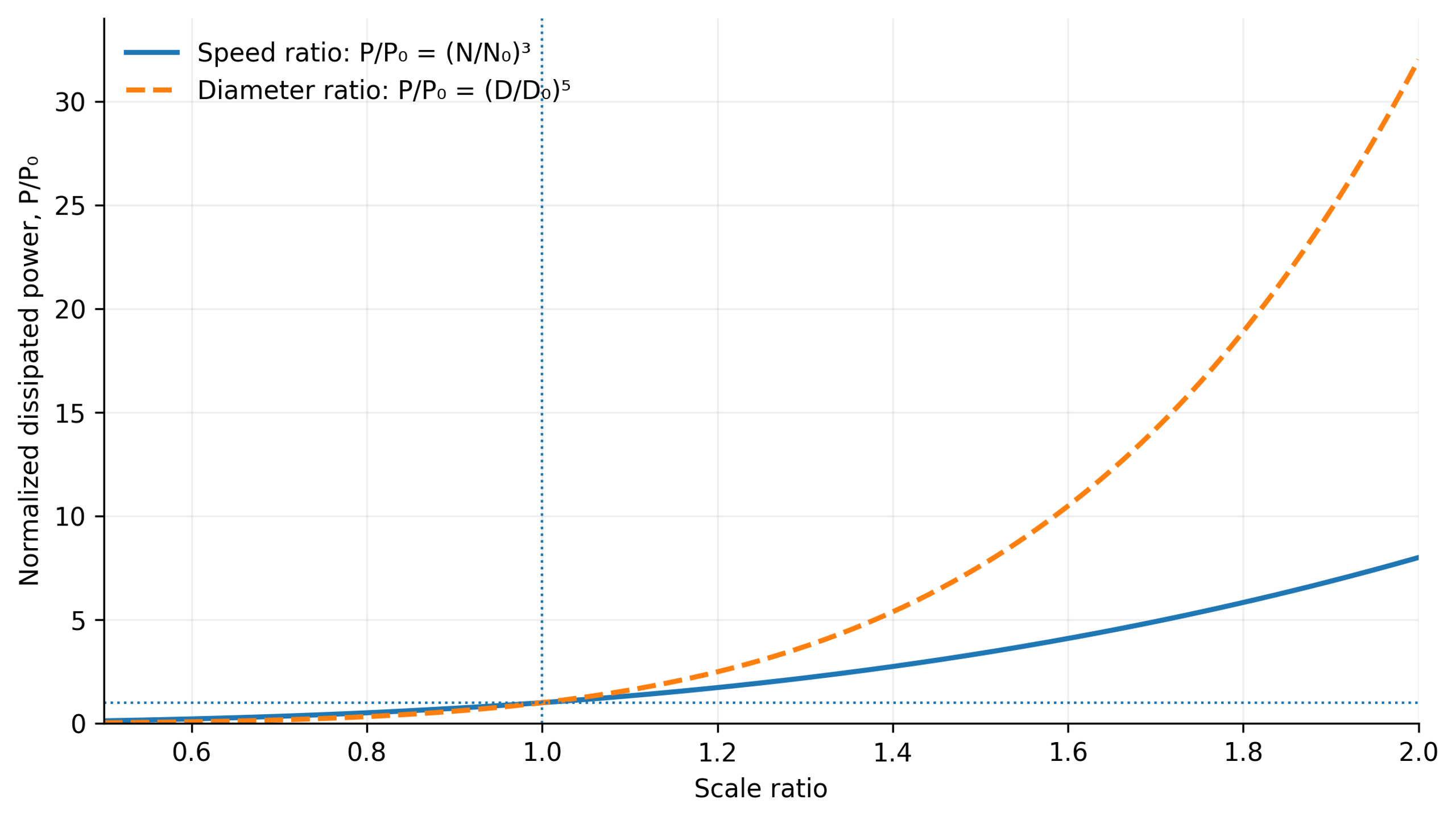
Figure 9.3. Idealized sensitivity of power to rotational speed and rotor diameter based on Equation (9.7), assuming constant density and power number. Only the indicated independent parameter varies on each curve [1].
The definition of the power number must be stated whenever results are compared. Equation (9.7) uses dissipated power, whereas experiments may report measured shaft power. The values agree only if the neglected terms are genuinely small. A negative pressure rise denotes a mode that consumes pressure head; in that case, Equation (9.10) is a signed power ratio rather than the conventional positive efficiency of a pump.
The mean rate of energy dissipation per unit fluid mass in a specified averaging volume V is
where is the mean specific dissipation rate in W/kg; is dissipated power; ρ is density; V is the averaging volume.
For a selected active region, volumetric dissipation is estimated by dividing the power dissipated there by the region volume:
where εᵥ,ₗₒ꜀ is the local volumetric energy dissipation rate in W/m³, Pₗₒ꜀ is the power dissipated in the active region, and Vₐ is its volume.
Dissipation Rate Is Not the Same as Accumulated Energy Density
Energy dissipation rate is expressed as power per unit mass or volume, for example W/kg or W/m³. Accumulated specific energy is expressed in J/kg or J/m³ and incorporates treatment duration or flow rate. These metrics address different questions: local dissipation characterizes instantaneous deformation, while accumulated energy describes the dose delivered per pass or per batch.
In steady inline operation, the dissipated energy per unit volume of processed material is
where Eᵥ,ꜰᴛ is inline specific volumetric energy in J/m³, a quantity dimensionally equivalent to pressure in Pa.
For a batch operated at constant dissipated power over a duration t, the nominal accumulated energy dose is
where Eᵥ,ʙ is the nominal batch specific volumetric energy and Vₜ is the batch volume.
If heat exchange, phase changes, and changes in specific heat are neglected, the corresponding temperature increase is
where ΔT is the temperature rise, m is the processed mass, cₚ is specific heat capacity, and Eₘ is accumulated energy per unit mass.
Temperature rise is an essential process constraint. An accumulated energy dose of 100 kJ/kg in a fluid with specific heat capacity 4.18 kJ/(kg·K) gives an adiabatic increase of approximately 24 K. Temperature affects viscosity, interfacial tension, vapor pressure, and reaction rates. Consequently, the hydrodynamic regime and the material response may change even at constant shaft speed.
For inline operation, the mass used in the thermal relation is the quantity processed during the corresponding interval. In a batch process, it is the mass of the batch. If viscosity, torque, or cooling changes during treatment, the constant-power approximation should be replaced by a time-dependent energy balance. Temperature history should be reported together with energy dose rather than treated as a secondary operating parameter.
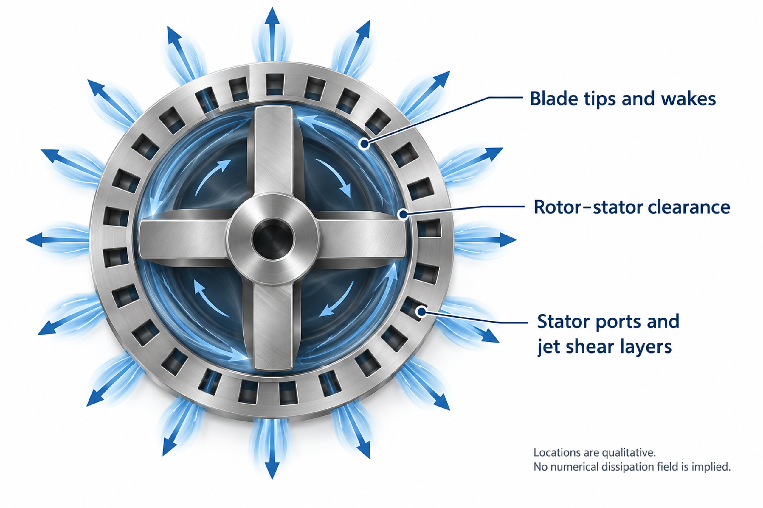
Figure 9.4. Qualitative diagram of regions of intense deformation and dissipation at blade tips, within the gap, and in stator jets. [1, 2, 3].
9.3 Mechanisms of Particle and Droplet Breakup in Rotor-Stator Mixers
Hydrodynamic loading must overcome either interparticle cohesive forces or capillary resistance to break agglomerates or deform droplets. Depending on structural strength and treatment intensity, breakup may occur through gradual surface erosion of agglomerates or rapid fragmentation into many smaller pieces. Bałdyga and Malik compare deagglomeration equipment using local energy dissipation and specific energy demand while considering the different mechanisms of stress generation. In rotor-stator machines operating without cavitation, breakup primarily results from hydrodynamic deformation, including shear and extension, which should not be confused with impact grinding in bead mills or abrasion of primary crystals [17].
U.S. Patent 6,000,840 provides illustrative empirical comparisons: median particle diameters of 9.7, 3.2, and 2.0 μm were reported for a high speed disperser, a conventional rotor-stator unit, and a specialized wedge rotor, respectively, while corresponding specific surface areas were 2.2, 3.3, and 5.2 m²/g. The patent also records changes in formulation and equipment settings between tests. These measurements therefore describe particular experimental runs, not a controlled isolation of rotor geometry at identical composition and specific energy input and cannot establish a universal ranking of equipment efficiency [9].
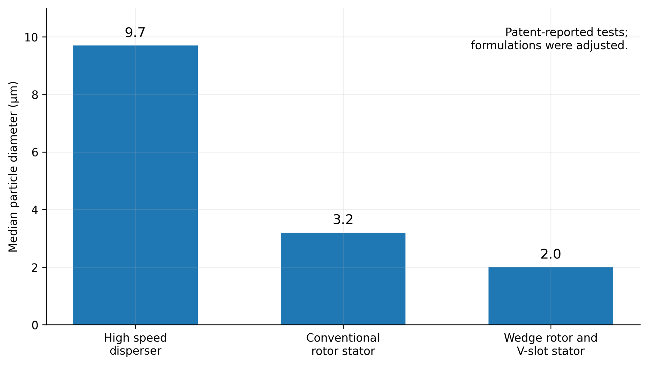
Figure 9.5. Median particle diameters reported in U.S. Patent 6,000,840. Corresponding specific surface areas were 2.2, 3.3, and 5.2 m²/g. Changes in composition and operating settings prevent interpretation as a universally controlled performance ranking [9].
The deagglomeration literature relates stronger processing to changes in the resulting agglomerate size distribution [17]. A separate calculation based on Equation (9.32) illustrates liquid droplet breakup and the sensitivity of inertial-range scaling to dissipation and interfacial tension. These curves are not Aerosil measurements, and a liquid droplet model cannot be applied directly to the cohesive strength of solid agglomerates.
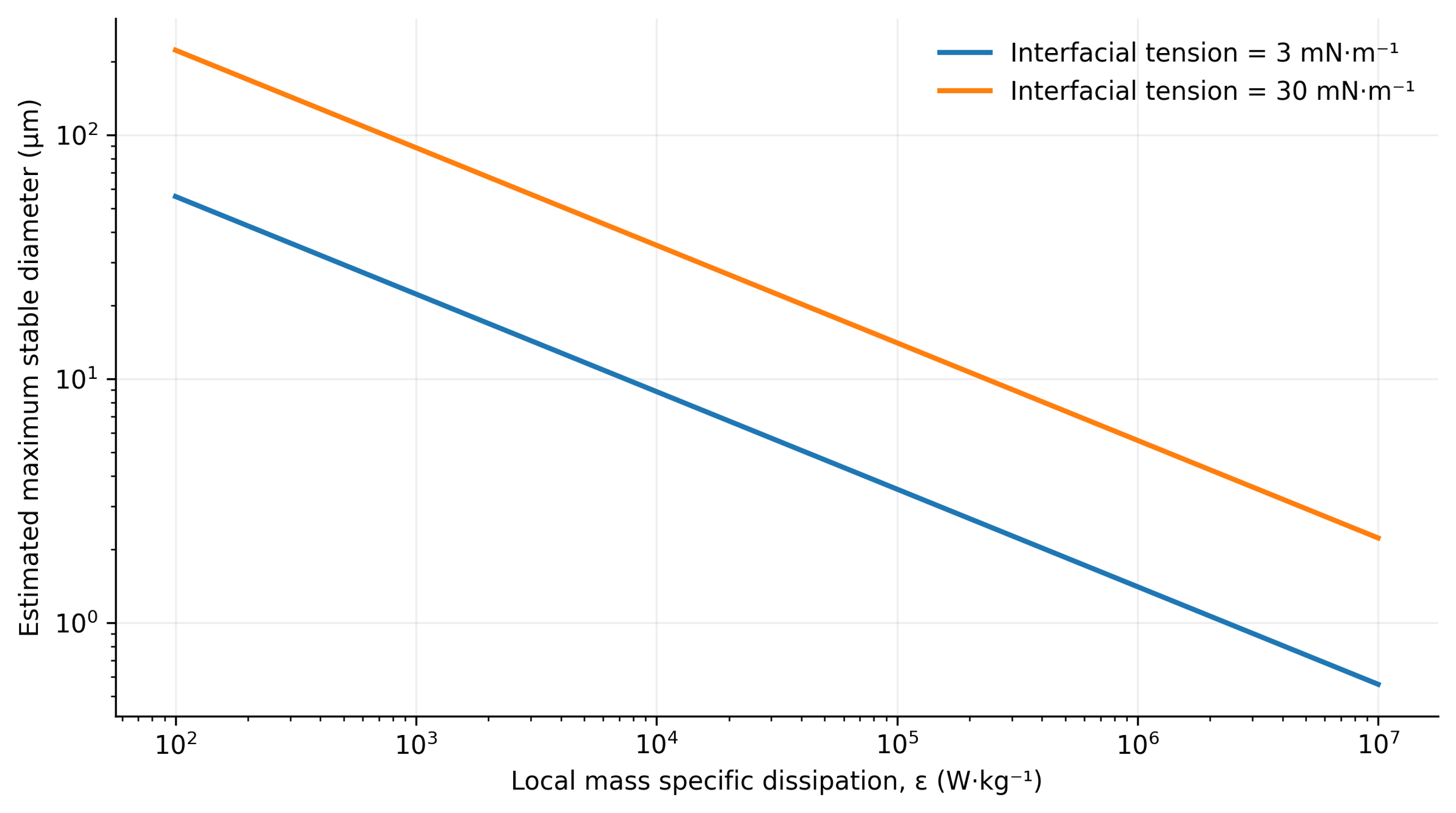
Figure 9.6. Calculated inertial-range scaling of maximum stable droplet diameter using Equation (9.32), with density 1000 kg/m³ and an illustrative coefficient Cₕ = 0.725 [1].
9.4 Hydrodynamic Cavitation in Rotor-Stator Mixers
Hydrodynamic cavitation involves nucleation and rapid growth of cavities containing vapor or gas in localized low-pressure regions, for example behind rotor blades, within rotor-stator gaps, or at the entrances to calibrated stator openings. Subsequent transport into higher pressure regions produces rapid condensation or collapse. Cavitation bubble collapse can generate strong pressure waves, high speed microjets, and extreme localized temperatures and pressures that may erode metallic working surfaces.
Dissolved gas and gas filled nuclei substantially influence cavitation dynamics, but expansion of a gas bubble is not necessarily equivalent to collapse of a vapor cavity. Under suitable conditions, controlled cavitation can intensify dispersion, homogenization, and interfacial mass transfer through highly localized energy release. Uncontrolled cavitation, however, can degrade hydraulic performance and cause unacceptable vibration, noise, and premature equipment wear. Analysis of pressure history of the flow and the location of bubble collapse is therefore more informative for process performance and safety than simply observing bubbles in the medium [18, 19, 20].
A simplified steady relation for mechanical energy can be used to compare two channel sections:
where p₁ and p₂ are static pressures, U₁ and U₂ are mean velocities, and Δpₗ represents irreversible pressure losses, including elevation effects when necessary.
This relation shows conversion between static pressure and kinetic energy in a channel but does not represent the complete energy balance of an operating rotor, which also involves shaft work, centrifugal effects, unsteadiness, and three-dimensional flow. A common dimensionless indicator of pressure margin is the cavitation number,
where σ꜀ is the cavitation number, pᵣₑꜰ is a reference absolute pressure, pᵥ is vapor pressure, and Uᵣₑꜰ is the chosen local reference velocity.
A lower value indicates less pressure margin relative to the selected velocity scale, not a universal cavitation threshold. The absolute reference pressure, temperature, vapor pressure, and velocity reference location must be reported. Nuclei concentration, dissolved gas, and surface condition can shift the onset even under nominally identical operating settings. Cavitation numbers should therefore be supplemented with local pressure measurements, validated simulations, or direct observation.
The radial motion of a spherical cavity in an incompressible liquid is described by the Rayleigh-Plesset equation:
where R is bubble radius; is pressure inside the bubble; p∞ is the far field liquid pressure; σ is surface tension; and dots denote differentiation with respect to time [18, 19, 20].
Using the Rayleigh-Plesset equation requires a model for internal bubble pressure and a specified or coupled calculation of the external pressure history. The equation alone does not predict nuclei concentration, asymmetric microjet formation, or interactions between neighboring bubbles. Its incompressible form is also insufficient to describe the final, strongly compressible phase of collapse in detail. These limitations are particularly significant when extrapolating a single bubble model to cavitation mixer performance [20].
For an initially stationary empty cavity collapsing under a constant positive pressure difference, Rayleigh's estimate of collapse time is
where t꜀ is collapse time and R₀ is the initial cavity radius [18].
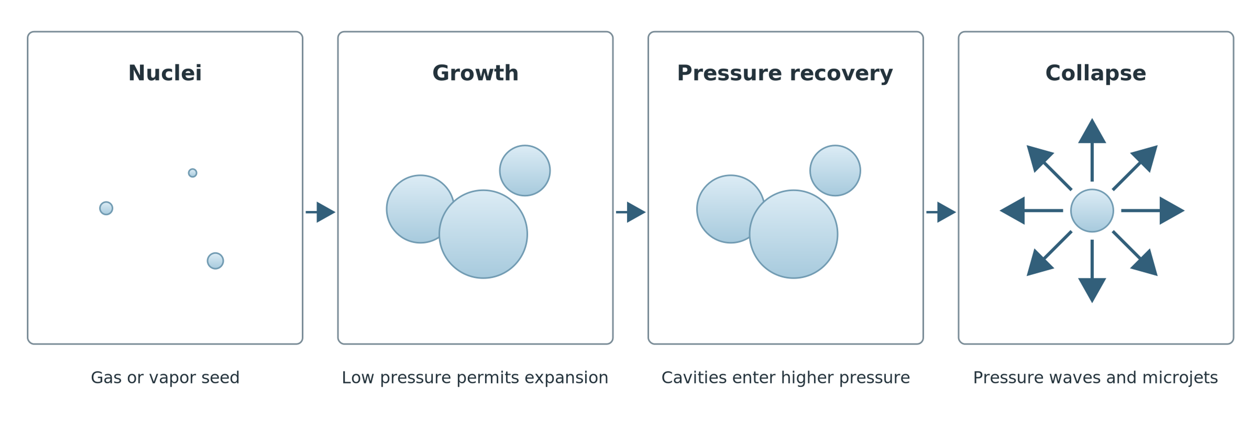
Figure 9.7. Cavity growth, transport to a region of pressure recovery, and collapse. [1].
Whereas an ordinary mixing head under sufficiently high static pressure can operate without cavitation even at high tip speeds, dedicated rotational cavitation reactors are designed specifically to create pronounced low pressure regions. Their working elements may incorporate profiled holes, grooves, pins, or features that promote flow separation that intensify local pressure variations. Zhang and colleagues demonstrated that hole geometry substantially affects vapor distribution, vortex structure, and pressure fluctuation amplitude in such reactors [21]. Their results establish sensitivity to the particular flow geometry examined but cannot be generalized into a universal cavitation law for all rotor-stator mixers.
Analytical and numerical estimates of cavity collapse dynamics often assume that a cavity starts from rest and experiences a constant positive driving pressure difference. In actual process fluids, collapse is strongly modified by factors including:
-
The presence of noncondensable gas in nuclei.
-
Fluid rheology and viscosity.
-
Interfacial surface tension.
-
The finite speed of sound in a two phase flow.
-
Proximity to solid boundaries such as chamber walls and rotor-stator surfaces.
Consequently, a calculated theoretical cavity-collapse time should not be presented as an experimentally measured event duration or used as a reliable quantitative predictor of erosive damage to structural materials [18, 19, 20, 21].
9.5 Acoustic Oscillations and Hydrodynamic Pressure Pulsations
Periodic interaction between moving rotor elements and stationary stator passages generates regular pressure oscillations even in a single phase incompressible liquid. Successive rotor teeth, blades, or holes pass stationary features at a characteristic element passage frequency, while nonlinear partial obstruction of the passages produces higher harmonics in the pressure spectrum.
Rotor-pulsation apparatuses deliberately exploit this flow modulation using toothed crowns, profiled channels, and concentric working rings to intensify mixing and dispersion [4, 5, 6, 7]. In spectral analysis, the resulting discrete tonal pressure signal must be distinguished from broadband high-frequency turbulence and the short pressure impulses produced by localized collapse of cavities containing vapor or gas.
Periodic rotor-stator interactions produce pressure oscillations even in single phase liquids. Repeating rotor features pass stationary openings at a characteristic frequency, while partial obstruction generates higher harmonics. Rotor-pulsation designs use teeth, channels, and working rings to create this modulation [4, 5, 6, 7]. The resulting signal must be distinguished from broadband turbulence and the impulsive components of bubble collapse.
A periodic pressure signal can be represented as the sum of a mean component and harmonics:
where p̄ is mean pressure, Aₖ is the amplitude of harmonic k, k is the harmonic index, and φₖ is its phase.
For the restricted case of a propagating plane acoustic wave, the mean sound intensity is estimated by
where I is sound intensity, pᵣₘₛ is root-mean-square acoustic pressure, ρ is density, and c is sound speed.
The plane wave expression is valid only under specific conditions. Pressure measured near a mixing head includes hydrodynamic fluctuations, reflections, and coupling to structural vibration; its total rms value cannot automatically be treated as the pressure of a propagating plane wave. The Strouhal number provides a separate measure comparing an observed frequency with a convective time scale:
where St is Strouhal number, f is frequency, L is a characteristic length, and U is a characteristic velocity.
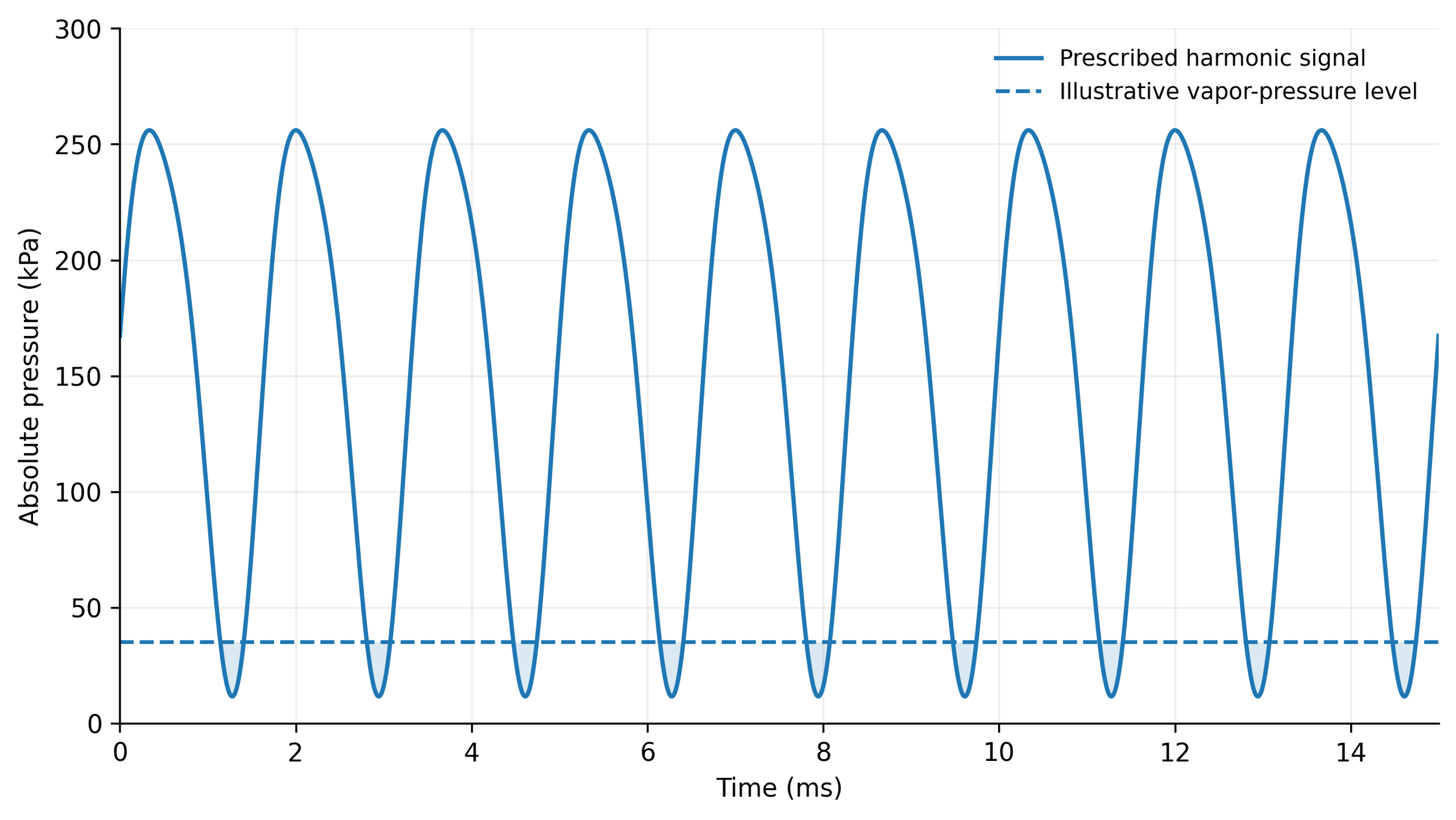
Figure 9.8. Illustrative harmonic pressure signal based on Equation (9.20): mean pressure 150 kPa, fundamental amplitude 120 kPa at 600 Hz, and a 20 kPa second harmonic with phase π/3. The 35 kPa reference level is illustrative; intervals below that level do not represent a calculated two-phase flow [1].
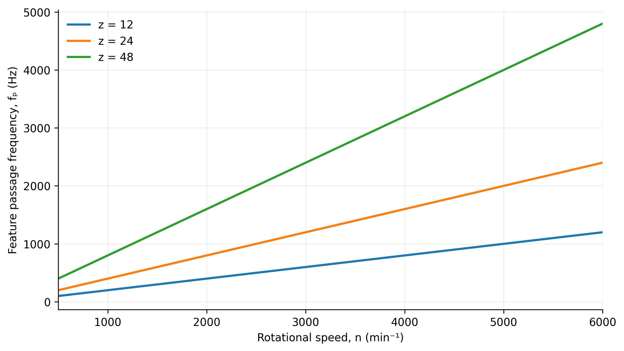
Figure 9.9. Calculated passage frequencies for 12, 24, and 48 repeating elements using Equation (2.3). The relation does not determine amplitude or additional spectral components [1].
A spectral maximum at the element passage frequency and its harmonics helps identify direct rotor forcing. Sidebands and broadband components must be interpreted in conjunction with operating conditions and the measurement system. In a rotational cavitation reactor studied by Zhang and colleagues, 24 circumferential openings produced a dominant frequency component equal to 24 times the shaft rotation frequency. Hole diameter influenced pressure amplitude in that specific geometry [21].
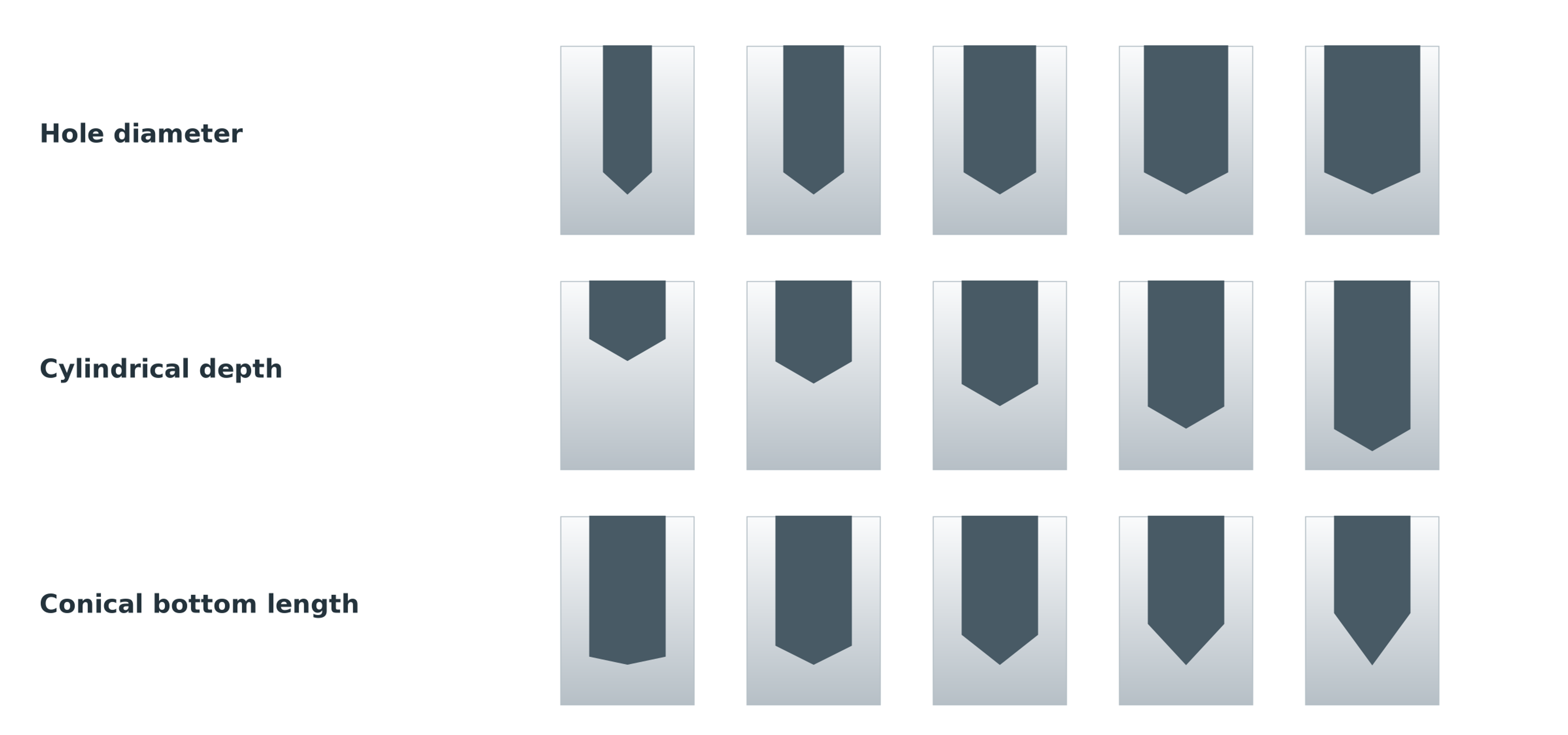
Figure 9.10. Families of hole geometries varying in diameter, cylindrical depth, and conical bottom length [21].
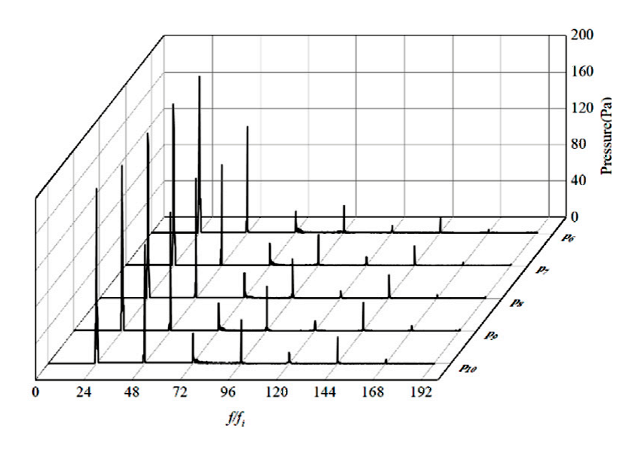
Figure 9.11. Published pressure spectra for the largest hole diameter, 19 mm, at five measurement locations. Reproduced under CC BY 4.0 [21].
The spectra in Figure 9.11 are a selected excerpt from a published study, not newly digitized experimental data. The original axes and curves are retained. The idealized harmonic wave shown elsewhere in this section illustrates a signal representation and is not a numerical simulation of two-phase cavitation.
9.6 Spatial and Temporal Scales of Turbulence and the Fine Structure of Dissipation
In strongly inertial flows, separation at rotor blade edges and high-velocity jets leaving stator openings produce fluctuations over a broad range of spatial and temporal scales. Energy dissipation is markedly nonuniform and intermittent within rotor-stator mixers. Integral measures averaged over the tank therefore cannot represent the extreme local mechanical loading in the narrowest gaps or at stator exits. In Rueger's tested inline geometry, the peak local dissipation rate was approximately nine times the average over the mixer. That observation concerns a particular design and cannot be extrapolated as a universal correction factor [2, 3].
Kolmogorov microscales are used to describe the small scale structure of turbulence and local micromixing in high shear regions. The Kolmogorov length scale () characterizes the smallest eddies where kinetic energy is dissipated viscously and is defined by
where η is Kolmogorov length scale, ν is kinematic viscosity, and ε is local specific energy dissipation rate.
where τᵨ is Kolmogorov time scale.
where uᵨ is Kolmogorov velocity scale [22].
For a passive scalar in the viscous-convective regime at high Schmidt number, the Batchelor scale is
where is the smallest scalar diffusion scale and Sc is the ratio of kinematic viscosity to molecular diffusivity [23].
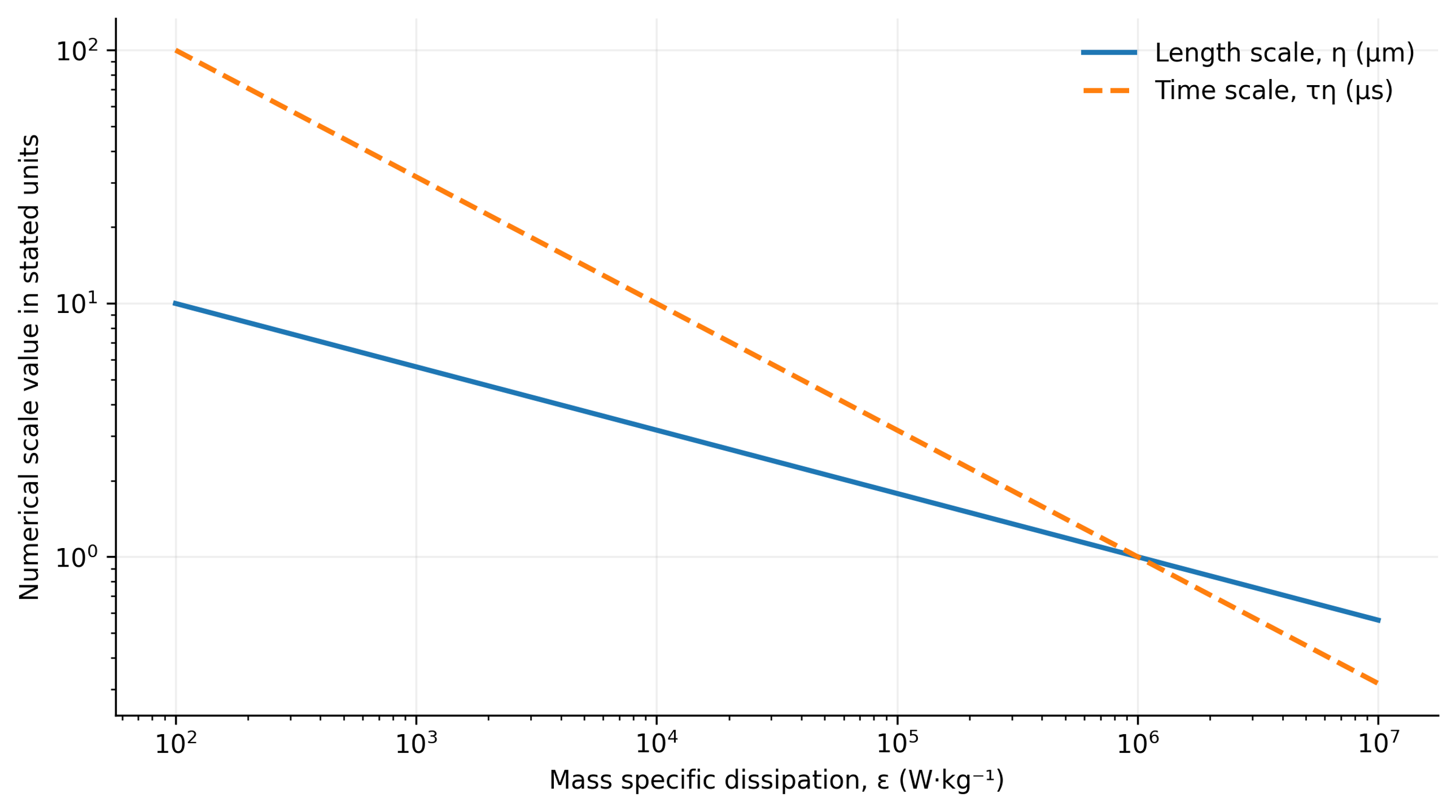
Figure 9.12. Calculated Kolmogorov length and time scales at kinematic viscosity 1.0 × 10⁻⁶ m²/s, using Equations (9.23) and (9.24) [1].
Although fundamental, the Kolmogorov and Batchelor scales describe idealized local turbulence and passive scalar diffusion. They cannot be equated directly with the minimum achievable droplet or solid particle diameter in real dispersions. Use of these scales requires validation of flow assumptions and explicit local dissipation averaging. The Batchelor relation is not a universal mixing length at small Schmidt numbers (), or in polydisperse materials with complex rheology such as viscoelasticity or yield stress.
For a droplet or solid particle of diameter () lying in the inertial subrange of developed turbulence, dynamic stress induced by velocity fluctuations at eddies of comparable size can be estimated from Kolmogorov-Obukhov scaling:
For a particle or droplet in the inertial subrange, stress at the eddy scale is approximated by
where τᵢ is the inertial stress at scale d and Cᵢ is a coefficient of order unity.
For an object smaller than the Kolmogorov length, viscous stress at the smallest turbulent scale can be estimated by
where τᵥ is viscous microscale stress and Cᵥ is a coefficient dependent on the stress definition.
These relationships provide a basis for balancing disruptive hydrodynamic forces against capillary and viscous restoring forces in models of emulsification and deagglomeration.
9.7 Droplet Breakup, Interfacial Area, and Micromixing
In emulsification and dispersion processes, the breakup of liquid droplets, formation of interfacial area, and micromixing depend on the balance between externally applied hydrodynamic deformation and internal capillary restoring forces.
For a droplet in developed inertial turbulence, the primary dimensionless criterion comparing disruptive fluctuating stresses with interfacial tension is the droplet Weber number:
where Weᵈ is droplet Weber number, d is droplet diameter, and σᵢ is interfacial tension.
For viscous shear, the corresponding parameter is the capillary number,
where Ca is capillary number and μ is continuous-phase viscosity.
The Ohnesorge number describes the influence of dispersed-phase viscosity:
where Oh is Ohnesorge number, and μᵈ and ρᵈ are dispersed-phase viscosity and density.
Equating turbulent inertial loading with capillary restoring forces yields a scaling relation for the maximum stable droplet diameter:
where dₘₐₓ is the maximum stable droplet diameter and Cₕ is an empirical coefficient. The expression is a scaling relation, not a universal calibration of mixer performance.
This relation describes an illustrative scaling behavior of emulsification rather than a universally calibrated mixer model. The empirical coefficient and the critical breakup conditions depend on the mathematical definitions, data analysis methods, and rheological properties of the phases. The relation is most appropriate for droplets within the inertial subrange, provided that dispersed-phase viscosity, confinement, and recoalescence do not dominate.
In practice, maximum stable droplet diameter () must not be equated with Sauter mean diameter () without a statistical model for droplet size distribution. If creation and stabilization of fresh interfaces occur on the time scale of hydrodynamic exposure, dynamic rather than equilibrium interfacial tension becomes important.
The Sauter mean diameter relates dispersed-phase volume to interfacial area through the number distribution:
where nᵢ is the number of droplets in size class i and dᵢ is the diameter of that class.
For spherical droplets with dispersed-phase volume fraction φᵈ, the interfacial area per unit mixture volume is
Where a is the specific interfacial area per unit mixture volume.
The same area relationship applies to a polydisperse set of spherical droplets if d₃₂ is calculated from the moments of the number distribution. This follows directly from summing the surface areas and volumes of spheres. No sphericity, inaccessible surfaces, and uncertainty in the dispersed phase volume fraction require separate consideration; a single diameter measurement does not determine the actual accessible interfacial area.
A common estimate of micromixing time uses the smallest turbulent time scale:
where tᵨ is micromixing time and Cᵨ is a model coefficient.
The relationships link local deformation, interfacial properties, and exposure time with the expected processing outcome. They do not, however, close the model for an evolving size distribution. Breakup competes with coalescence, adsorption, and transport, while rheological changes alter the flow itself. Once a useful limiting state is approached, further processing mainly increases heating and wear. The preferred operating target is therefore the minimum reproducible energy dose meeting product requirements, not maximum treatment duration.
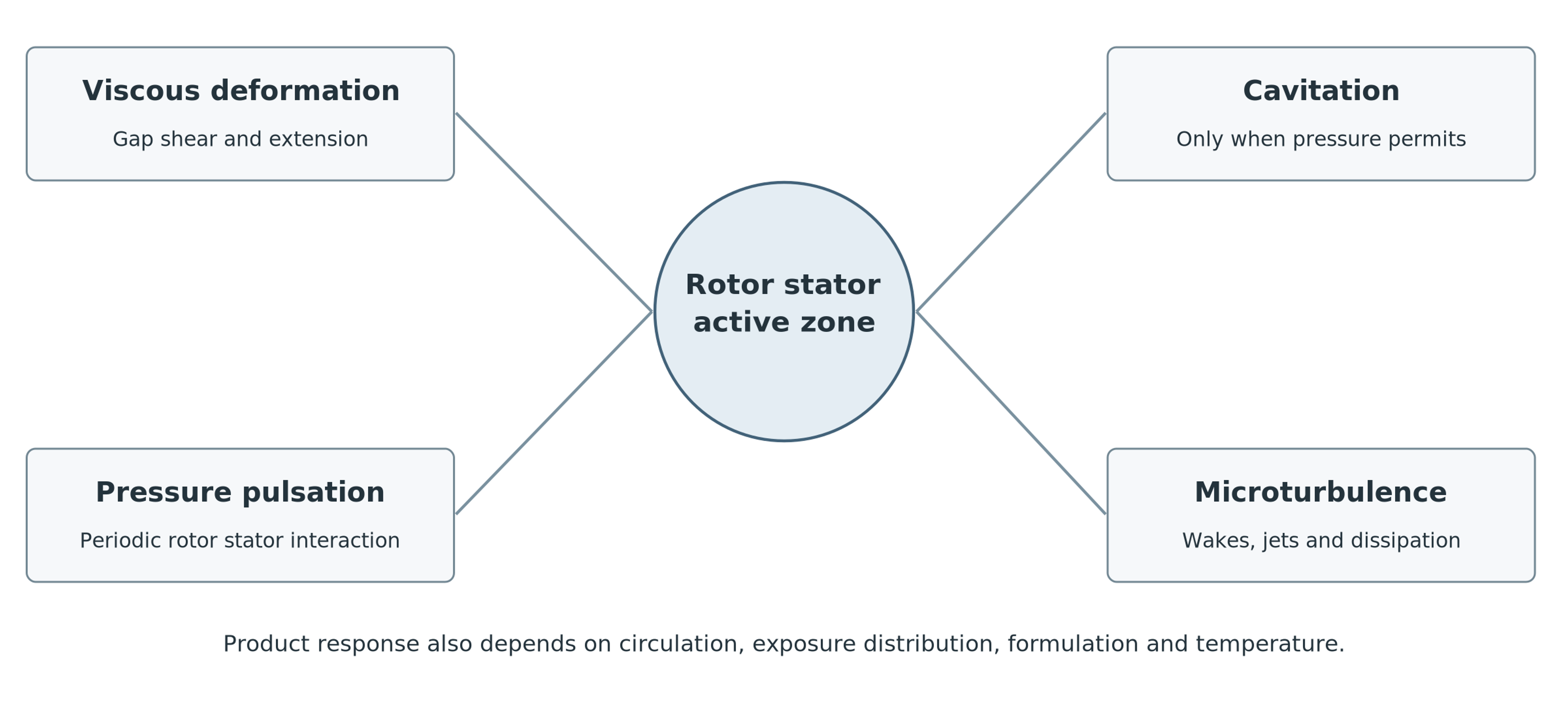
Figure 9.13. Mechanisms that may operate within the active region of a rotor-stator mixer. Their relative contributions depend on geometry, material properties, and operating conditions [1].
Table 9.1. Mechanisms of action and their characteristic observable indicators
| Mechanism | Physical cause | Observable indicators | Design controls |
|---|---|---|---|
| Intense shear | High velocity gradients and extensional deformation in gaps, at edges, and within jets. | Torque, rheological response, and droplet or agglomerate breakup without cavitation noise. | Tip speed, clearance, blade shape, stator restriction, and viscosity. |
| Hydrodynamic cavitation | Vapor cavities form at low pressure and collapse after pressure recovery; gas nuclei alter the dynamics. | Broadband noise, vapor clouds, erosion, pressure minima, and radical formation in suitable liquids. | Absolute pressure, temperature, geometry, dissolved gas, cavitation number, and backpressure. |
| Pressure pulsations | Periodic rotor-stator passage with time varying open flow area. | Discrete spectral peaks at element passage frequency and its harmonics. | Element count, relative phase, opening area, speed, and housing compliance. |
| Small-scale turbulence | Breakdown of wakes and jets into fluctuating eddies with intermittent dissipation. | Broad velocity spectrum, rapid micromixing, and power dependent on the Reynolds number. | Reynolds number, jet velocity, hole pitch, staging, and local dissipation. |
| Impact and cutting | Direct contact with leading edges or hard inclusions. | Fragmentation of soft particles, edge wear, and dependence on initial particle size. | Edge profile, feed direction, particle hardness, and clearance. |
| Acoustic streaming | Mean flow induced by oscillations of pressure and velocity. | Secondary circulation and transport beyond a steady-flow prediction. | Amplitude, frequency, chamber geometry, and damping. |
9.8 Mathematical Model Closure and Computational Validation of Hydrodynamic Processes
The analytical relations presented above form a hierarchy of descriptors and conditional models. Kinematic equations define speed scales and event frequencies; energy balances describe total power input and thermal dose; and rheological, turbulence, and cavitation models require detailed local flow conditions and constitutive closures. Final droplet or particle size distributions cannot be predicted using only bulk variables such as rotor tip speed or installed motor power. Reliable breakup and coalescence kinetic parameters, statistics of hydrodynamic exposure, and well-defined initial conditions are also required.
Computational fluid dynamics (CFD) models should first reproduce integral performance at the actual operating point, including flow rate, torque, and differential pressure. Mesh and sensitivity analyses of the time step are essential around narrow gaps and perforations. Rotor-stator phase interactions require transient techniques, such as sliding meshes. Local dissipation fields must be accompanied by the averaging volumes and time windows used to derive them. Attractive colored contours do not replace numerical validation, and turbulent dissipation predicted by a closure model must not be equated directly with locally measured stresses [3].
Lebon and colleagues compared stator perforation configurations in batch and inline high shear conditioning of metal melts. Their simulations showed that geometry optimized for local agglomerate breakup might distribute material poorly, and that predictions were sensitive to turbulence model choice [8]. This supports process specific design, but numerical coefficients and material responses determined for those media cannot be transferred directly to fundamentally different systems, such as oil-in-water emulsions.
Mathematical models should therefore be validated hierarchically at three levels:
-
Global level: Verify overall equipment balances, including flow rate, pressure head, and power consumption.
-
Local level: Model and corroborate the hydrodynamic mechanisms operating within the active region.
-
Product level: Compare predicted process characteristics against actual properties of the finished product.
Calibrating dispersion models against only one averaged diameter can conceal compensating errors in local dissipation, residence time, and coalescence. Reliable validation of model transferability requires experiments over different rotational speeds and throughputs, complete size distributions, and a recorded thermal history.
10. Effects of Design and Operating Parameters on Rotor-Stator Performance
Engineering design and selection of rotor-stator equipment require simultaneous consideration of working element geometry, flow hydrodynamics, material rheology, and thermal history. A technically sound specification begins by defining the desired transformation, such as deagglomeration, fine emulsification, or homogenization, and identifying the dominant mechanism responsible. Selecting equipment solely by installed motor power is methodologically inadequate: it may deliver vigorous bulk circulation without sufficient local shear stress, or very intense treatment of only a small portion of the material while leaving poor overall exchange and stagnant regions.
Different features of the working pair control distinct aspects of mixer performance:
-
Radial clearance: Reducing the gap increases nominal velocity gradient and local shear stresses but also raises flow resistance, reduces tolerance to accidental solids, and increases sensitivity to differential thermal expansion of the rotor and stator.
-
Open area and hole geometry: Changing the free area and profile of stator passages directly affects jet velocity, hydraulic losses, and the characteristic scales of turbulent eddies.
-
Number of repeating elements: Increasing the number of teeth, blades, or openings raises the passage frequency and high-frequency pressure modulation. However, pressure amplitude does not necessarily increase proportionally because throughput limits and hydrodynamic blockage also affect the flow.
-
Active radius: Changing working element diameter changes tip speed and centrifugal forces and therefore influences the overall power potential of the machine.
Where hydrodynamic cavitation or controlled phase transitions are the intended dominant mechanism, operating parameters such as static pressure, backpressure, and fluid temperature must be independently controlled to avoid unstable operation, excessive thermal degradation, or uncontrolled equipment erosion.
Table 10.1. Principal dimensionless criteria
| Criterion | Definition | Principal physical meaning |
|---|---|---|
| Rotor Reynolds number | Equation (9.4) | Balance of inertial and viscous effects at the rotor scale. |
| Gap Reynolds number Reg | Equation (9.5) | Balance of inertia and viscosity in the clearance. |
| Power number Po | Equation (9.7) | Dimensionless liquid power for geometric and dynamic similarity. |
| Flow coefficient Φ | Equation (9.8) | Pumping or flow rate normalized by rotor speed and diameter. |
| Pressure coefficient Ψ | Equation (9.9) | Pressure rise or loss relative to dynamic pressure at the rotor scale. |
| Cavitation number | Equation (9.17) | Pressure margin above vapor pressure relative to dynamic pressure. |
| Strouhal number St | Equation (9.22) | Oscillation frequency relative to a convective time scale. |
| Droplet Weber number Wed | Equation (9.29) | Turbulent deformation relative to interfacial tension. |
| Capillary number Ca | Equation (9.30) | Viscous deformation relative to interfacial tension. |
| Ohnesorge number Oh | Equation (9.31) | Effect of dispersed phase viscosity relative to inertia and capillarity. |
Table 10.2. Design parameters and expected effects
| Parameter | Typical effect of increasing the parameter | Possible adverse effect |
|---|---|---|
| Rotor speed | Increases tip speed, event frequency, power, shear, and turbulence. | Rapid heating, seal loads, vibration, erosion, and air entrainment. |
| Rotor diameter | Increases tip speed and sharply increases turbulent power at constant rpm. | Higher torque and mechanical stresses; scale up errors at constant rpm. |
| Smaller clearance | Increases nominal shear rate and pressure gradient. | Contact risk, resistance, heating, wear, and particle blockage. |
| Smaller stator openings | Increases edge length and jet velocity at fixed throughput. | Pressure loss, clogging, and reduced pumping capacity. |
| Additional stages | Increases accumulated mechanical exposure per pass. | Heating, pressure loss, cleaning difficulties, and overprocessing. |
| Higher backpressure | Can suppress cavitation and stabilize complete liquid filling. | Greater seal and housing loads, potentially more power or lower flow. |
| Higher temperature | Often decreases viscosity and interfacial tension. | Higher vapor pressure, cavitation tendency, and degradation rate. |
| Higher viscosity | Increases viscous stress at a given shear rate. | Lower flow, higher torque, and weaker turbulence. |
| Higher gas content | Increases nuclei and may promote earlier cavitation onset. | Foaming, reduced pumping, oxidation, and unstable power. |
| Higher solids loading | More particle contacts and greater solids mass per mixture volume. | Higher viscosity, plugging, abrasive wear, and incomplete wetting. |
10.1 Numerical Example and System Sensitivity Assessment
The following hypothetical numerical example concerns a recirculating process using a continuous liquid phase with properties close to those of water. It is provided solely to illustrate the engineering method; it is not an official specification or a performance guarantee for equipment from Scott Turbon, IKA, Silverson, Kinematica, or any other manufacturer.
The active deformation zone volume and the share of input power dissipated within that volume are assumed for sensitivity analysis rather than measured. Table 10.3 lists the adopted parameters for a model in which fluid properties and volumetric flow rate remain constant throughout the processing cycle.
Table 10.3. Assumed input data for the numerical example
| Quantity | Assumed value | Explanation |
|---|---|---|
| Rotor diameter D; speed n | 0.100 m; 3000 min⁻¹ | N = 50 s⁻¹; chosen to illustrate the operating condition. |
| Effective gap g; element count z | 0.50 mm; 24 | Relative gap velocity approximated by rotor tip speed. |
| Flow Q; tank volume VT; time t | 0.0020 m³·s⁻¹; 0.50 m³; 600 s | Constant-flow recirculation through an ideally mixed tank. |
| Active volume Va | 2.0 × 10⁻⁵ m³ | 20 mL; assumed averaging region, not a measured machine volume. |
| Density ρ; viscosity μ | 1000 kg·m⁻³; 0.0010 Pa·s | Newtonian liquid with constant physical properties. |
| Specific heat capacity cp | 4180 J·kg⁻¹·K⁻¹ | No phase transitions or heat removal in the temperature estimate. |
| Shaft power Ps; dissipated power Pdiss | 3.10 kW; 3.00 kW | 60 W mechanical losses and 40 W useful hydraulic power. |
| Pressure rise Δp | 20 kPa | Positive pressure rise at the specified flow rate. |
| Power dissipated in active zone Ploc | 2.10 kW | Assumed to be 70% of power dissipated in the liquid. |
| Reference pressure pref; vapor pressure pv | 150 kPa absolute; 2.34 kPa | Assumed values for the illustrative cavitation number. |
| Interfacial tension σi; coefficient CH | 0.030 N·m⁻¹; 0.725 | Illustrative inertial-range droplet scaling, not a calibrated prediction. |
At the specified shaft power, calculated torque is 9.87 N·m. Rotor tip speed is 15.71 m/s, nominal gap shear rate is 3.14 × 10⁴ s⁻¹, and element passage frequency is 1200 Hz. These are kinematic results, not measurements of local stress distributions. The rotor Reynolds number is 5.00 × 10⁵, and the gap Reynolds number at the assumed relative velocity is 7.85 × 10³.
Table 10.4. Calculated characteristics of the example
| Quantity | Calculated result | Equation |
|---|---|---|
| Rotor tip speed Ut | 15.71 m·s⁻¹ | (2.2) |
| Element passage frequency fp | 1200 Hz | (2.3) |
| Nominal gap shear rate | 3.14 × 10⁴ s⁻¹ | (9.1) |
| Rotor and gap Reynolds numbers | 5.00 × 10⁵; 7.85 × 10³ | (9.4), (9.5) |
| Torque T | 9.87 N·m | (9.6) |
| Power number Po; flow coefficient Φ | 2.40; 0.040 | (9.7), (9.8) |
| Pressure coefficient Ψ; hydraulic ratio | 0.80; 1.29% | (9.9), (9.10) |
| Nominal residence time in the active zone | 0.010 s | (3.1) |
| Mean equivalent pass count | 2.40 | (3.2) |
| Mean specific dissipation rate in the tank | 6.00 W·kg⁻¹ | (9.11) |
| Volumetric dissipation rate in the active zone | 1.05 × 10⁸ W·m⁻³ | (9.12) |
| Specific dissipation rate in the active zone | 1.05 × 10⁵ W·kg⁻¹ | (9.11), using Ploc and Va |
| Energy per unit volume per pass | 1.50 MJ·m⁻³ | (9.13) |
| Nominal accumulated batch dose | 3.60 MJ·m⁻³ | (9.14) |
| Adiabatic heating per pass; after 600 s | 0.359 K; 0.861 K | (9.15) |
| Reference cavitation number | 1.20 | (9.17) |
| Local Kolmogorov length η and time | 1.76 µm; 3.09 µs | (9.23), (9.24) |
| Local Kolmogorov velocity | 0.569 m·s⁻¹ | (9.25) |
| Illustrative maximum stable diameter dmax | 13.7 µm | (9.32) |
In this numerical example, the specific mechanical energy is 1.50 kJ/kg per pass through the active region and 3.60 kJ/kg after 600 s of recirculation. Multiplying the energy per pass by the mean equivalent pass count yields the total nominal accumulated energy dose and provides an internal consistency check on the energy balance. The process time scales differ substantially: nominal residence time in the high intensity active region is about 10 ms, whereas a complete turnover of the 0.50 m³ tank requires roughly 250 s. This large separation demonstrates why one mean residence time, or average dissipation rate cannot characterize the whole system. In the assumed configuration, the specific dissipation rate in the active zone is approximately 17,500 times the tank average. This ratio follows from the stipulated zone volume and allocation of power; it is not a universal measured amplification factor. The maximum stable droplet diameter estimated from inertial-range scaling is about 7.8 times the local Kolmogorov length. Although this ratio permits an illustrative scaling calculation, it does not establish that a developed inertial subrange exists or provide a reliable prediction of a real emulsion's droplet distribution. The example deliberately omits dispersed-phase viscosity, component volume fractions, interfacial stabilization kinetics, and recoalescence. The cavitation number, based on the specified reference static pressure and rotor tip speed, is 1.20. This value alone does not establish whether cavitation occurs, because local pressure minima and the actual distribution of gas nuclei are unknown. Finally, an idealized independent-pass model predicts that, at a mean pass count of 2.4, approximately 9.1% of the liquid has not passed through the mixing head at all. This probabilistic result assumes instantaneous ideal tank mixing and does not replace experimental validation of the recirculation circuit.
10.2 Sensitivity and Uncertainty Analysis
At constant diameter and power number, doubling rotational speed doubles tip speed, nominal shear rate, and element passage frequency while increasing dissipated power eightfold. At fixed flow rate, energy per pass and the corresponding adiabatic temperature rise also increase eightfold. If volume of the active zone and its share of dissipated power remain unchanged, the estimated inertial-range droplet diameter decreases to approximately 0.435 of its initial value. These are consequences of the assumed scaling relations, not evidence that the flow regime or power number will actually remain constant at the new speed.
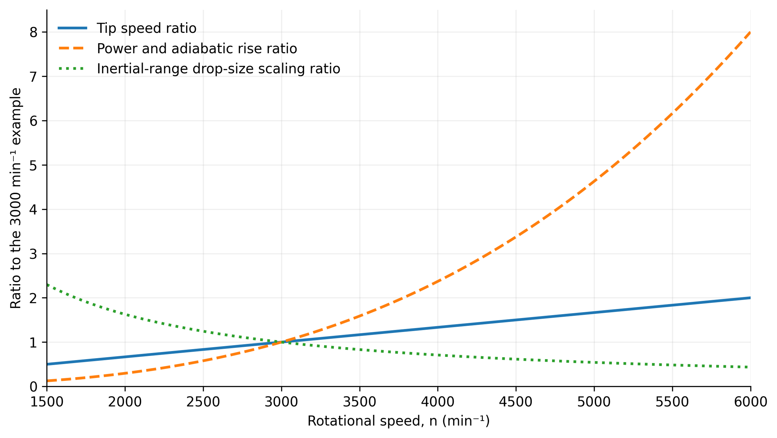
Figure 10.1. Calculated sensitivity relative to the 3000 min⁻¹ reference case. Diameter, throughput, liquid properties, power number, volume of the active zone, and local power fraction are held constant. The curves represent assumed scaling laws, not measured equipment performance [1].
Uncertainty in volume of the active zone can dominate local calculation. A twofold change in local dissipation changes the inertial range droplet diameter estimate by a factor of 0.758, whereas doubling interfacial tension increases it by approximately 1.52. These sensitivities identify the most useful measurements. Geometry specific power data, material properties at processing conditions, and a defensible definition of the active region are more informative than a nominal shear rate reported with unwarranted numerical precision.
11. Challenges and Principles of Scaling Up Rotor-Stator Mixers
Scaling a rotor-stator process from laboratory or pilot conditions to industrial production is difficult because no single similarity criterion can preserve every relevant physical mechanism. Constant tip speed preserves the velocity at the rotor perimeter, while constant power per unit volume preserves only an average measure of energetic intensity. Maintaining nominal shear rate requires a constant ratio between relative velocity and gap width, whereas residence time depends on the ratio of active volume to volumetric flow. Cavitation similarity additionally requires compatible static pressures and thermal conditions governing vaporization. The appropriate scale up criterion must therefore be selected by identifying the process mechanism that limits attainment of the target product quality.
For geometrically similar turbine and rotor-stator systems operating in developed turbulence at constant power number () and fluid density (), the power () follows the standard scaling relation:
where is rotational frequency and is rotor diameter.
If constant rotor tip speed () is selected as the similarity criterion, rotational frequency becomes inversely proportional to diameter (). Substitution into the power relation shows that power is proportional to the square of diameter:
Under geometric similarity, working volume grows in proportion to the cube of diameter (). Therefore, mean power per unit volume () decreases inversely with diameter () during scale up. It is thus impossible to preserve both constant tip speed and constant volumetric dissipation intensity under unrestricted geometric enlargement.
Modern modular inline systems can increase throughput by enlarging the open flow area, arranging devices in parallel, or changing the number of consecutive processing stages. Maintaining product quality requires preservation of the relevant local hydrodynamic conditions and their exposure distribution. Empirical correlations relating process performance to effective diameter and stage count are valid only within the range for which they were calibrated [2]. Experience with transitions from batch to continuous rotor-stator operation also cautions against transferring results solely because the nominal head design appears similar, without accounting for different velocity fields and residence times [12].
Table 11.1. Scale up criteria and characteristics approximately preserved
| Criterion | Approximately preserves | Does not automatically preserve |
|---|---|---|
| Constant rotor tip speed | Surface velocity and some blade loading. | Power per unit volume, passage frequency, residence time, and gap shear rate. |
| Constant nominal shear rate | Velocity gradient Urel/g. | Turbulence, pumping, cavitation, and exposure probability. |
| Constant power per unit volume | Average energy dissipation rate. | Peak local dissipation, flow structure, and element passage frequency. |
| Constant energy per unit volume | Accumulated mechanical energy dose. | Instantaneous stress and breakup threshold. |
| Constant Reynolds number | Dynamic similarity of viscous and inertial forces. | Similarity of cavitation, free surface, and dispersed phase. |
| Constant cavitation number | Pressure margin relative to dynamic pressure. | Nuclei concentration, dissolved gas, and collapse conditions. |
| Constant residence time | Nominal duration of exposure in an inline unit. | Local stress distribution and internal head recirculation. |
| Constant number of passes | Mean dose during recirculation. | Uniform treatment in a nonideally mixed tank. |
11.1 Recommended Sequence and Procedure for Scale Up
A defensible scale up strategy first seeks to preserve the dominant local mechanism responsible for product quality, followed by separate verification of global mass and heat transport. The principal similarity criterion depends on the process application:
-
Emulsification and dispersion: Rotor tip speed or local kinetic energy dissipation rate is often selected as the primary similarity measure, together with comparable interfacial properties and estimated residence time within the active zone.
-
Powder wetting and incorporation: Important limitations include pumping coefficient, suction at the working zone inlet, and the intensity of bulk circulation throughout the vessel.
-
Cavitation processes: In addition to geometric and kinematic similarity, absolute static pressure, operating temperature, cavitation producing geometry, and the local cavitation number must be appropriately controlled.
Pilot trials and industrial scale up should proceed in two stages. First, the dominant local treatment mechanism is preserved. Second, bulk transport, throughput, and the thermal balance are verified independently.
Transferring processes between equipment sizes on the basis of a common analytically defined product quality criterion is more reliable than using only a single empirical mean mixing time.
12. Criteria and Principles for Selecting Rotor-Stator Equipment
Equipment selection should begin with the rate limiting process step. Attempting to apply one mixer configuration throughout every stage of a process may reduce overall efficiency. Dry powders first require effective wetting, initial deagglomeration, and transport into the liquid; fine finishing screens are most appropriate after those steps. For a stable premix that requires additional droplet reduction, a high gradient generator or multistage system may be appropriate. In highly viscous products, feed supply and bulk tank circulation may be more limiting than local velocity gradient. Intentional cavitation must be justified by experimentally verified pressure conditions and a defined collapse region rather than a general high shear designation.
Feed properties, including initial particle size, deformability, and abrasiveness, must be evaluated against actual passage dimensions such as gaps, channel profiles, and perforation diameters:
-
Fibrous inclusions: May wrap around moving elements, cause jamming, and partially obstruct stator passages.
-
Hard abrasive particles: Cause abrasive wear and contact damage to precision rotor-stator surfaces.
-
Changes in solids concentration: Alter fluid rheology, hydraulic resistance, and the machine head versus flow characteristic.
For temperature-sensitive materials, limits on thermal exposure are critical. Controlled pass counts with efficient external heat exchange are preferable to prolonged, uncontrolled recirculation. These considerations support preliminary design, but final operating limits must be established by representative pilot-scale experiments.
Selection should begin with the limiting process step. Powder at the liquid surface must first be wetted and incorporated before a restrictive fine dispersion screen is introduced. A stable premix requiring further droplet reduction may benefit from a fine generator or an additional stage. For viscous products, material delivery and tank turnover may be limiting. Intentional cavitation requires confirmed pressure conditions and a suitable collapse zone, not merely a high-shear designation.
Initial particle size, deformability, and abrasiveness must be compared with actual openings and gaps. Fibers may block passages, hard inclusions may cause contact damage, and variations in solids content may change the head versus flow curve. Temperature sensitive products may benefit from controlled passages with external cooling rather than extended recirculation. These are preliminary design considerations; the allowable operating range must be established through representative product tests.
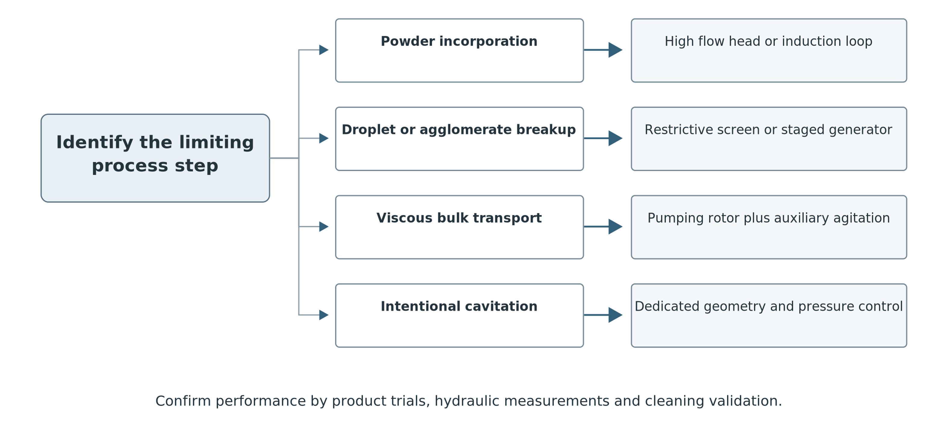
Figure 12.1. Qualitative equipment selection logic based on the limiting process stage. [1].
Table 12.1. Initial equipment selection recommendations for different process duties
| Process objective | Recommended initial geometry | Verification test |
|---|---|---|
| Rapid powder wetting | Open high throughput batch head, powder induction loop, or coarse inline stage. | Time for complete addition without dry lumps, floating powder, or air entrainment. |
| Polymer hydration | High capacity head followed by moderate shear after wetting. | Viscosity buildup, residual gel particles, and temperature rise. |
| Fine liquid-liquid emulsion | Finely perforated stator or multistage inline head. | Sauter diameter d32, distribution width, recoalescence on storage, and energy per unit volume. |
| Pigment or nanoparticle deagglomeration | High stress rotor-stator assembly, potentially multistage, with controlled viscosity. | Final agglomerate size, color intensity or specific surface area relative to energy consumed. |
| Breakup of soft solid inclusions | Slotted stator and cutting rotor. | Maximum feed size, fragment size distribution, and susceptibility to blockage. |
| Viscous food product texturing | Shear pump or coarse multiring head. | Texture, throughput, torque, and temperature history. |
| Rotor-pulsation treatment | Toothed or channeled rotor with phase-matched stator. | Pressure spectrum, passage frequency, and product response. |
| Hydrodynamic cavitation | Dedicated cavities, holes, pins, or grooves with pressure control. | Cavitation onset, vapor distribution, erosion rate, and process yield. |
| Hygienic multiproduct operation | Easy to disassemble or CIP capable head with verified drainability. | Cleaning solution coverage, residual contamination, and product-specific cleaning validation. |
12.1 Methodology for Planning Application-Specific Trials
Experimental programs for rotor-stator equipment must distinguish clearly between process objectives and identify the limiting physicochemical stages. A single universal testing protocol can give misleading results because hydrodynamic requirements differ substantially between heterogeneous systems.
-
Powder wetting and polymer hydration: Trials should document ingredient feed rate and location, time-dependent viscosity, and the residual amount of unwetted material. The ability to induct dry powder at the beginning of a process and to maintain circulation after the mixture has thickened are distinct design requirements. A fine finishing screen cannot compensate for inadequate inlet suction or poor incorporation geometry.
-
Emulsification: Full droplet size distributions should be compared at controlled phase volume fractions, stabilizer concentrations and types, and thermal conditions. Samples collected immediately after the head and again after a defined holding period distinguish breakup during processing from subsequent recoalescence. Long-term storage stability depends on the overall formulation chemistry and cannot be guaranteed by a high instantaneous shear rate alone.
-
Solid and pigment dispersion: Before testing, the desired outcome must be defined, whether it involves breaking agglomerates to a specified size, releasing primary particles, developing color intensity, attaining a target specific surface area, or producing a particular rheological structure. These objectives require different exposure histories. The deagglomeration classification proposed by Bałdyga and Malik provides a useful framework [17]. Specific mechanical energy input should always be evaluated against a measured benefit and the mass of treated product.
13. Mechanical Reliability, Hygiene, and Industrial Equipment Safety
Long service life, reliable operation, and hygienic safety require consideration of mechanical, hydrodynamic, and material factors throughout equipment design and operation.
13.1 Mechanical Clearances and Assembly Precision
The rotor-stator operating clearance must remain positive under all permissible conditions. Shaft deflection and runout, bearing wear, unequal thermal expansion, or foreign solids may reduce the gap enough to cause direct contact between precision components.
-
After installation, scheduled maintenance, or repairs, instrumented verification of rotor-stator alignment, bearing condition, and cleanliness of the flow path is essential.
-
An unexplained increase in shaft torque should prompt investigation of binding, altered rheology, or misalignment rather than automatic selection of a higher-powered motor.
13.2 Erosive Wear and Geometric Degradation
High velocity jets, abrasive dispersed particles, and localized impacts during cavitation bubble collapse can wear rotor blade edges, stator openings, and flow separation regions. Gradual changes in flow geometry alter equipment power characteristics, reduce dispersion consistency, and may suppress the intended cavitation effects.
- Replaceable wear parts and high strength materials, including carbides, specialized steels, and alloys, should be selected with due regard to chemical compatibility and required surface finish.
13.3 Mechanical Seal Assemblies
Mechanical seals in high-speed inline mixers operate under combined pressure, temperature, vibration, and direct exposure to process materials. Seal design, barrier fluid supply, and flushing arrangements must match the duty. Manufacturer documentation for modular inline systems such as Kinematica makes clear that single or double seals and the selected materials are integral parts of the equipment configuration rather than secondary accessories [16].
13.4 Hygienic Design and Cleaning and Sterilization in Place (CIP/SIP)
Hygienic suitability is determined by the fully assembled installation: complete drainage, access of cleaning solutions to internal surfaces, chemical compatibility of elastomers, and adequate cleaning flow through the rotor-stator openings. A hygienic designation or cleaning-in-place capability alone does not guarantee removal of process-specific residues.
-
Residue removal, coverage by the cleaning solution, and microbiological cleanliness, where relevant, must be validated experimentally for the actual product and approved cleaning procedure.
-
Cleaning effectiveness must be reassessed whenever the design changes, including screen or seal replacement, or when operating parameters are modified.
13.5 Acoustic Monitoring and Vibration Diagnostics
Noise and vibration should be evaluated over the expected ranges of shaft speed, flow rate, and differential pressure. The rotor element passage frequency may excite structural or hydraulic resonances even without cavitation. Broadband vibration noise also has multiple potential sources.
- Diagnostic evaluation should compare shaft speed, torque, pressure pulsations, and physical inspection findings rather than drawing conclusions solely from subjective impressions of equipment noise.
Table 13.1. Typical operating problems and corrective actions
| Observed problem | Probable causes | Corrective measures |
|---|---|---|
| Poor batch uniformity | Local recirculation around the head, high viscosity, low fill level, or absent baffles. | Install or adjust auxiliary agitator, head position, baffles, or external recirculation loop. |
| Motor overload | Viscosity above design value, stator blockage, insufficient gap, high solids, or rotor contact. | Stop and inspect; measure rheology, clean the head, and check torque reserve. |
| Excessive heating | Too much energy per unit volume, low flow, excessive passes, or restrictive stages. | Increase flow, add cooling, remove a stage, or stop at the required product quality. |
| Foaming or loss of pumping | Surface vortex, gas entrainment, gas release, or cavitation. | Increase liquid level, suppress vortex, reduce speed, raise inlet pressure, or degas. |
| Large or unstable droplets | Insufficient local stress, too little stabilizer, high dispersed phase fraction, or coalescence. | Increase required processing action, improve addition, reformulate, or cool rapidly. |
| Rapid erosion | Bubble collapse near surfaces, abrasive particles, or excessive tip speed. | Modify pressure or geometry, use replaceable parts, reduce speed, and monitor vibration. |
| Pipeline pulsations | Passage frequency coincides with line resonance or valve restriction. | Change speed, secure piping, add dampers, or change element count. |
| Poor recirculation reproducibility | Imperfect tank mixing, variable flow, or changing viscosity. | Measure circuit flow, improve circulation, and use product quality rather than time alone. |
| Inadequate cleaning | Stagnant pockets, obstructed holes, low cleaning flow, or unsuitable chemistry. | Change cleaning flow path, disassemble if necessary, and validate cleaning. |
14. Commissioning and Diagnostic Measurements for Rotor-Stator Equipment
Commissioning and diagnostic measurements verify that hydraulic, mechanical, and operating conditions meet the specified process requirements for obtaining the desired product quality.
14.1 Measured Parameters and Energy Balances
For inline mixers, the essential measurements include shaft rotational speed, torque, volumetric flow rate, inlet and outlet pressures, and process fluid temperature. Batch installations additionally require measurements of batch mass or volume, liquid level, and bulk circulation. Investigations of periodic flow forcing or cavitation also require time-resolved pressure measurements and high frequency vibration data.
Measured torque () and rotational frequency () yield shaft power according to Equation (9.6). Pressure difference and flow rate determine useful hydraulic power, while the thermal balance estimates conversion of mechanical energy into heat. All measurements must be assigned to a defined control volume. Discrepancies can arise from external heat exchange, bearing or seal losses, energy accumulation, or inappropriate averaging of torque and flow.
14.2 Diagnostics of Cavitation Regimes
Verification of cavitation requires simultaneous measurement of absolute static pressure and fluid temperature. Dynamic pressure sensors must resolve the frequencies of interest. The sampling frequency must exceed twice the highest measured frequency, as required by the Nyquist sampling theorem; hardware anti-aliasing filters and adequate measurement bandwidth are essential. Pressure peaks should be interpreted as physical events only after documenting sensor resonance characteristics, the internal geometry of pressure lines, and the overall uncertainty of the measurement system.
14.3 Monitoring and Analysis of Product Properties
Performance evaluation must focus on the actual target properties for which the equipment was selected:
-
Particle and droplet size distribution: A complete size distribution is more informative than a single average diameter. Breakup of agglomerates must be distinguished from the destruction of primary solid particles.
-
Physicochemical properties: Changes in rheology, interfacial tension, temperature, and gas content must be recorded sufficiently to explain the hydrodynamic response and reproduce successful operating conditions.
14.4 Commissioning Test Protocol
The following commissioning sequence is recommended to reduce process and mechanical risks:
-
Initial functional check with process-compatible liquid: Verify shaft rotation direction, vibration level, mechanical seal integrity, and pressure sensor response before adding the principal process ingredients.
-
Establish operating range: Increase rotor speed in controlled steps while recording torque, throughput, pressure, and acoustic or vibration spectra.
-
Identify regime transitions: Determine changes in power number, pressure spectra, or cavitation onset before introducing costly or hazardous ingredients.
-
Test with actual product: Process representative batches and sample them according to defined specific energy input or pass count rather than operating time alone.
-
Define the process endpoint: Establish the lowest energy input that achieves product quality while respecting thermal and mechanical constraints.
-
Check after maintenance: Repeat diagnostic tests after wear or scheduled repair to detect changes in clearance geometry, head versus flow characteristics, and cavitation thresholds.
Table 14.1. Proposed commissioning protocols and acceptance criteria
| Recorded parameter | Purpose | Acceptance criterion |
|---|---|---|
| Rotor and stator identification; measured gap | Establishes actual working element configuration. | Matches the approved assembly and manufacturer requirements. |
| Speed, torque, flow, and differential pressure | Separates kinematics, power, and hydraulics. | Stable and reproducible operating range. |
| Temperature history and cooling duty | Quantifies thermal exposure and energy balance. | Product-specific thermal exposure remains within allowable limits. |
| Absolute inlet pressure and gas conditions | Necessary for interpreting cavitation and gas entrainment. | Specified inlet and pressure control conditions are met. |
| Product distribution or final dissolution criterion | Directly tests the required transformation. | Product specification is met with reproducible sampling. |
| Wear, residues, and cleaning results | Assesses equipment limitations not directly reflected by product quality. | Acceptable mechanical integrity and validated application-specific cleaning. |
Application specific acceptance limits should be defined before commissioning. The parameters listed are recommended measurements, not universal numerical limits, and do not replace manufacturer instructions. Tests should be repeated after changes to rotors, stators, seals, formulations, or cleaning procedures because even minor changes may alter hydrodynamic exposure and system hydraulics.
15. Principal Findings and Conclusions
Rotor-stator mixers locally convert mechanical energy within an overall system of fluid circulation and mass transfer. Batch units rely on statistically distributed repeated exposure, whereas inline systems establish a defined passage through an enclosed flow path with a distribution of local residence times. High-throughput dispersing heads, restrictive screens, pumping blades, and multistage generators provide different balances between local treatment intensity and bulk transport.
Rotor-stator geometry jointly governs pumping, gap deformation, high-velocity jet formation, periodic pressure excitation, and possible cavitation conditions. Scott Turbon, IKA, Silverson, and Kinematica illustrate the range of practical engineering approaches, but their products do not establish a universal ranking of mixer performance. Meaningful comparisons require equivalent fluid properties, hydraulic boundary conditions, and energy measurement methods.
Engineering design and optimization should follow three fundamental principles:
-
Distinguish energy scales: Separate local dissipation rate from power density averaged across the tank and instantaneous mechanical loading from accumulated specific energy dose.
-
Make assumptions explicit: Document the physical assumptions underlying models of droplet and particle breakup, cavitation bubble dynamics, and turbulent micromixing.
-
Scale up comprehensively: Preserve the dominant local processing mechanism across equipment sizes while meeting requirements for heat removal, throughput, and mechanical reliability.
The practical goal of engineering calculation is to identify the minimum controlled energy and thermal load that consistently delivers specified product quality at the lowest practicable operating cost.
16. Nomenclature
Symbols follow the definitions used in the article's equations. Whether a value is local, averaged over the active zone, or averaged over the complete vessel must be stated explicitly.
Table 16.1. Latin symbols
| Symbol | Meaning | SI unit |
|---|---|---|
| a | Interfacial area per unit mixture volume | m²·m⁻³ |
| Amplitude of the kth pressure harmonic | Pa | |
| c | Speed of sound in the liquid | m·s⁻¹ |
| Specific heat capacity | J·kg⁻¹·K⁻¹ | |
| Empirical coefficient in maximum stable droplet diameter correlation | dimensionless | |
| , , | Coefficients in inertial stress, viscous stress, and micromixing models | dimensionless |
| Ca | Capillary number | dimensionless |
| D | Outside rotor diameter | m |
| d | Diameter of a droplet, particle, or agglomerate | m |
| Sauter mean diameter | m | |
| Accumulated energy per unit mass | J·kg⁻¹ | |
| Nominal energy per unit volume for batch treatment | J·m⁻³ | |
| Energy per unit volume for inline treatment | J·m⁻³ | |
| f | Frequency | Hz |
| Rotor element passage frequency | Hz | |
| g | Rotor-stator clearance or effective gap | m |
| I | Sound intensity | W·m⁻² |
| L | Characteristic length | m |
| m | Mass of processed product | kg |
| n | Rotational speed in revolutions per minute | rpm |
| Number of droplets or particles in size class i | count | |
| Mean equivalent number of passes | dimensionless | |
| N | Rotational frequency | s⁻¹ |
| Oh | Ohnesorge number | dimensionless |
| p | Pressure | Pa |
| Pressure inside a bubble | Pa | |
| Reference absolute pressure | Pa | |
| Root-mean-square acoustic pressure | Pa | |
| Vapor pressure | Pa | |
| Po | Power number | dimensionless |
| Power dissipated in the liquid | W | |
| Power dissipated in the active region | W | |
| Shaft power | W | |
| Q | Volumetric flow rate | m³/s |
| R | Bubble radius | m |
| Initial bubble radius | m | |
| Gap Reynolds number | dimensionless | |
| Rotor Reynolds number | dimensionless | |
| Sc | Schmidt number | dimensionless |
| St | Strouhal number | dimensionless |
| t | Time | s |
| Nominal residence time in the active zone | s | |
| Rayleigh collapse time | s | |
| Micromixing time | s | |
| T | Torque | N m |
| U | Characteristic velocity | m·s⁻¹ |
| Relative velocity in the rotor-stator gap | m·s⁻¹ | |
| Rotor tip speed | m·s⁻¹ | |
| Kolmogorov velocity scale | m·s⁻¹ | |
| V | Averaging volume | m³ |
| Volume of the active zone | m³ | |
| Tank or batch volume | m³ | |
| Droplet Weber number | dimensionless | |
| z | Number of repeating rotor elements | count |
| k; K | Harmonic index; number of harmonics in the signal representation | dimensionless |
| Liquid pressure far from a bubble | Pa | |
| ; | Static pressures at two reference sections | Pa |
| ; | Mean velocities at two reference sections | m·s⁻¹ |
| Reference velocity for cavitation number | m·s⁻¹ | |
| ; x | Axial velocity component; axial coordinate | m·s⁻¹; m |
Table 16.2. Greek symbols
| Symbol | Meaning | SI unit |
|---|---|---|
| γ̇ | Shear rate | s⁻¹ |
| Nominal gap shear rate | s⁻¹ | |
| Δp | Pressure rise or difference | Pa |
| Irreversible pressure loss term | Pa | |
| ΔT | Temperature increase | K |
| ε | Local energy dissipation rate per unit mass | W·kg⁻¹ |
| ε̄ | Mean energy dissipation rate per unit mass | W·kg⁻¹ |
| Extensional strain rate | s⁻¹ | |
| Local energy dissipation rate per unit volume | W·m⁻³ | |
| η | Kolmogorov length scale | m |
| Batchelor scalar diffusion scale | m | |
| Hydraulic efficiency | dimensionless | |
| μ | Dynamic viscosity of the continuous phase | Pa·s |
| Dynamic viscosity of the dispersed phase | Pa·s | |
| ν | Kinematic viscosity | m²·s⁻¹ |
| ρ | Density of the continuous phase | kg·m⁻³ |
| Density of the dispersed phase | kg·m⁻³ | |
| σ | Surface tension in bubble dynamics | N·m⁻¹ |
| Cavitation number | dimensionless | |
| Interfacial tension | N·m⁻¹ | |
| τ | Shear stress | Pa |
| Turbulent inertial stress | Pa | |
| Viscous microscale stress | Pa | |
| Kolmogorov time scale | s | |
| Dispersed-phase volume fraction | dimensionless | |
| Phase angle of the kth harmonic | rad | |
| Φ | Flow coefficient | dimensionless |
| Ψ | Pressure coefficient | dimensionless |
| ω | Angular velocity | rad·s⁻¹ |
Bibliography
[1] Kozyuk O.V. Rotor-Stator Mixer. [Unpublished technical manuscript and supporting data] 2026.
[2] Rueger PE. Liquid-Liquid Dispersion in Batch and In-Line Rotor-Stator Mixers. PhD dissertation. University of Maryland, College Park; 2013. Available at: Online source.
[3] Michael V, Ahmed U, Assad M, Prosser R, Kowalski A. Flow characterisation and power consumption in an in-line high shear rotor-stator mixer using CFD. arXiv preprint. 2023. arXiv:2305.16738. doi:10.48550/arXiv.2305.16738.
[4] Voitiuk, V. D., and Borkhalenko, Yu. A. Justification of the use and design parameters of rotor-pulsation apparatuses for the preparation of liquid fertilizers. Bulletin of the Petro Vasylenko Kharkiv National Technical University of Agriculture. 2014;148:244–249. [In Ukrainian/Russian].
[5] Promtov, M. A. Rotor-Type Pulsation Apparatuses: Theory and Practice. Moscow: Mashinostroenie; 2001. 260 pp. [In Russian].
[6] Filippov, I. A., et al. Rotor-Pulsation Apparatus. Russian Patent RU 2124935 C1. Published January 20, 1999. [In Russian].
[7] Odinets, A. G. Rotor-Pulsation Apparatus. Russian Utility Model RU 55302 U1. Published August 10, 2006. [In Russian].
[8] Lebon GSB, Lazaro-Nebreda J, Patel JB, Fan Z. Numerical assessment of in-line rotor-stator mixers in high-shear melt conditioning (HSMC) technology. JOM. 2020;72:4092-4100. doi:10.1007/s11837-020-04320-3. Open manuscript available at: Online source.
[9] Paterson JA. Rotors and Stators for Mixers and Emulsifiers. U.S. Patent 6,000,840. 14 December 1999. Available at: Online source .
[10] Silverson Machines. High Shear Laboratory Mixer: operating principle, interchangeable workheads and screens. Manufacturer technical documentation; n.d. Available at: Online source.
[11] Scott Mixers. High Shear Batch Mixers. EBARA HG; n.d. Manufacturer technical documentation. Available at: Online source.
[12] Håkansson A. Rotor-Stator Mixers: From Batch to Continuous Mode of Operation. A Review. Processes. 2018;6(4):32. doi:10.3390/pr6040032. Author-affiliated repository record: Online source.
[13] Scott Mixers. Scott Mixing Technology: Scott Turbon Mixer Heads. EBARA HG; n.d. Manufacturer technical documentation. Available at: Online source.
[14] Silverson Machines. High Viscosity In-Line Mixers. Manufacturer technical documentation; n.d. Available at: Online source.
[15] IKA-Werke GmbH & Co. KG. DISPAX-REACTOR DR 2000: three-stage inline dispersing technology. Manufacturer technical documentation; n.d. Available at: Online source . Supplementary manufacturer data sheet: DISPAX-REACTOR DR 2000/30, Hoja de Datos, pp. 1-3, available at Supplementary source.
[16] Kinematica AG. MEGATRON MT-V Series: inline dispersers and rotor stator work chambers. Manufacturer technical documentation; n.d. Available at: Online source.
[17] Bałdyga J, Malik K. Selection and comparison of equipment for deagglomeration processes. Polish Journal of Chemical Technology. 2009;11(2):6-12. doi:10.2478/v10026-009-0017-y.
[18] Rayleigh, Lord. On the pressure developed in a liquid during the collapse of a spherical cavity. Philosophical Magazine. 1917;34:94-98.
[19] Plesset MS. The dynamics of cavitation bubbles. Journal of Applied Mechanics. 1949;16:277-282.
[20] Brennen CE. Cavitation and Bubble Dynamics. New York: Oxford University Press; 1995. 294 p.
[21] Zhang W, Xie C, Fan H, Liu B. Influence of hole geometry on performance of a rotational hydrodynamic cavitation reactor. Frontiers in Energy Research. 2022;10:881811. doi:10.3389/fenrg.2022.881811. Figures published under CC BY 4.0: CC BY 4.0 license .
[22] Kolmogorov AN. The local structure of turbulence in incompressible viscous fluid for very large Reynolds numbers. Doklady Akademii Nauk SSSR. 1941;30:301-305.
[23] Batchelor GK. Small scale variation of convected quantities like temperature in turbulent fluid. Journal of Fluid Mechanics. 1959;5:113-133.