
Technical publication
Back to publications
Industrial applications
Design and Operating Principles of Rotor-Stator Mixers
okozyuk.com
Published
Read complete publication for whole-document Find and printing. Browser Find and native printing on this reader include only loaded content.
3. Principal Configurations: Batch and Inline Mixers
3.1 Immersion Batch Mixers
At any instant, an immersed head processes only the material passing through its active region. Batch mixing therefore requires both sufficient local deformation and bulk circulation that continually delivers the remaining liquid to the head. This combination is especially important during polymer hydration, powder addition, and preparation of concentrated suspensions, since changing rheological properties affect both the flow field and the supply of material to the head.
In a small vessel containing a mobile fluid, radial discharge may establish toroidal circulation. In a tall or wide vessel, or in a material having a yield stress, the local circulation loop may communicate poorly with distant regions. Baffles primarily suppress overall liquid rotation but do not, by themselves, guarantee axial exchange. Auxiliary propellers, side-entry agitators, anchors, or scrapers can be selected to feed material to the head and improve heat transfer to the tank wall [9, 10, 11].
Batch processing permits staged ingredient addition, formulation adjustments, and control of treatment duration. Its principal limitations are unequal numbers of passes through the head, sensitivity to the fill level, and possible surface air entrainment. A macroscopically uniform product can still contain elements that have experienced very different levels of intense treatment. This distinction is important for products sensitive to both insufficient and excessive processing.
3.2 Inline and Pipeline Mixers
In inline operation, the mixing head is installed within a closed hydraulic circuit. All discharged material passes through the housing, but internal recirculation, leakage, and nonuniform velocity profiles produce a distribution of residence times. Inline arrangements are well suited to controlled ingredient ratios, continuous production, sealed processing, and integration with premixing equipment or downstream cooling.
The required flow can be produced by the mixer itself, an external pump, or their combined action. Single pass processing must achieve the specified transformation in one traversal. Under recirculation, material undergoes repeated processing while exchanging with the contents of a holding tank. Consequently, a recirculation circuit is not equivalent to a single pass device with a longer residence time. Product quality also depends on tank mixing and the distribution of repeated passes [2, 3].
Inline equipment can be connected to metering manifolds, heat exchangers, powder induction units, degassing systems, and pressure controls. These advantages are accompanied by requirements for mechanical seals, housing strength, inlet feed conditions, and reproducible flow measurements. A published review of the transition from batch to continuous rotor-stator operation shows that use of an identical head does not guarantee identical performance, power distribution, or product quality [12].
3.3 Single-Pass Processing, Recirculation, and Batch Operation
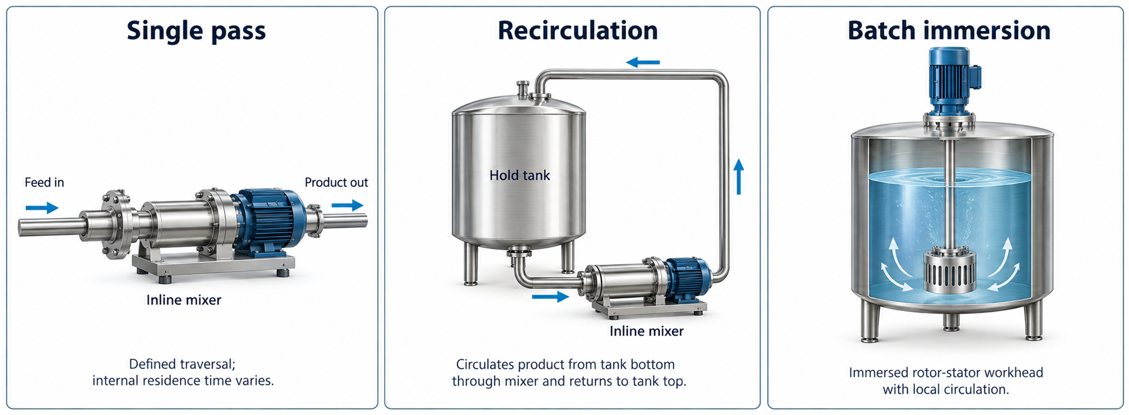
Figure 3.1. Single-pass, recirculating, and immersed batch arrangements. [1].
For an active volume Vₐ and volumetric flow rate Q, the nominal residence time is
where tₐ is the nominal residence time in the active zone and Q is the volumetric flow rate.
For a recirculating tank of volume Vₜ, the mean equivalent number of passes over a processing time t is estimated as
where nₚ is the mean equivalent number of passes, Q is recirculation flow rate, t is processing time, and Vₜ is tank volume.
Interpretation of the Number of Passes
Equation (3.2) defines an engineering average. It assumes ideal tank mixing and does not imply that every fluid element completes exactly nₚ passes. Real installations exhibit residence time distributions, bypass flows, and repeated short circulation loops. Sampling must therefore demonstrate that stable product quality has been achieved.
The mean pass count must not be interpreted as a guaranteed minimum. In an additional idealized model in which a perfectly mixed tank feeds a constant flow circuit and individual passages are statistically independent, approximately 36.8% of the material remains unprocessed after one mean pass, while about 0.67% remains unprocessed after five mean passes. These are ideal probabilities, not measured properties of an actual mixer. Bypass flow and poorly exchanged regions can substantially increase the underprocessed fraction.
The final product should therefore be assessed using samples representative of the entire vessel, rather than solely the recirculation outlet. Time, flow rate, and mean pass count remain useful metrics, but must be interpreted alongside particle or droplet size distributions, rheology, or formulation-specific dissolution criteria.
Table 3.1. Comparison of batch and inline operation
| Criterion | Immersion batch mode | Inline mode |
|---|---|---|
| Material exposure | Statistical; determined by tank circulation and processing time. | All discharged material traverses the housing, but local residence time has a distribution. |
| Suitable duties | Flexible formulation, variable batch size, staged addition, and direct powder loading. | Continuous manufacturing, metered feed, single-pass treatment, and sealed processing. |
| Pumping requirements | The head must supply local suction and bulk exchange; auxiliary agitation may be required. | The rotor may pump liquid, but an external pump is often required to control flow or backpressure. |
| Heat removal | Jacketed vessel, internal coil, or external recirculation loop. | Direct integration of heat exchangers upstream or downstream of the mixer. |
| Scale up considerations | Turnover time, head position, vessel geometry, local intensity, and accumulated energy dose. | Tip speed, stage geometry, residence time in the active zone, capacity, pressure, and energy per unit volume. |
| Main risks | Air entrainment, stagnant regions, unequal exposure, and poor powder induction. | Seal loading, excessive pressure loss, blockage, heating, and insufficient treatment per pass. |