
Technical publication
Back to publications
Industrial applications
Design and Operating Principles of Rotor-Stator Mixers
okozyuk.com
Published
Read complete publication for whole-document Find and printing. Browser Find and native printing on this reader include only loaded content.
2. Principal Components and Kinematics
A batch installation generally comprises a drive, shaft, supports or bearings, immersed mixing head, and vessel. Adequate immersion depth is needed to prevent continuous gas entrainment, while appropriate clearance from the tank floor and walls is needed to establish circulation. A head that produces intense local deformation does not necessarily mix the entire tank effectively. Additional propellers, anchor agitators, or wall scrapers may be needed in large vessels, at increasing viscosity, or when ingredients are introduced nonuniformly [9, 10, 11].
In an inline installation, the working assembly is enclosed in a sealed housing connected to a controlled inlet and outlet circuit. The rotor may develop hydraulic head, but this does not make the mixer a positive displacement pump. Depending on its geometry, imposed flow rate, and downstream resistance, the measured pressure difference may represent either a pressure rise or a pressure loss. Experimental analysis must distinguish energy dissipated within the liquid from useful hydraulic power and mechanical losses [2, 3].
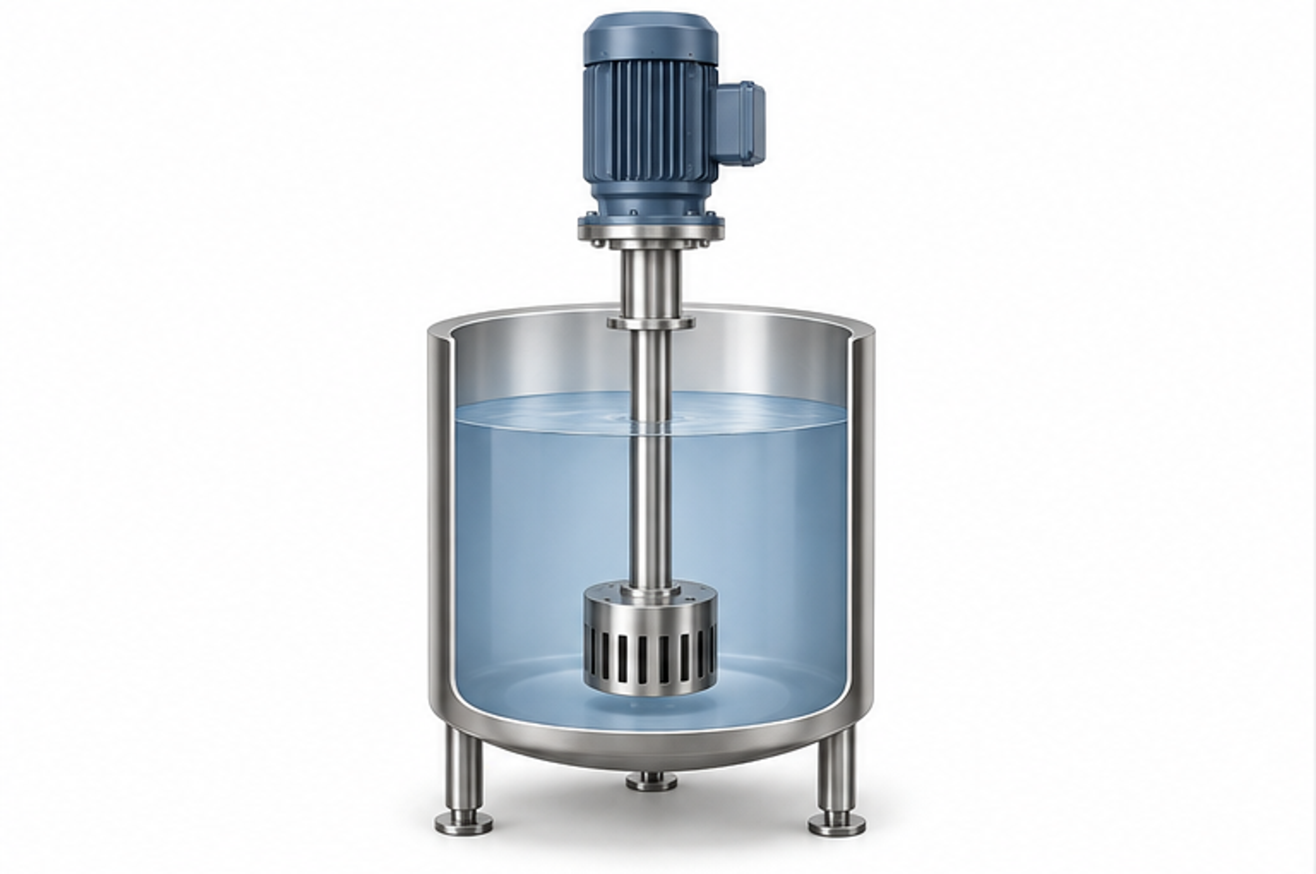
Figure 2.1. Immersed mixing head in a batch vessel. Simplified original illustration of the general arrangement. [1].
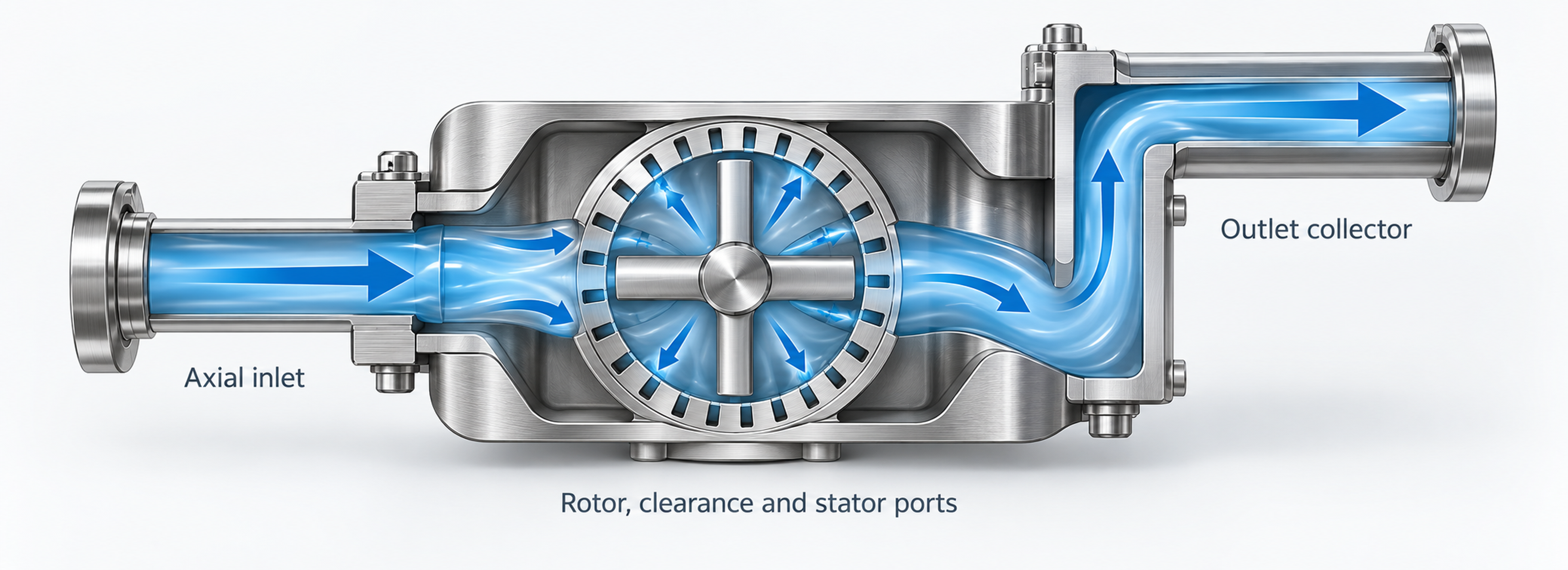
Figure 2.2. Flow path through an enclosed rotor-stator mixer: axial entry, transport across a radial working region, and discharge collection. Original explanatory diagram [1].
2.1 Rotational Speed and Geometric Characteristics
The performance of a rotor-stator mixer depends on the combined effects of operating conditions, particularly rotational speed, and the principal geometric parameters of the working pair. Changing any of these variables changes the overall hydrodynamic flow structure.
Rotational frequency N is expressed in revolutions per second, whereas n is expressed in revolutions per minute. Angular velocity is defined by
where ω is angular velocity in rad/s and N is rotational frequency in s⁻¹.
The outside diameter D of the rotor determines its circumferential or tip speed, given by
where Uₜ is rotor tip speed, D is rotor diameter, N is rotational frequency in revolutions per second, and n is rotational speed in revolutions per minute.
Tip speed is more useful than rotational speed alone when comparing rotors of different diameters. Nevertheless, it is only a kinematic measure: equal tip speeds do not imply equal gap shear rates, aperture velocities, pumping performance, or energy dissipation. Actual working geometry must therefore be considered. The permissible speed for a particular machine must be obtained from the manufacturer; the kinematic curves presented here do not define a safe operating envelope [2, 3].
When z identical, uniformly spaced rotor elements pass a fixed point, their fundamental passage frequency is
where fₚ is the element passage frequency; z is the number of repeating rotor blades, teeth, holes, or cavities; N is revolutions per second; and n is revolutions per minute.
Equation (2.3) gives the fundamental passage frequency at a fixed location, not the full interaction spectrum for rotors and stators with different numbers of elements. Additional spectral components arise from relative spatial phase, nonuniform pitch, shaft speed modulation, and channel geometry. The pressure fluctuation spectrum should therefore be measured when designing equipment for pulsating action.