
Technical publication
Back to publications
Reactors & equipment
Cavitation in Hydraulic Machinery, Valves, Piping, and Marine Systems
okozyuk.com
Published
Read complete publication for whole-document Find and printing. Browser Find and native printing on this reader include only loaded content.
3 Cavitation in Valves and Piping Systems
3.1 Vena Contracta and Pressure Recovery
When a liquid accelerates through a throttling element, the jet continues to contract downstream of the minimum geometric area. Static pressure reaches a minimum near the vena contracta and then partially recovers as the jet expands and mixes. Cavitation begins when the local minimum pressure falls below vapor pressure and the resulting cavities subsequently enter a region of higher pressure. Consequently, a trim with strong pressure recovery can cavitate even when the measured upstream and downstream pipe pressures remain above vapor pressure [6,7,8].
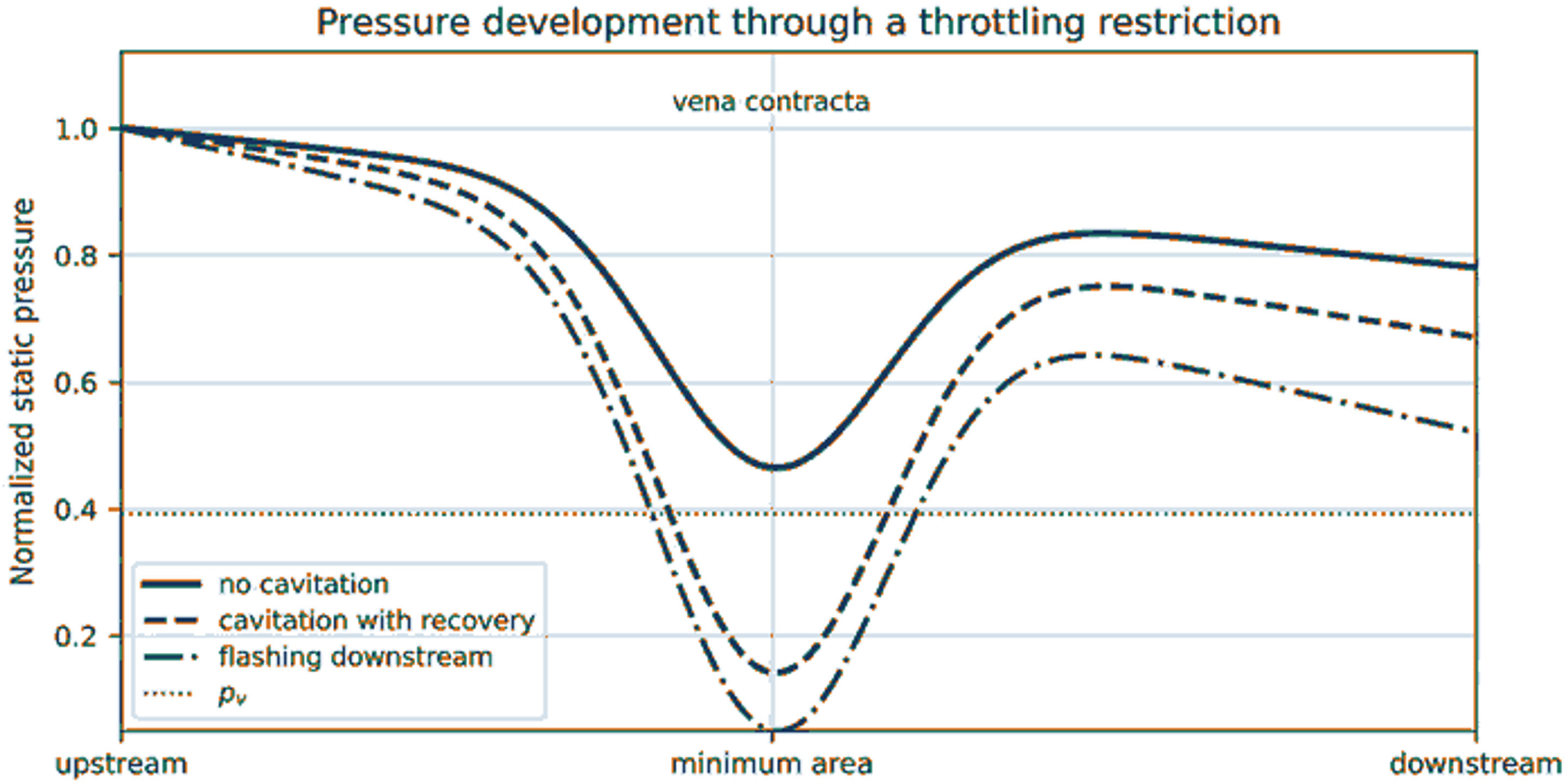
Figure 4. Pressure profiles through a throttling restriction. Cavitation requires pressure recovery above vapor pressure, whereas flashing persists when downstream pressure remains below vapor pressure [6,7,8].
3.2 Cavitation Indices and Recovery Factor
A commonly used valve cavitation index, sigma_v, is defined by Eq. (6), where p_1 is the upstream pressure and p_2 is the downstream pressure. Index conventions differ among industries, and some definitions use an inverse ratio or a different pressure reference. Published inception, constant cavitation, or damage thresholds must therefore be applied only with the matching definition, valve style, size, travel, and test method [6,7,8].
The liquid pressure recovery factor F_L is defined by Eq. (7), where p_vc is the pressure at the vena contracta. A smaller recovery factor indicates a larger difference between the minimum internal pressure and the measured downstream pressure. Valve sizing methods combine pressure recovery with the critical pressure ratio to predict liquid choking. Final selection should follow a recognized sizing standard and manufacturer data [6,7].
3.3 Cavitation, Choking, and Flashing
Table 2. Pressure states in valves and restrictions [2].
| State | Pressure relationship | Downstream behavior | Primary risk |
|---|---|---|---|
| Single phase liquid | Minimum pressure remains above vapor pressure. | No vapor generated by pressure reduction. | Turbulence, vibration, or erosion may still occur for other reasons. |
| Incipient cavitation | Small regions intermittently fall below vapor pressure. | Cavities collapse after pressure recovery. | High frequency noise; little performance change; possible early pitting. |
| Developed cavitation | A substantial vapor region forms near the vena contracta. | Repeated collapse in trim, body, or downstream pipe. | Noise, vibration, erosion, and reduced capacity. |
| Choked cavitating flow | Increasing pressure drop no longer produces the expected increase in liquid flow. | Vapor volume controls effective flow area. | Capacity limitation and severe dynamic loading. |
| Flashing | Downstream pressure remains at or below vapor pressure. | Two phase mixture persists downstream. | High velocity erosion, vibration, and large volume expansion; collapse may occur farther away if pressure later rises. |
3.4 Piping Locations and Control Measures
Cavitation may also develop at orifices, reducers, partially open isolation valves, strainers, pump bypasses, sudden contractions, separated elbows, nozzles, and high velocity branch connections. The most vulnerable surface may lie downstream of the restriction because cavity collapse occurs along the recovering jet. A modification that merely relocates the pressure minimum can therefore transfer damage rather than eliminate it [4,6,7,8].
Stage the pressure drop. Use multiple restrictions or multistage trim so that each local pressure reduction remains below a damaging level and the total dissipation is distributed.
Use tortuous path or multiorifice trim. Multiple small jets reduce the energy of each individual jet and can relocate collapse into a protected region, but passage dimensions must remain compatible with solids loading and fouling.
Increase downstream pressure. A backpressure valve or process modification can raise the local pressure profile, provided that the added restriction does not create a new cavitating location.
Increase valve size or change valve style. Reduced velocity and a valve geometry with lower pressure recovery can reduce cavitation severity, but an oversized control valve may exhibit poor controllability and unstable operation at low travel.
Protect the downstream pipe. Increase downstream pipe size, use a diffuser where appropriate, provide adequate straight length, avoid closely coupled elbows, and select resistant materials when residual cavitation cannot be eliminated.
Distinguish flashing. Anti cavitation trim cannot condense vapor when downstream thermodynamic conditions require a persistent two phase state. Flashing service therefore requires erosion resistant geometry and appropriate downstream sizing.