
Technical publication
Back to publications
Reactors & equipment
Cavitation in Hydraulic Machinery, Valves, Piping, and Marine Systems
okozyuk.com
Published
Read complete publication for whole-document Find and printing. Browser Find and native printing on this reader include only loaded content.
2 Cavitation in Pumps and Impellers
2.1 Locations and Mechanisms
In a centrifugal pump, shaft work is converted into fluid head by the rotating impeller and the stationary casing or diffuser. Cavitation most commonly develops at the impeller eye and blade leading edge, where high relative velocity produces a local pressure minimum. Additional cavitating structures may arise in tip leakage vortices, balance passages, wear ring clearances, inlet and discharge recirculation zones, blade wake interactions, and diffuser or volute regions. Because each mechanism responds differently to operating point and geometry, diagnosis and mitigation must be mechanism specific [1,2].
Table 1. Pump cavitation locations and characteristic signatures [1].
| Location or mechanism | Common operating condition | Typical evidence | Priority response |
|---|---|---|---|
| Impeller eye and leading edge | Insufficient suction head, high temperature, excessive speed, high flow, or inlet prewhirl. | Vapor at blade inlet, crackling noise, head loss as severity increases. | Increase suction pressure, reduce losses or speed, correct inlet geometry. |
| Inlet recirculation | Operation well below best efficiency flow. | Intermittent low frequency pressure fluctuations, vapor near inlet and suction pipe. | Move operating point, use minimum flow control, review impeller and suction design. |
| Discharge recirculation | Very low flow and high internal recirculation. | Noise and erosion near blade discharge or cutwater, heat rise. | Avoid prolonged low flow, provide bypass, revise impeller or casing geometry. |
| Tip or clearance vortex | Open impeller, inducer, axial machine, or large clearance. | Vortex core vapor and localized erosion away from the nominal leading edge. | Reduce clearance, weaken vortex, relocate collapse, improve surface resistance. |
| Diffuser or volute interaction | Off design incidence or strong blade wake. | Pressure pulsation at blade passing frequency and local vapor pockets. | Correct operating point, vane geometry, spacing, or cutwater clearance. |
| Internal seals and balance devices | High pressure drop through small clearance. | Pitting, unstable axial thrust, leakage change. | Stage pressure drop, change clearance geometry, raise local backpressure. |
2.2 Net Positive Suction Head
Net positive suction head available (NPSHA) is the total absolute suction head at the pump datum in excess of the liquid vapor pressure head. For a specified suction reference section and for an open suction vessel, two commonly used forms are given by Eqs. (1) and (2), respectively.
In these expressions, p_s is the absolute suction pressure, V_s is the suction velocity, p_surface is the absolute pressure above the liquid surface, z_s is the static elevation of that surface relative to the pump datum, h_f,s is the suction line loss, p_v is the saturation vapor pressure, rho is liquid density, and g is gravitational acceleration. Sign conventions must be applied consistently. NPSHA varies with flow rate, liquid level, vessel pressure, temperature, fouling, valve position, and transient acceleration [1,3].
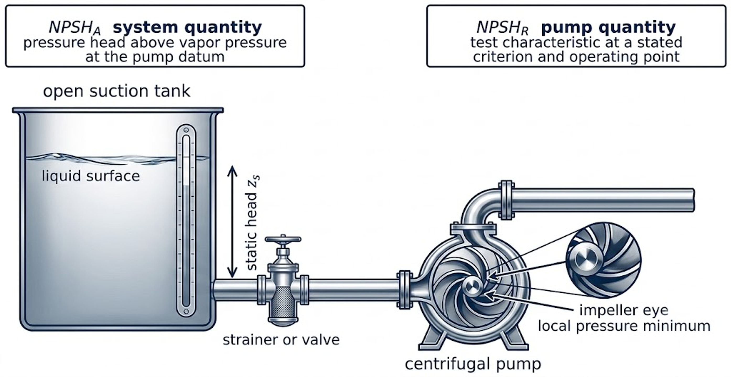
Figure 1. Pump suction system and NPSH concepts [2].
Net positive suction head required (NPSHR) is a pump characteristic established by test at a specified speed, flow rate, liquid, and acceptance criterion. NPSH3 commonly denotes the NPSH at which total pump head has decreased by 3 percent relative to a noncavitating reference. Cavitation inception generally precedes this test point, and acoustic emission or erosion may occur at higher NPSH values. Manufacturer curves should therefore be interpreted together with the applicable test definition and the consequences of cavitation in the intended service [1,3].
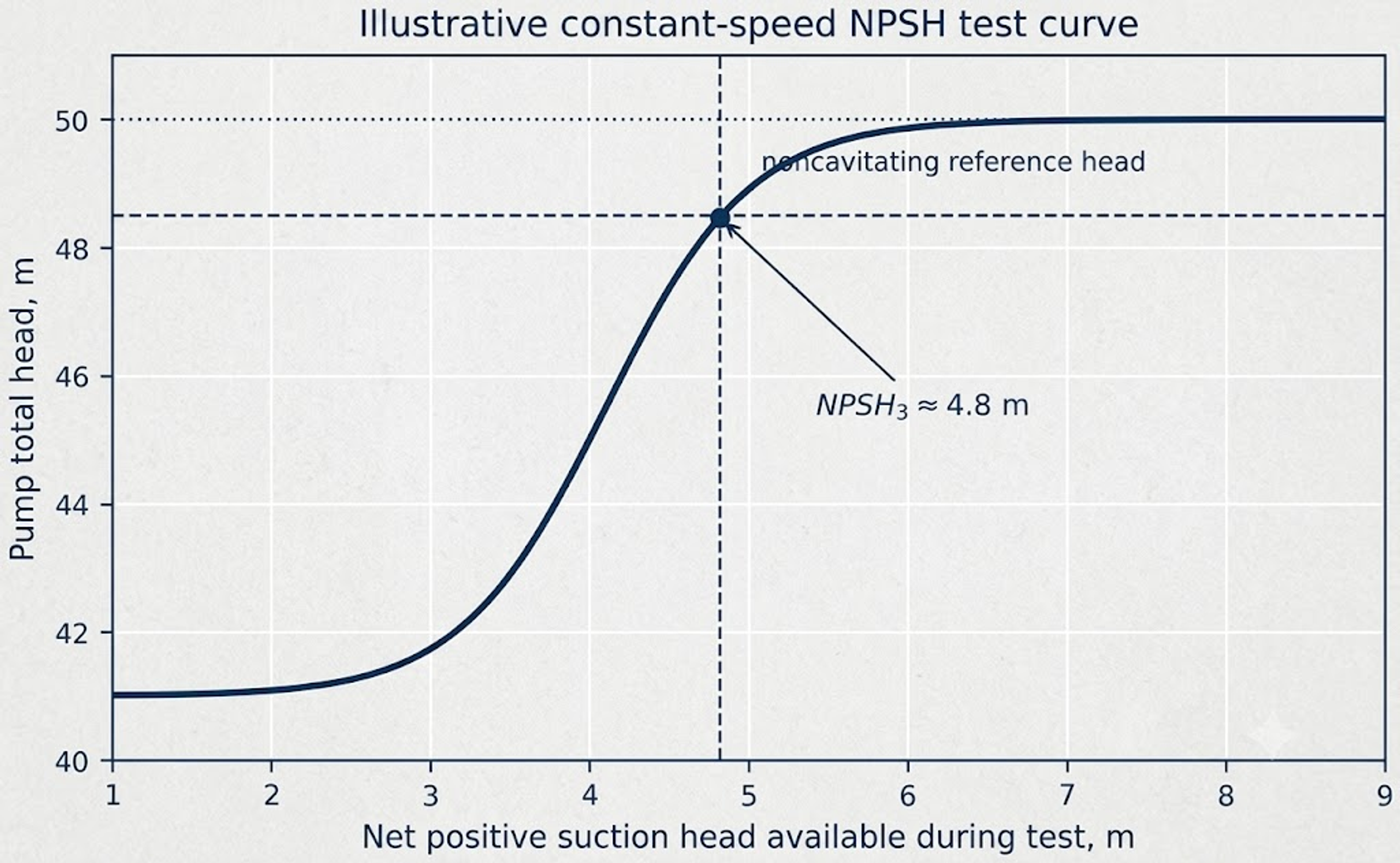
Figure 2. Illustrative NPSH3 test curve. The 3 percent head drop criterion is a repeatable pump test point, not a universal inception or damage threshold [1,3].
Two simple measures are used to express NPSH margin: the absolute margin M and the margin ratio M_R, as defined by Eq. (3). The required margin is application specific because pump type, speed, energy density, operating region, liquid properties, duty criticality, and acceptable performance degradation differ among services. A single percentage margin is therefore not universally applicable [1].
Suction specific speed is a comparative indicator defined by Eq. (4), where n is rotational speed and Q is flow rate under a stated unit convention. Its numerical value depends on the selected units and pump definition, so the convention must be declared whenever the parameter is reported. A high suction specific speed may indicate aggressive inlet loading and a narrower stable low flow range, but it is not an independent criterion for cavitation [1].
Hydraulic power and pump efficiency are related by Eq. (5).
A reduction in developed head, unstable power demand, loss of efficiency, or flow limitation can provide indirect evidence of developed cavitation. At inception, however, acoustic and pressure signatures may appear before a measurable change in efficiency.
2.3 Damage Patterns and Operational Symptoms
Pump cavitation is often associated with crackling or gravel like noise, but sound alone is not diagnostic because entrained gas, bearing defects, solids, and recirculation can produce similar signatures. A more reliable diagnosis combines the operating state, performance trends, pressure or vibration data, and physical inspection. Cavitation erosion near the impeller inlet typically appears as rough, scalloped pitting and may progress to loss of blade profile, imbalance, crack initiation, and leakage [1,4].
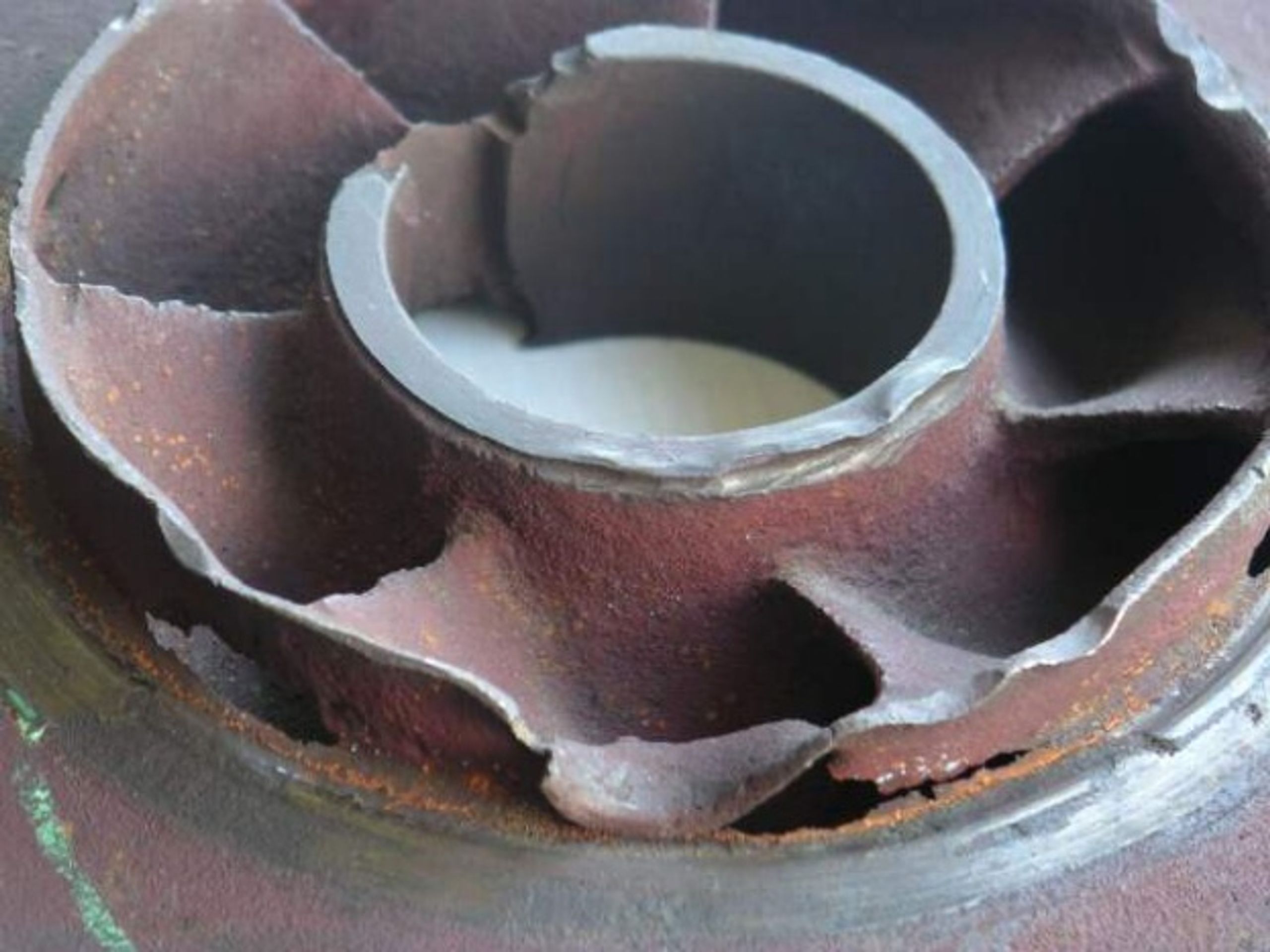
Figure 3. Cavitation damage on a centrifugal pump impeller. Photograph by Jean Jacques Milan [5].
2.4 Prevention Priorities for Pumps
Pump evaluation should begin with consistent measurements of absolute suction pressure, liquid temperature, vapor pressure, liquid level, and flow rate. Use of relative pressure without the appropriate barometric correction can produce an incorrect NPSHA value.
-
Reduce suction line losses by increasing pipe diameter where justified, shortening the suction run, opening or removing restrictive fittings, cleaning strainers, and eliminating gas pockets. Provide the straight approach flow required by the pump inlet design.
-
Increase the available suction head by raising liquid level or vessel pressure, lowering the pump elevation, reducing liquid temperature when the process permits, or using a booster pump or inducer.
-
Reduce rotational speed or shift operation toward the preferred operating region when feasible. Suction side throttling should not be used as the routine method of flow control.
-
Evaluate inlet recirculation and discharge recirculation independently of low NPSH cavitation. A large NPSH margin does not correct an unstable off design internal flow pattern.
-
After a hydraulic or mechanical modification, verify the result using pressure and performance data together with vibration or acoustic trends and inspection. Sound alone is insufficient for confirmation.