
Technical publication
Back to publications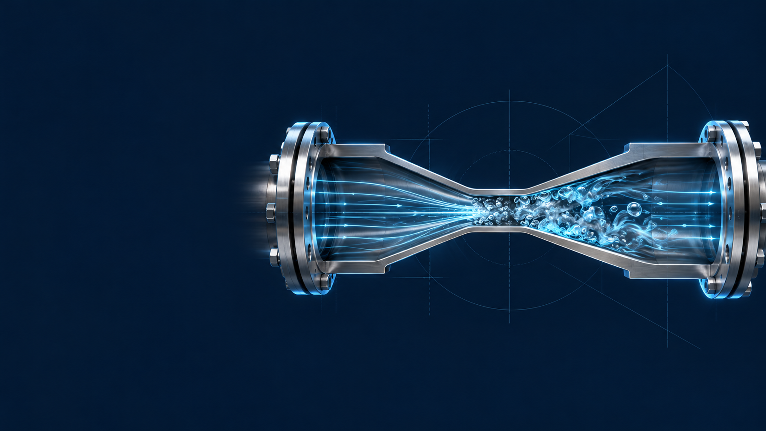
Reactors & equipment
Calculations of Hydrodynamic Cavitation Devices
okozyuk.com
Published
Read complete publication for whole-document Find and printing. Browser Find and native printing on this reader include only loaded content.
8 Conclusions
Hydrodynamic cavitation device design requires a hierarchy of models. Continuity, energy balance, dimensionless groups, and calibrated coefficients provide transparent preliminary sizing and establish flow area, velocity, pressure drop, power, residence time, and mechanical demand. These calculations do not independently predict cavity cloud structure, collapse distribution, process conversion, or service life.
For static flow through devices, total open area is only the initial geometric parameter. Hole number, thickness, edge condition, ligament, downstream chamber geometry, pressure tap location, and recovery behavior determine the active pressure history. Venturi calculations must include throat length and diffuser recovery in addition to throat diameter. Multistage devices require stage by stage pressure accounting rather than an assumed equal loss distribution.
For vortex devices, radial equilibrium explains how tangential velocity produces a low pressure core, but the free vortex model must be limited by a finite core and replaced by a two phase model once the calculated pressure reaches vapor pressure. Circulation, core radius, outlet geometry, aspect ratio, and device scale require calibration. Parallel scale out can preserve a validated core structure more reliably than simple geometric enlargement.
For dynamic devices, tip speed, rotational Reynolds number, rotor cavitation number, flow coefficient, power number, clearance ratio, and feature passage frequency form a coupled similarity set. Because power is strongly dependent on speed and diameter, a calibrated power number should not be transferred to a new geometry or flow regime without verification. Rotor stress, fatigue, thermal growth, balance, vibration, seals, and wear are integral design variables.
Structural material selection should separate pressure containment from cavitation wear. A durable design intentionally locates collapse, provides replaceable inserts or liners, preserves cleanable geometry, and establishes inspection and contamination limits. ASTM G32 and coating studies support comparative screening, but plant service life must be established by representative flow testing and pilot inspection. Final pressure vessel and piping design must comply with the applicable codes.
A validated design is therefore an operating envelope supported by measured flow, absolute pressure, power, temperature, cavity signature, product response, and equipment condition. Cavitation number is one coordinate within that envelope rather than a complete design criterion.