
Technical publication
Back to publications
Reactors & equipment
Anti-Cavitation Control Valves
okozyuk.com
Published
Read complete publication for whole-document Find and printing. Browser Find and native printing on this reader include only loaded content.
Abstract
Cavitation in liquid control valves results from local pressure reduction below vapor pressure followed by vapor collapse during pressure recovery. The associated microjets, pressure waves, vibration, and unsteady hydraulic forces can cause trim erosion, pressure boundary damage, noise, loss of control authority, and reduced service life. This article presents a unified engineering treatment of cavitation physics, liquid valve sizing parameters, pressure recovery behavior, and anti-cavitation trim architecture. The discussion relates cavitation indices and liquid choking criteria to practical design strategies, including staged pressure reduction, opposed jet bubble isolation, stacked disk and concentric sleeve trims, axial multistage geometries, multipath trims, dirty service configurations, and fixed energy dissipators. Material selection, seat protection, outlet velocity, actuator stability, solids tolerance, and system layout are examined as coupled design variables. Application considerations are summarized for water distribution, power generation, oil and gas, petrochemical, and low flow injection services. A worked sizing example demonstrates preliminary severity assessment, choked flow capacity, stage count estimation, and hydraulic power dissipation. The article also reviews field diagnosis, maintenance, computational fluid dynamics, patent development, topology optimization, and additive manufacturing. Final valve selection should be based on the complete operating envelope and tested coefficients for the specific valve and trim geometry. Keywords: cavitation; control valves; anti-cavitation trim; pressure staging; liquid choking; valve sizing; severe service.
6. Materials and Mechanical Design
6.1 Hydraulic Design First, Material Hardness Second
Hardening alone does not eliminate cavitation; it only delays material loss while collapse energy remains. Durable severe-service valves combine a hydraulic pressure profile that limits cavity intensity with materials capable of resisting the remaining mechanical and chemical attack. Martensitic stainless steels, precipitation-hardened stainless steels, cobalt-chromium hardfacing, nickel-chromium-boron alloys, and tungsten carbide are among the materials used for severe trim. [1-3, 6-10, 12, 15]
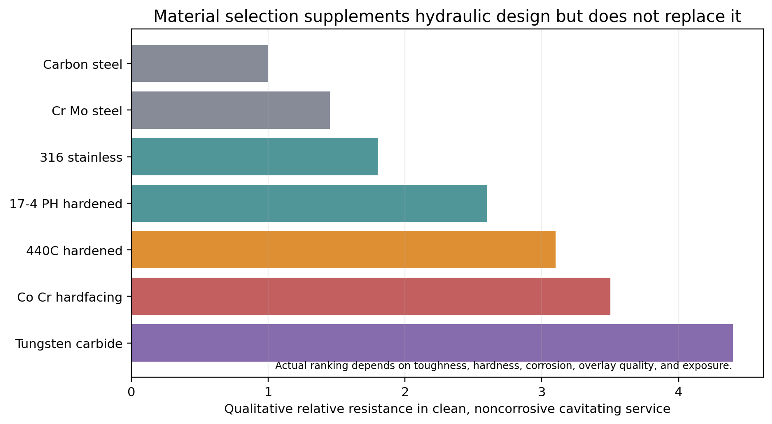
Figure 32. Qualitative material resistance comparison.
The qualitative ranking in Figure 32 is not a procurement specification. Toughness, yield strength, fracture strain, hardness, corrosion resistance, overlay dilution, porosity, residual stress, joining method, and thermal cycling can all affect performance. In corrosive liquids, corrosion resistance may be more important than hardness because repeated cavitation impacts remove protective passive films. [3, 15]
6.2 Material Property Relations
SAMSON summarizes experimental work correlating cavitation resistance with deformation energy to fracture. A simplified proportionality is
where is the energy absorbed per unit volume before fracture. This explains why hardness alone does not fully predict cavitation resistance. A brittle very hard material can crack under repeated impact, while a tougher material may absorb more energy. [3]
6.3 Plug, Stem, Cage, and Seat Stability
High-pressure liquid forces can excite lateral plug motion and stem vibration. Severe-service valves therefore use long guiding surfaces, large stems, robust plug-to-stem connections, rigid cage stacks, and actuators with adequate stiffness and thrust margin. Misalignment increases local clearance, creates asymmetric jets, and accelerates erosion. [9, 10, 15]
Pressure-balanced plugs reduce actuator force but introduce balance seals and leakage paths that must tolerate temperature, particulate, and cycling. Unbalanced trims simplify sealing but require greater actuator force. Flow-to-open operation is often preferred for dynamic stability and seat protection, although the correct flow direction depends on body geometry and the required location of the pressure-recovery region. [1, 2, 7, 9, 10]
6.4 Shutoff and Leakage Class
The specified leakage class must be compatible with service temperature and pressure differential. Metal seats are common in high-temperature and abrasive service. Protected soft seats can provide tight shutoff at moderate temperature when a metal collar shields the polymer from direct flow. Pressure-reduction stages should not use the final shutoff edge as the principal throttling surface. [5, 7, 9, 10, 15]
6.5 Corrosion, Flashing, and Mixed Damage
Cavitation erosion, solid-particle erosion, corrosion, and flashing can occur simultaneously. Mixed damage changes surface morphology and can invalidate material selection based solely on clean-water testing. In flashing service, vapor persists downstream and the dominant damage mechanism may become high-velocity two-phase erosion rather than bubble collapse. Expanded outlets, angle bodies, hard materials, and downstream pipe protection may therefore be required. [1, 3, 13, 15]