
Technical publication
Back to publications
Anti-Cavitation Control Valves
okozyuk.com
Published
Abstract
Cavitation in liquid control valves results from local pressure reduction below vapor pressure followed by vapor collapse during pressure recovery. The associated microjets, pressure waves, vibration, and unsteady hydraulic forces can cause trim erosion, pressure boundary damage, noise, loss of control authority, and reduced service life. This article presents a unified engineering treatment of cavitation physics, liquid valve sizing parameters, pressure recovery behavior, and anti-cavitation trim architecture. The discussion relates cavitation indices and liquid choking criteria to practical design strategies, including staged pressure reduction, opposed jet bubble isolation, stacked disk and concentric sleeve trims, axial multistage geometries, multipath trims, dirty service configurations, and fixed energy dissipators. Material selection, seat protection, outlet velocity, actuator stability, solids tolerance, and system layout are examined as coupled design variables. Application considerations are summarized for water distribution, power generation, oil and gas, petrochemical, and low flow injection services. A worked sizing example demonstrates preliminary severity assessment, choked flow capacity, stage count estimation, and hydraulic power dissipation. The article also reviews field diagnosis, maintenance, computational fluid dynamics, patent development, topology optimization, and additive manufacturing. Final valve selection should be based on the complete operating envelope and tested coefficients for the specific valve and trim geometry. Keywords: cavitation; control valves; anti-cavitation trim; pressure staging; liquid choking; valve sizing; severe service.
Anti-Cavitation Control Valves
Fundamentals, Sizing, Trim Architectures, Applications, and Diagnostics
Oleg Kozyuk, Ph.D.
Abstract
Cavitation in liquid control valves results from local pressure reduction below vapor pressure followed by vapor collapse during pressure recovery. The associated microjets, pressure waves, vibration, and unsteady hydraulic forces can cause trim erosion, pressure boundary damage, noise, loss of control authority, and reduced service life. This article presents a unified engineering treatment of cavitation physics, liquid valve sizing parameters, pressure recovery behavior, and anti-cavitation trim architecture. The discussion relates cavitation indices and liquid choking criteria to practical design strategies, including staged pressure reduction, opposed jet bubble isolation, stacked disk and concentric sleeve trims, axial multistage geometries, multipath trims, dirty service configurations, and fixed energy dissipators. Material selection, seat protection, outlet velocity, actuator stability, solids tolerance, and system layout are examined as coupled design variables. Application considerations are summarized for water distribution, power generation, oil and gas, petrochemical, and low flow injection services. A worked sizing example demonstrates preliminary severity assessment, choked flow capacity, stage count estimation, and hydraulic power dissipation. The article also reviews field diagnosis, maintenance, computational fluid dynamics, patent development, topology optimization, and additive manufacturing. Final valve selection should be based on the complete operating envelope and tested coefficients for the specific valve and trim geometry. Keywords: cavitation; control valves; anti-cavitation trim; pressure staging; liquid choking; valve sizing; severe service.
1. Introduction
Control valves regulate process variables by converting fluid pressure into irreversible hydraulic losses. In liquid service, the associated acceleration can reduce local static pressure below the liquid vapor pressure. Vapor cavities then form in high-velocity regions and collapse as pressure recovers. The resulting microjets, shock waves, unsteady forces, noise, and vibration can erode valve trim, damage the pressure boundary, loosen instrumentation, and reduce usable valve capacity. Cavitation is therefore both a fluid-dynamic phenomenon and a reliability concern. [1-3, 13-15, 21]
Anti-cavitation valve design follows two principal strategies. Cavitation elimination divides the total pressure loss among sufficient stages to keep local static pressure above the relevant vapor pressure throughout the trim. Cavitation control accepts limited vapor formation but directs bubble collapse toward the liquid core and away from metal surfaces. Selection between these strategies depends on pressure ratio, absolute pressure, flow range, fluid vapor pressure, fluid cleanliness, particle size, shutoff requirements, allowable noise, valve size, and exposure duration. [1, 2, 4, 5, 11, 14, 15]
No single trim geometry is optimal for every service condition. Small drilled passages provide high hydraulic resistance in a compact volume but are susceptible to plugging. Larger tortuous passages tolerate debris but require greater trim volume. Radial disk stacks distribute flow circumferentially, whereas axial trims can keep all pressure-reduction stages active throughout the stroke. Opposed jets can protect surfaces under mild cavitation, while severe pressure ratios generally require multistage designs. Valve selection should therefore match the hydraulic mechanism to the complete process envelope rather than infer suitability from line size alone. [2, 5, 9-12, 14, 15]
1.1 Scope of the Article
This article addresses liquid control valves and related fixed energy dissipators used for pressure reduction, flow control, pump recirculation, spray water, injection, distribution systems, reservoir filling, continuous relief, and high-pressure liquid letdown. Gas-noise trim is discussed only where the same geometric mechanisms are also applicable to liquid service. Flashing is treated separately from cavitation because vapor persists downstream and therefore requires a different mitigation strategy. [1, 2, 13-15]
The engineering relations are presented for preliminary calculation and conceptual design. Final sizing should use the applicable edition of IEC 60534 or the corresponding ISA adoption together with tested valve coefficients for the exact body, trim, flow direction, travel, and attached fittings. Relevant standards include IEC 60534-2-1 for installed flow-capacity equations, IEC 60534-2-3 for capacity test procedures, IEC 60534-8-2 for laboratory measurement of hydrodynamic noise, IEC 60534-8-4 for hydrodynamic noise prediction, and ISA-RP75.23-1995 (R2024) for evaluation of control-valve cavitation. [16-20]
1.2 Cavitation, flashing, and liquid choking
Cavitation occurs when local liquid pressure falls sufficiently to produce vapor and subsequently rises above vapor pressure, causing the vapor structures to condense. Flashing begins by the same mechanism, but the downstream pressure does not recover above vapor pressure, so vapor persists as a two-phase stream. Liquid choking occurs when vapor formation limits mass flow. After the critical condition is reached, further reduction of downstream pressure produces little or no increase in flow for a fixed upstream state and valve opening. [1-3, 13-15]
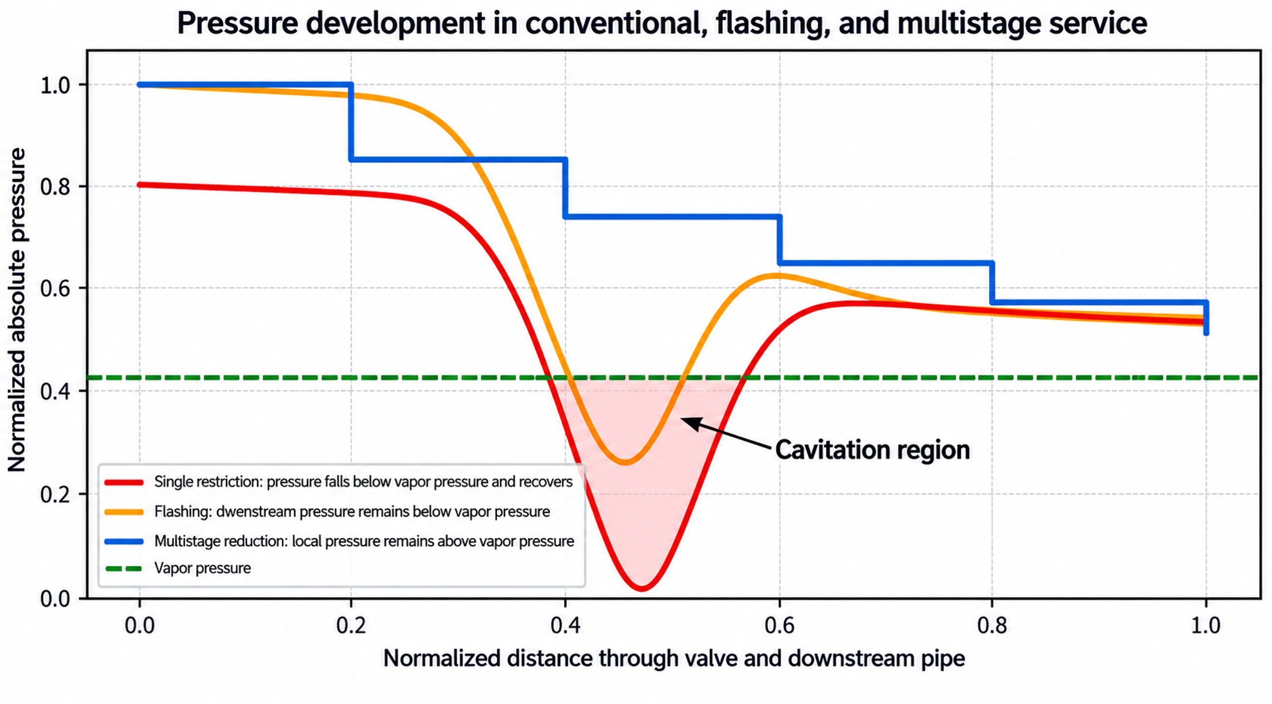
Figure 1. Comparison of conventional cavitating flow, flashing, and staged pressure reduction.
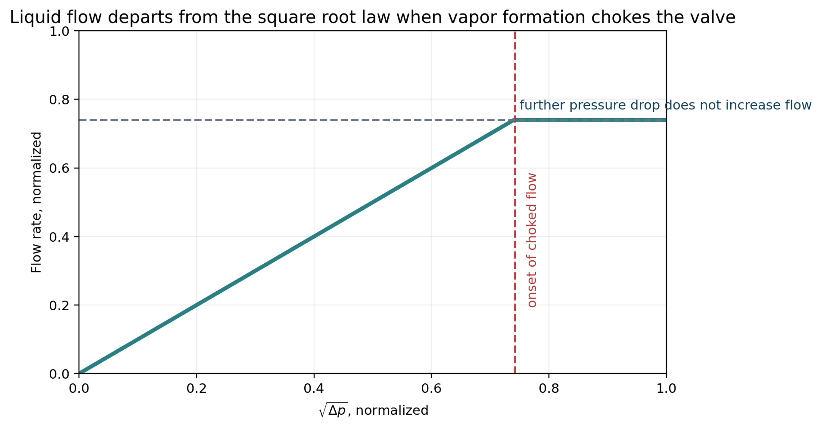
Figure 2. Idealized transition from the square root flow relation to liquid choked flow.
1.3 Consequences for the process plant
At incipient cavitation, the audible signature may begin as crackling and progress to hissing, rattling, or a gravel-like sound as the cavity field develops. These observations are useful diagnostic indicators, but airborne noise is not a direct measure of material damage. Harmful collapse can occur without exceptionally high external noise, and vibration can propagate into the actuator, positioner, tubing, pipe supports, and connected equipment. [1, 2, 10, 11, 14, 15]
Cavitation damage generally occurs downstream of the controlling restriction. Typical surfaces exhibit irregular pitting, edge loss, seat-line erosion, and, in severe cases, penetration of the pressure boundary. Repeated impact by microjets and pressure waves can remove passive oxide films and accelerate subsequent corrosion. Seat leakage is particularly damaging because a leakage jet may cavitate continuously while the valve is nominally closed. [2, 3, 13-15, 21]
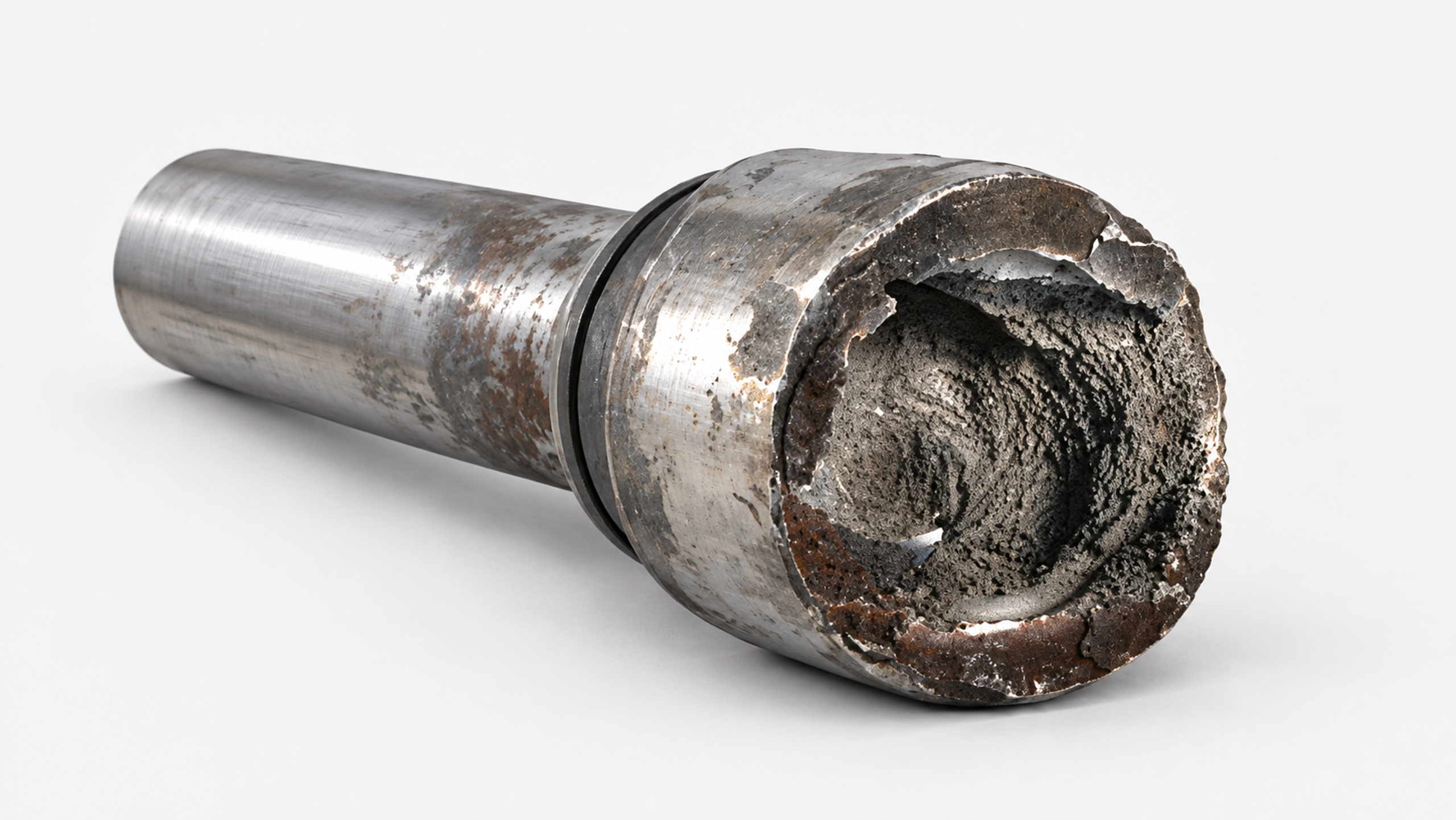
Figure 3. Cavitation damage and factors that control material loss.
2. Physical Basis of Cavitation in a Control Valve
2.1 Continuity, acceleration, and the vena contracta
For steady incompressible flow, continuity relates volumetric flow rate to local flow area and mean velocity.
As the effective flow area decreases near the throttling edge, mean velocity increases. The maximum mean velocity and minimum mean pressure occur at or near the vena contracta, typically downstream of the physical restriction. Its location depends on valve geometry, opening, flow direction, and turbulent separation. [1, 2, 13-15]
An engineering energy balance between an upstream station and a local station can be written as
The loss term includes viscous dissipation, mixing, separation, impingement, and repeated acceleration and deceleration. In a control valve, total pressure decreases monotonically, whereas static pressure can fall sharply and then recover partially. Instantaneous local pressure can be substantially lower than the mean because vortex cores and turbulent fluctuations generate localized pressure minima. Cavitation can therefore begin before a one-dimensional mean-pressure profile reaches vapor pressure. [3, 15, 22-24]
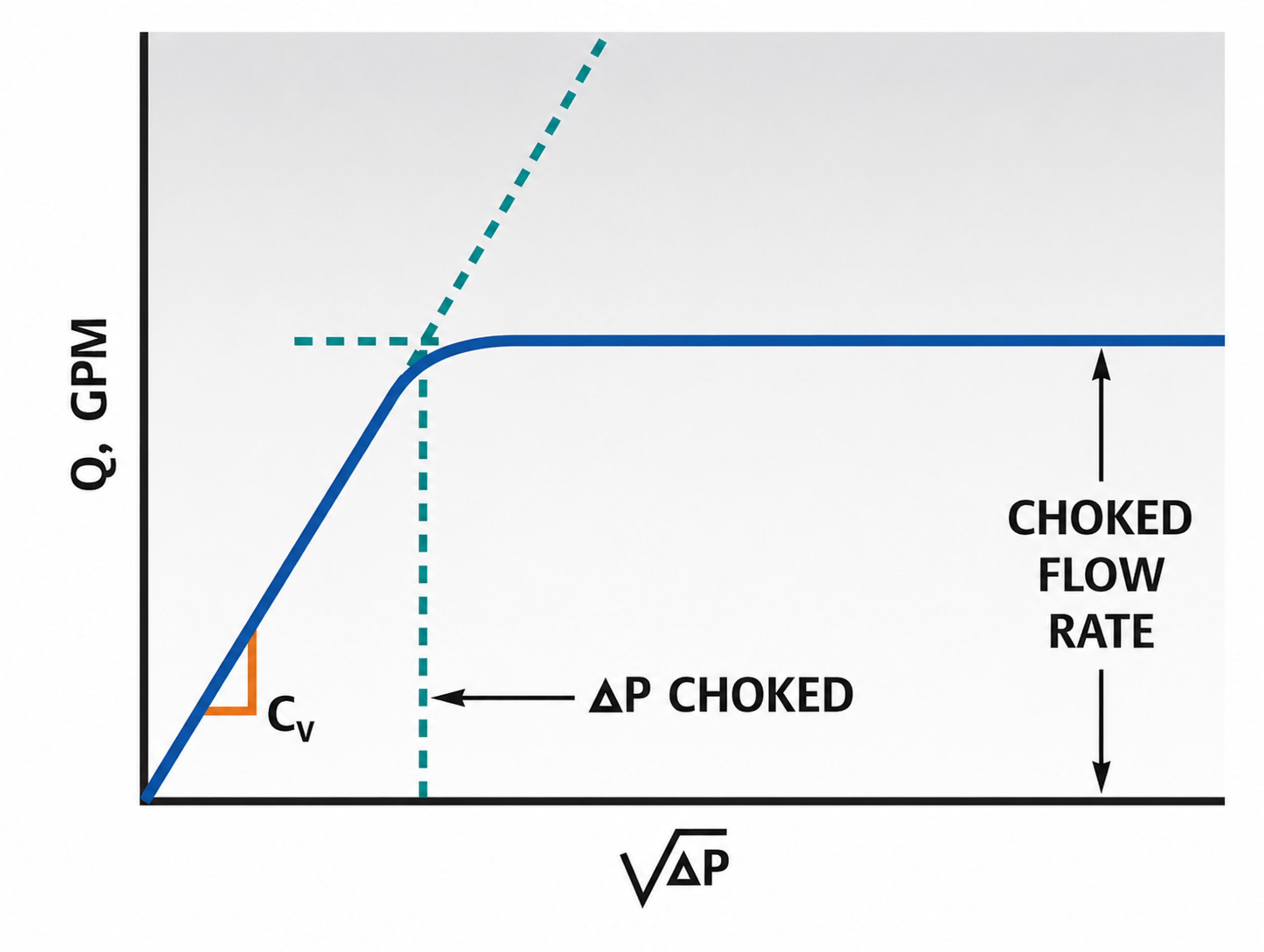
Figure 4. Choked flow behavior: flow rate versus the square root of pressure drop.
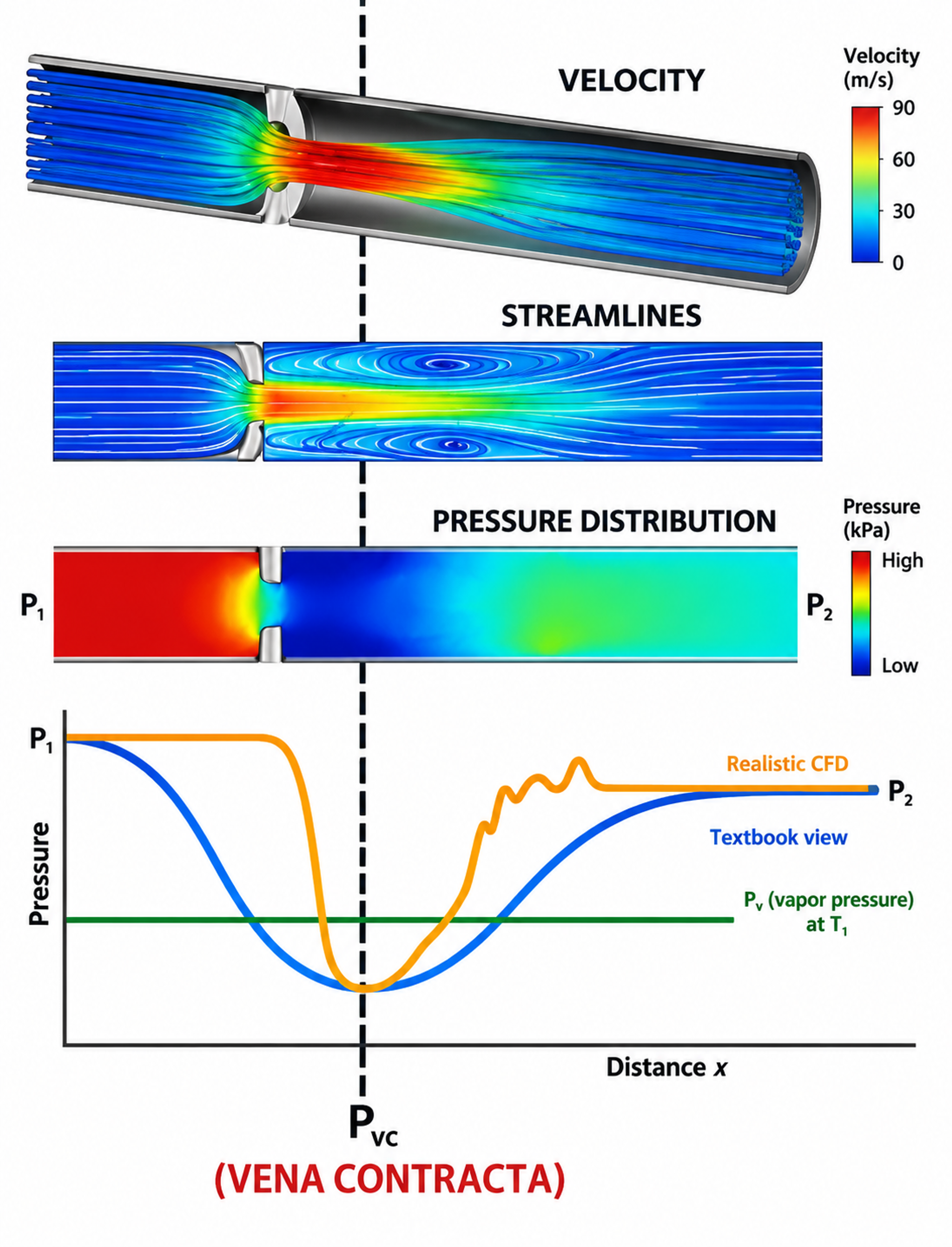
Figure 5. Mean pressure, local velocity, streamlines, and a CFD based pressure trace near a restriction.
2.2 Cavitation nuclei and incipient cavitation
A perfectly homogeneous liquid can sustain large tension, but industrial liquids contain dissolved gas, microscopic bubbles, crevices, suspended particles, and surface imperfections that act as nuclei. A spherical nucleus of radius is in mechanical equilibrium when the external pressure and surface tension balance the vapor and gas pressures inside the bubble. [3, 21]
If the enclosed gas changes approximately isothermally, a simplified gas relation is
As external pressure decreases, the bubble radius increases. Beyond a critical condition, the equilibrium becomes unstable and rapid growth begins. Incipient cavitation depends on the nuclei population, dissolved gas, temperature, surface tension, residence time, and the spectrum of pressure fluctuations. Because these variables are rarely characterized in industrial service, valve-sizing methods generally use vapor pressure and experimentally determined valve coefficients as practical reference quantities. [3, 21-24]
2.3 Bubble growth and collapse
Spherical bubble dynamics are commonly described by the Rayleigh Plesset equation. One standard form is
where represents the pressure inside the bubble. This equation shows that collapse rate increases when the surrounding pressure rises above the internal pressure. It also shows the roles of inertia, surface tension, and viscosity. For an empty spherical cavity collapsing under a constant pressure difference, the classical Rayleigh estimate is
Near a solid boundary, final bubble collapse is generally asymmetric. A pressure gradient across the bubble can drive a liquid microjet through the cavity toward the wall. Microjet impact and the associated pressure wave generate high local stress over a small area and short duration. Repeated impacts can initiate plastic deformation, fatigue, cracking, and progressive material removal. [3, 15, 21]
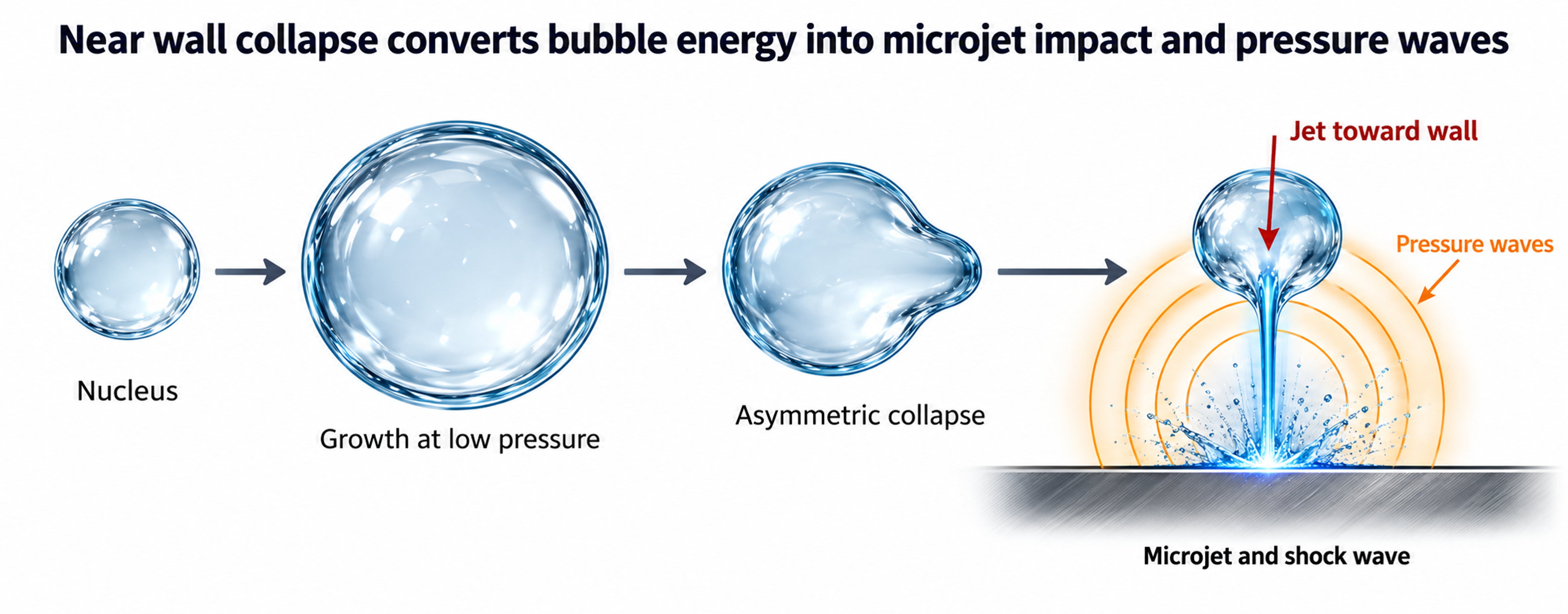
Figure 5. Stages of near-wall bubble growth and collapse.
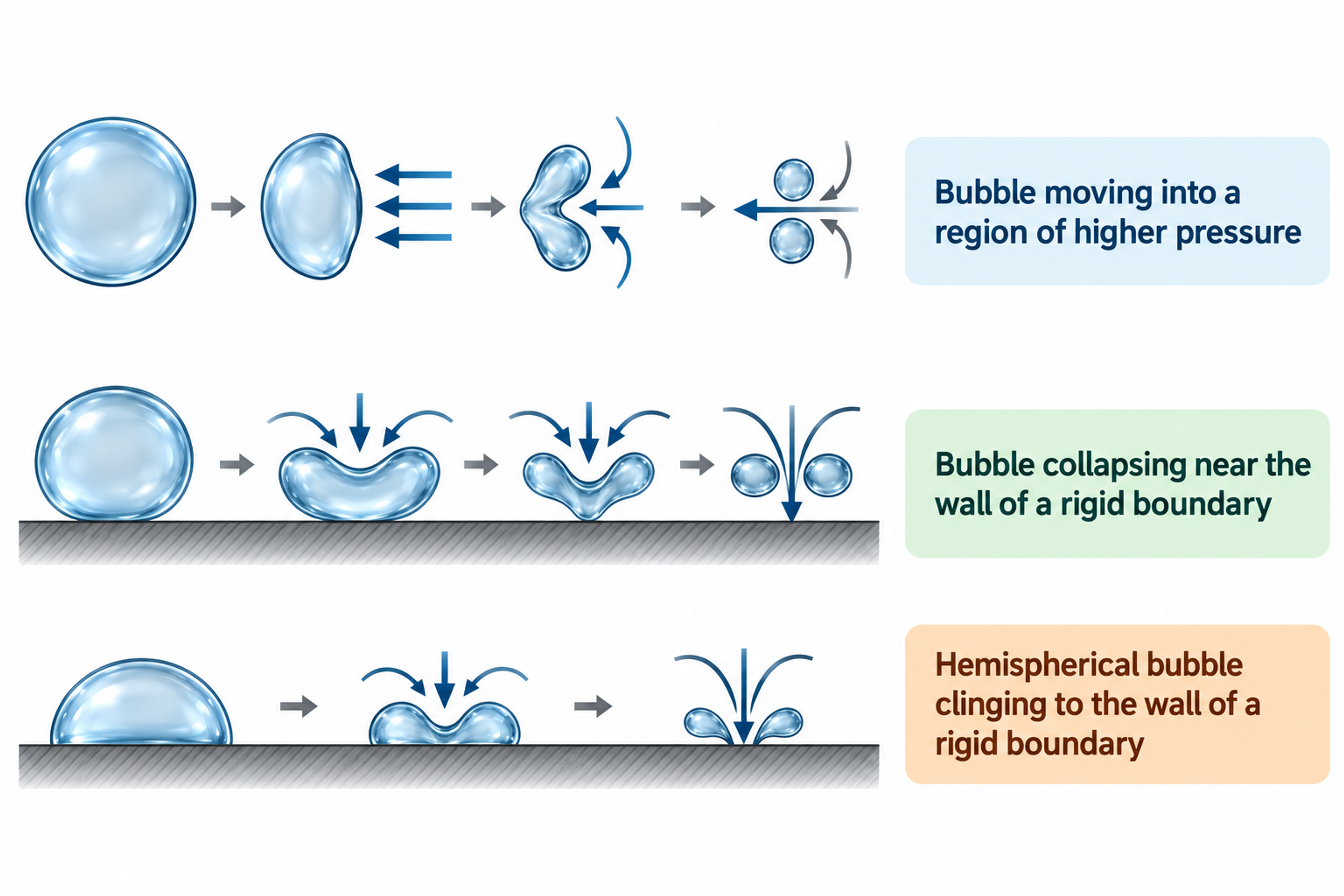
Figure 6. Bubble collapse near free and solid boundaries, with the associated jet velocity relation.
2.4 Cavitation zone, residence time, and damage location
The cavity field is a distributed, time-dependent structure rather than a single bubble at a fixed location. Vapor structures form in shear layers and vortex cores, convect downstream, grow while local pressure remains low, and collapse as pressure recovery intensifies. The highest damage rate often occurs near the downstream end of the visible cavity region, where a fraction of bubbles collapse sufficiently close to a solid surface to transfer high impact energy. [3, 15, 21]
The location of bubble collapse is therefore an important design variable. Opposed jets and perforated plugs can move the collapse region toward the liquid core. Staged trims can suppress vapor formation by limiting the pressure drop imposed by each stage. Expanded outlet bodies and larger valve galleries increase separation between the cavity field and the pressure boundary, while protected seats keep the highest-velocity region away from shutoff surfaces. [1, 2, 9-12, 14, 15]
2.5 Noise, vibration, and unsteady force
Each bubble-collapse event generates a broadband pressure pulse. A developed cavity field contains many such events, with a spectrum governed by bubble size, pressure ratio, valve opening, trim geometry, pipe transmission, and the acoustic response of the system. As the cavity region expands, cavitation noise often shifts toward lower frequencies, while structural vibration can excite stems, plugs, cages, actuators, and pipe supports. [3, 10, 15, 20]
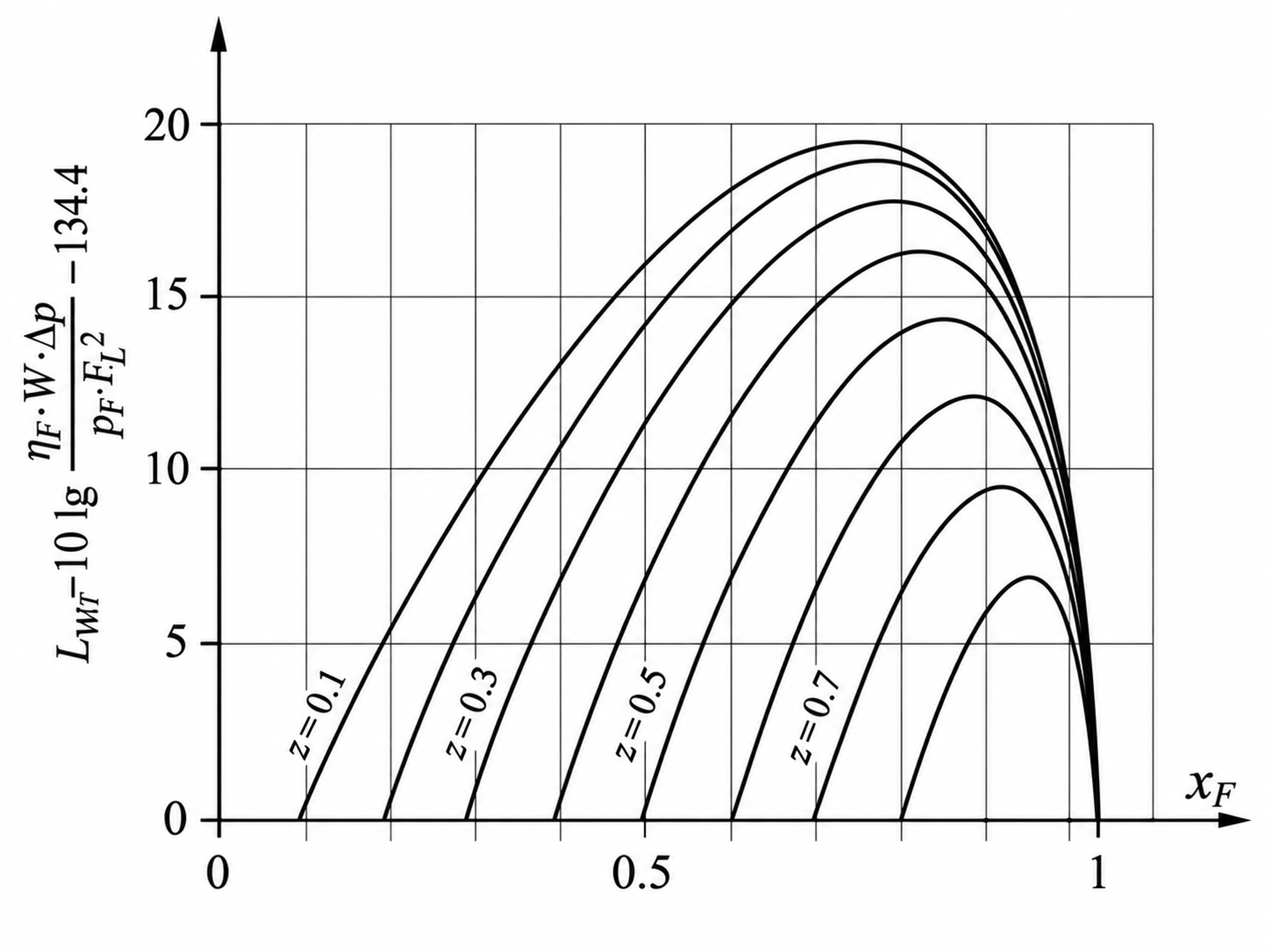
Figure 7. Sound power for standard valves with a parabolic plug (ΔLF = 0).
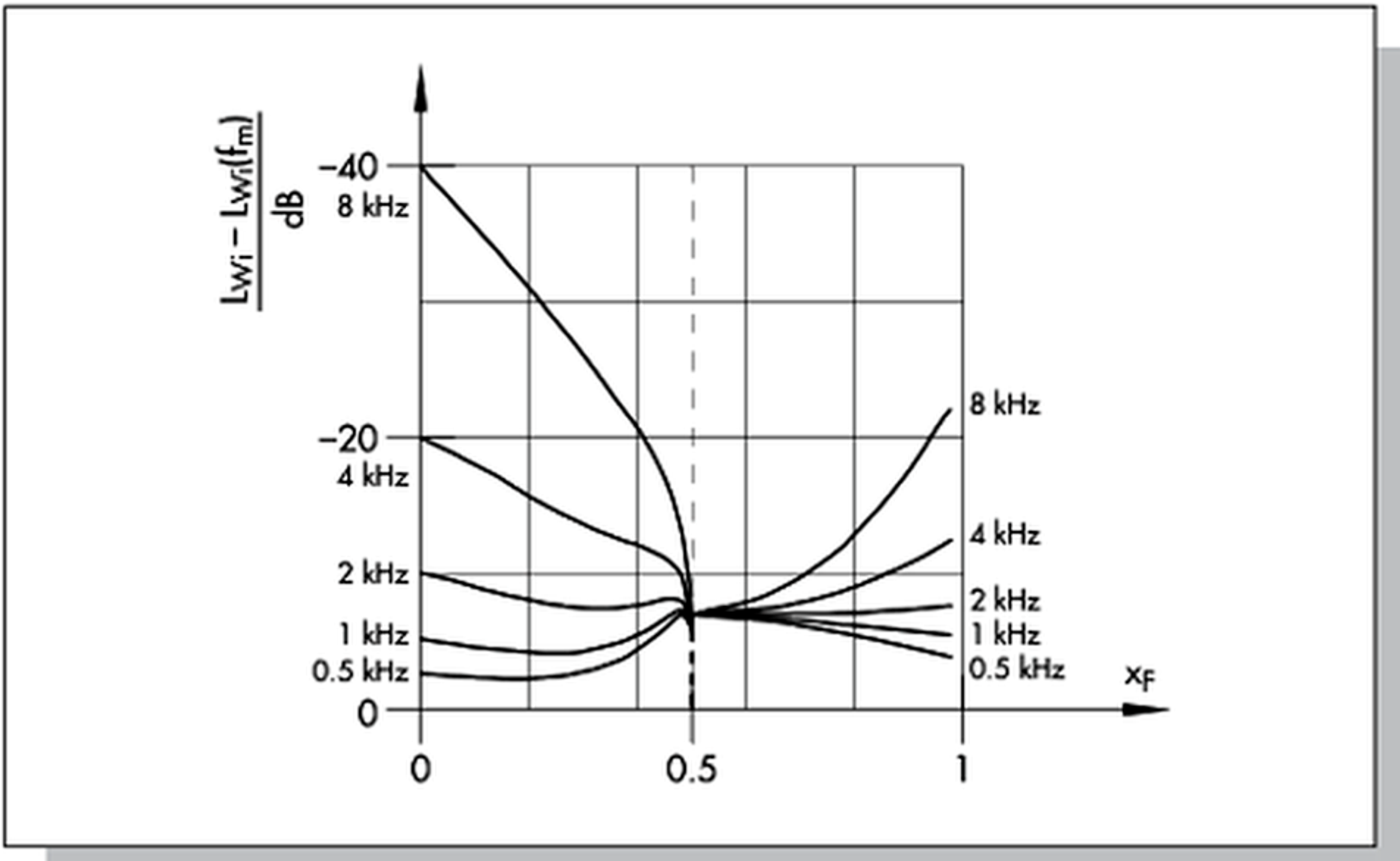
Figure 8. Measured sound-power spectrum.
IEC 60534-8-2 specifies laboratory methods for measuring hydrodynamic noise and identifying the characteristic noise increase associated with cavitation onset. IEC 60534-8-4 provides a method for predicting liquid-flow noise from normal turbulence and cavitation. Field diagnosis should combine acoustic observations with process conditions, valve position, vibration, and inspection because damaging cavitation does not necessarily coincide with the highest airborne noise level. [19, 20]
3. Cavitation Indices and Valve Sizing
3.1 Pressure Definitions
| Symbol | Definition | Engineering note |
|---|---|---|
| p₁ | Upstream absolute pressure | Use a representative location with a developed inlet profile. |
| p₂ | Downstream absolute pressure | Avoid substituting gauge pressure in vapor pressure relations. |
| Vapor pressure at flowing temperature | For mixtures, use a justified effective vapor pressure or vendor method. | |
| or | Minimum local pressure | Usually inferred from test coefficients rather than measured directly. |
| Δp | p₁ − p₂ | Actual valve pressure drop. |
| Thermodynamic critical pressure | Used in the liquid critical pressure ratio factor. |
Table 1. Pressure quantities used in liquid valve sizing.
3.2 Sigma Cavitation Index
A commonly used cavitation index expresses the available pressure margin above vapor pressure relative to the imposed pressure drop across the valve.
High means a relatively large pressure margin and low cavitation severity. Low means a severe pressure reduction. A value at or below unity indicates that the downstream pressure is at or below vapor pressure and flashing is expected. Manufacturer limits are developed by test for specific valve styles. They are not universal material constants and must be corrected where size and pressure scale effects are significant. [1, 2, 14, 16]
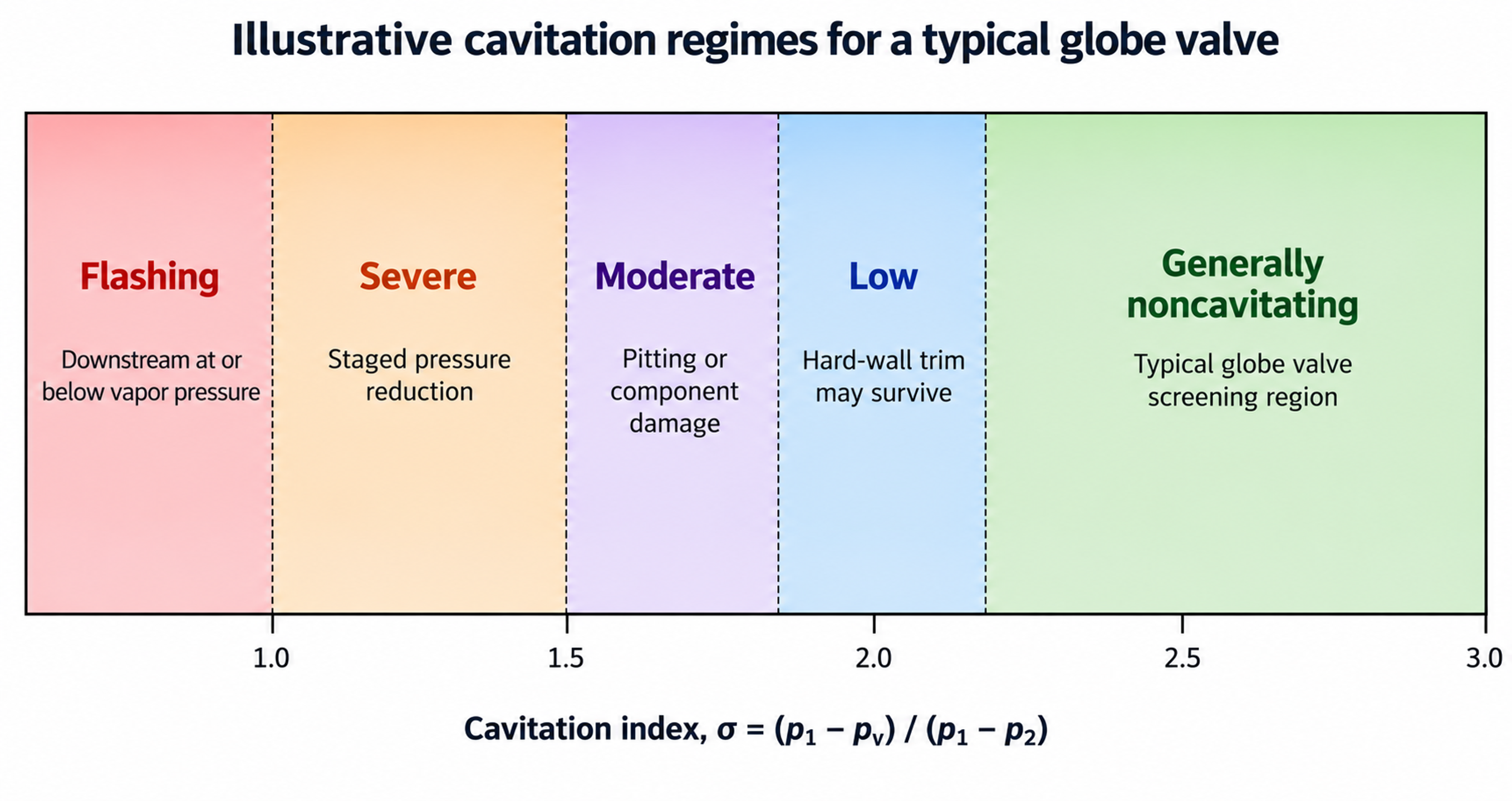
Figure 9. Illustrative regimes for a typical globe valve.
The supplied Flowserve data illustrate how a conventional globe valve can reach choked cavitation at a lower Sigma than the Sigma associated with the beginning of damage. Their example gives approximately and for a particular test valve. The same bulletin classifies staged trims such as Tiger Tooth and ChannelStream for Sigma values approaching 1.002, while opposed jet trim is intended for less severe conditions. These figures are useful for understanding relative severity but are not transferable without the manufacturer scaling procedure. [1, 2]
3.3 Operating Pressure Ratio and Incipient Cavitation Coefficient
IEC-style liquid sizing commonly uses the operating pressure ratio
which is the inverse of Sigma when the same pressure locations and absolute units are used. A valve specific incipient cavitation coefficient can be represented as
At the measured onset of cavitation, is commonly related to vapor pressure through the test method. Cavitation free operation requires the operating to remain below the applicable with an engineering margin. Because changes with travel and trim geometry, full stroke data are required for modulating service. [3, 17, 18]
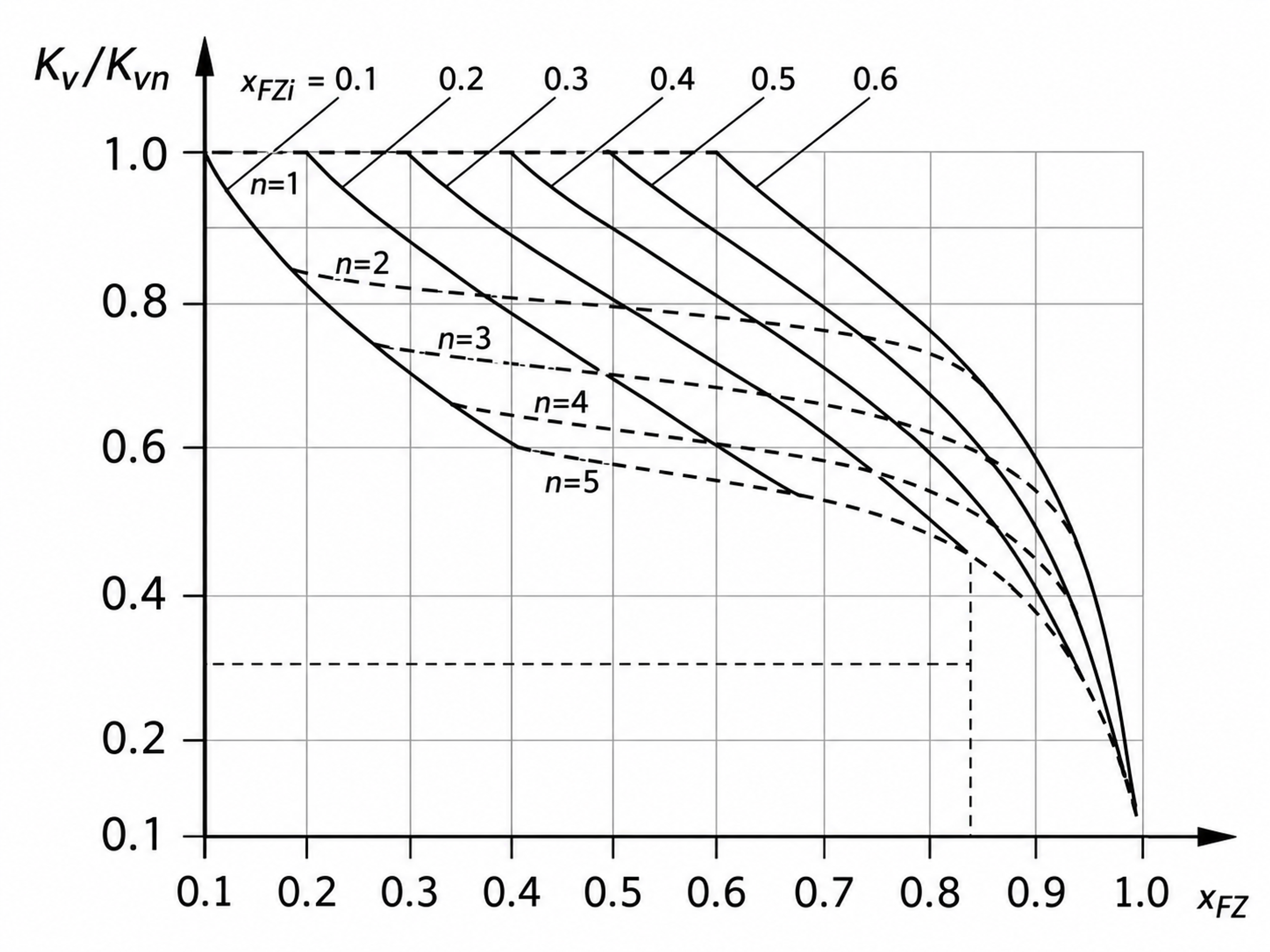
Figure 10. Relationship among multistage valve coefficient, capacity ratio, and the number of stages.
3.4 Liquid Critical Pressure Ratio Factor and Choked Pressure Drop
For preliminary liquid sizing, the liquid critical pressure ratio factor can be estimated from the vapor pressure and thermodynamic critical pressure.
For a valve without attached fittings, a commonly used choked-pressure-drop relation is
For capacity calculations, the allowable pressure drop is the smaller of the actual pressure drop and the choked pressure drop.
The liquid pressure recovery factor is determined by test and reflects valve geometry. High recovery rotary valves generally have lower and are more susceptible to cavitation at a given overall pressure drop than low recovery globe or multistage valves. Attached reducers and expanders require the combined coefficient and piping geometry factor . [13, 17, 18]
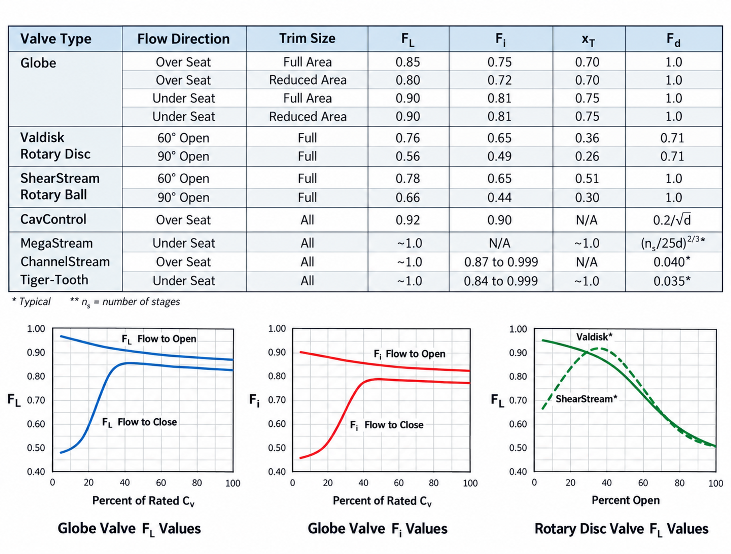
Figure 11. Typical valve pressure recovery coefficients and part travel trends, with liquid sizing relations.
3.5 Flow Coefficient
For turbulent incompressible flow in SI units, a convenient preliminary relationship is
where is in cubic meters per hour and pressure is in bar. The corresponding customary coefficient is approximately
Viscous, low-Reynolds-number, non-Newtonian, multiphase, and slurry services require additional corrections or a different flow model. A valid anti-cavitation selection must also satisfy minimum controllable flow, maximum flow, normal operating travel, rangeability, shutoff, and actuator-force requirements. [13, 17, 18]
3.6 Substantial Cavitation and Manufacturer Criteria
Some sizing systems use a liquid cavitation factor to estimate the pressure drop at which substantial cavitation begins.
The factor is specific to valve style, flow direction, and travel. It is useful for screening, but severe high-pressure service requires manufacturer assessment of absolute pressure, pressure and size scaling, material, residence time, trim-passage geometry, and the location of pressure recovery. [1, 13, 14]
3.7 Scale Effects
Laboratory cavitation data are commonly obtained with water over limited pressure and size ranges. Collapse intensity, cavity length, active-nuclei population, and exposed area can vary with valve size and absolute pressure. ISA practice and manufacturer methods therefore apply size and pressure scale corrections to a reference Sigma. A general representation is
where and are manufacturer determined scale effects. The relation is not a substitute for vendor data. It emphasizes that a favorable small-scale test coefficient cannot be applied directly to a large high pressure valve. [14, 16, 32]
4. Hydraulic Design Principles for Anti-Cavitation Trims
4.1 Divide the Pressure Drop
The most direct way to prevent vapor formation is to divide the total pressure reduction into a sequence of smaller losses. If each stage has the same individual incipient coefficient and complete pressure recovery is assumed between idealized stages, the combined coefficient is
Solving for stage count gives
These equations provide a first estimate only. Real trims exhibit incomplete interstage pressure recovery, interacting jets, variable flow area, changes in fluid velocity, and stage coefficients that vary with travel. Detailed pressure-stage allocation therefore requires tested geometry or validated computational analysis. [3, 7, 9, 10, 17, 18]
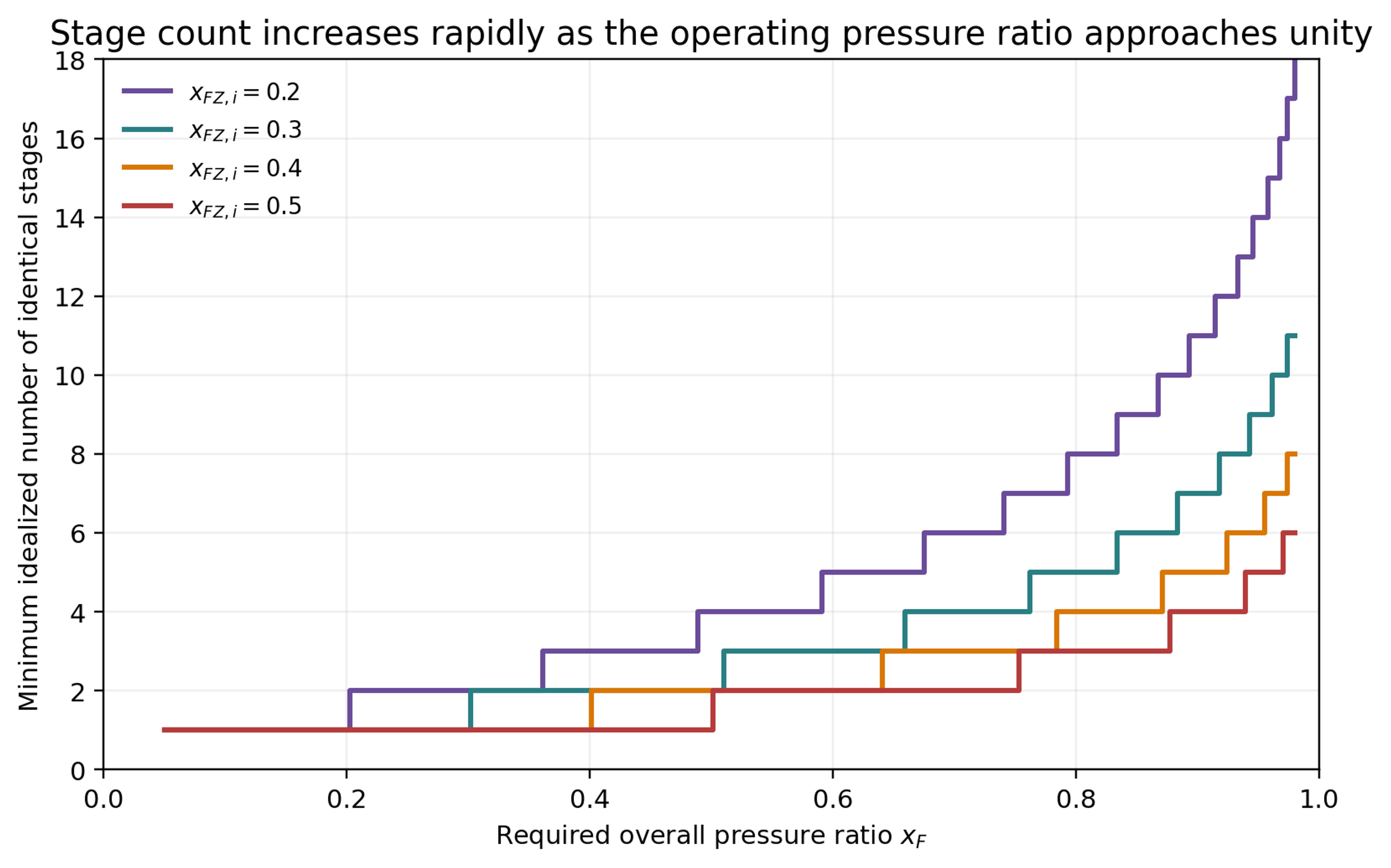
Figure 12. Idealized stage count as a function of operating pressure ratio and individual stage coefficient.
4.2 Allocate Stage Resistance to Control Velocity
Equal pressure drop per stage is not always optimal. In liquids, the pressure margin above vapor pressure decreases as static pressure falls. Later stages may therefore require smaller pressure drops, larger flow areas, or a different distribution of hydraulic resistance. Many severe-service trims use progressively expanding passages to prevent velocity from increasing downstream. Axial trims may use decreasing resistance from stage to stage, while disk stacks enlarge successive teeth or channels. [1, 2, 9, 10]
Equation (19) provides a convenient recurrence when each stage is defined by a pressure ratio relative to vapor pressure. The relationship also demonstrates the importance of absolute pressure: a pressure drop that is acceptable near the inlet can become cavitation-prone when imposed near the outlet. [3, 17, 18]
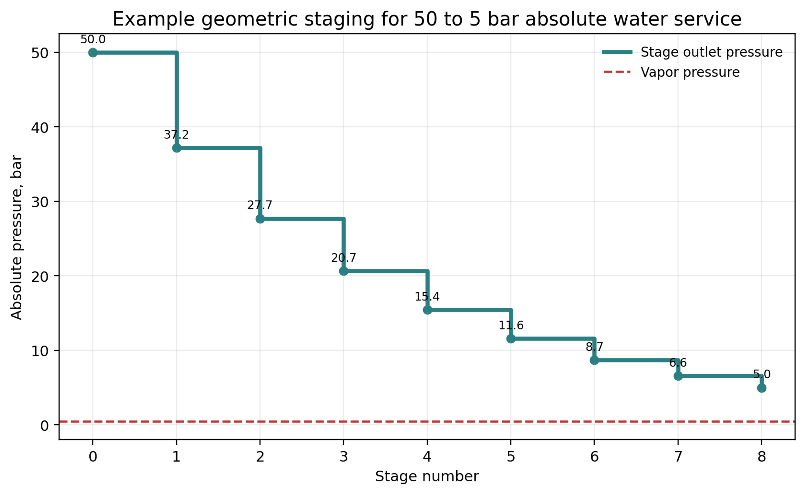
Figure 13. Geometric pressure staging for the worked example developed in Section 8.
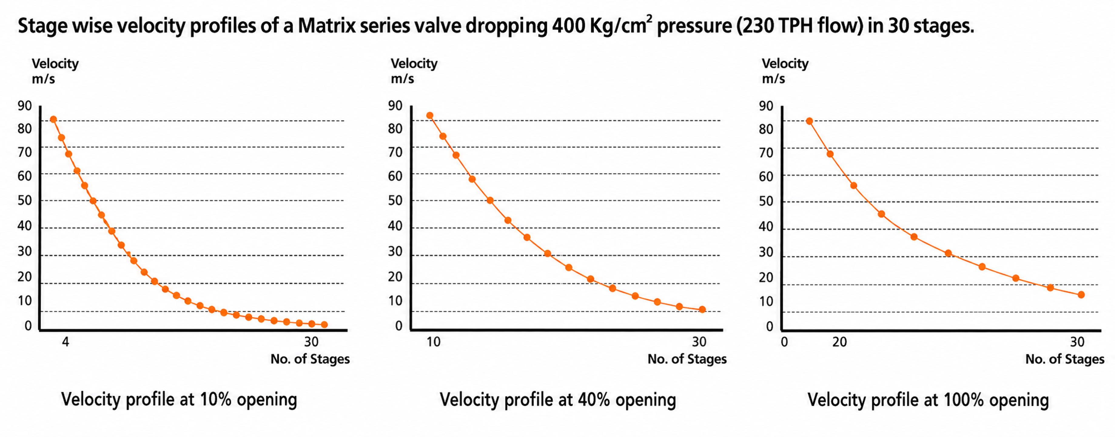
Figure 14. Stagewise velocity profiles for a thirty-stage Matrix valve at different openings.
4.3 Equivalent Capacity of Series Restrictions
For idealized incompressible restrictions in series, an equivalent coefficient can be estimated from
Increasing the number of stages reduces the capacity available from a trim of fixed nominal size. This tradeoff is fundamental. Greater cavitation resistance requires more wetted surface, longer passages, additional contractions, or greater flow subdivision, all of which consume pressure drop and trim volume. [3, 6-10, 13]
4.4 Mechanisms of Irreversible Energy Loss
Anti-cavitation trims combine sudden contraction and expansion, small-passage friction, mixing of converging streams, repeated changes in direction, surface impingement, mutual jet impingement, and controlled pressure recovery. These mechanisms convert organized kinetic energy into heat and small-scale turbulence while preventing a single dominant vena contracta from carrying the full pressure drop. [2, 14]
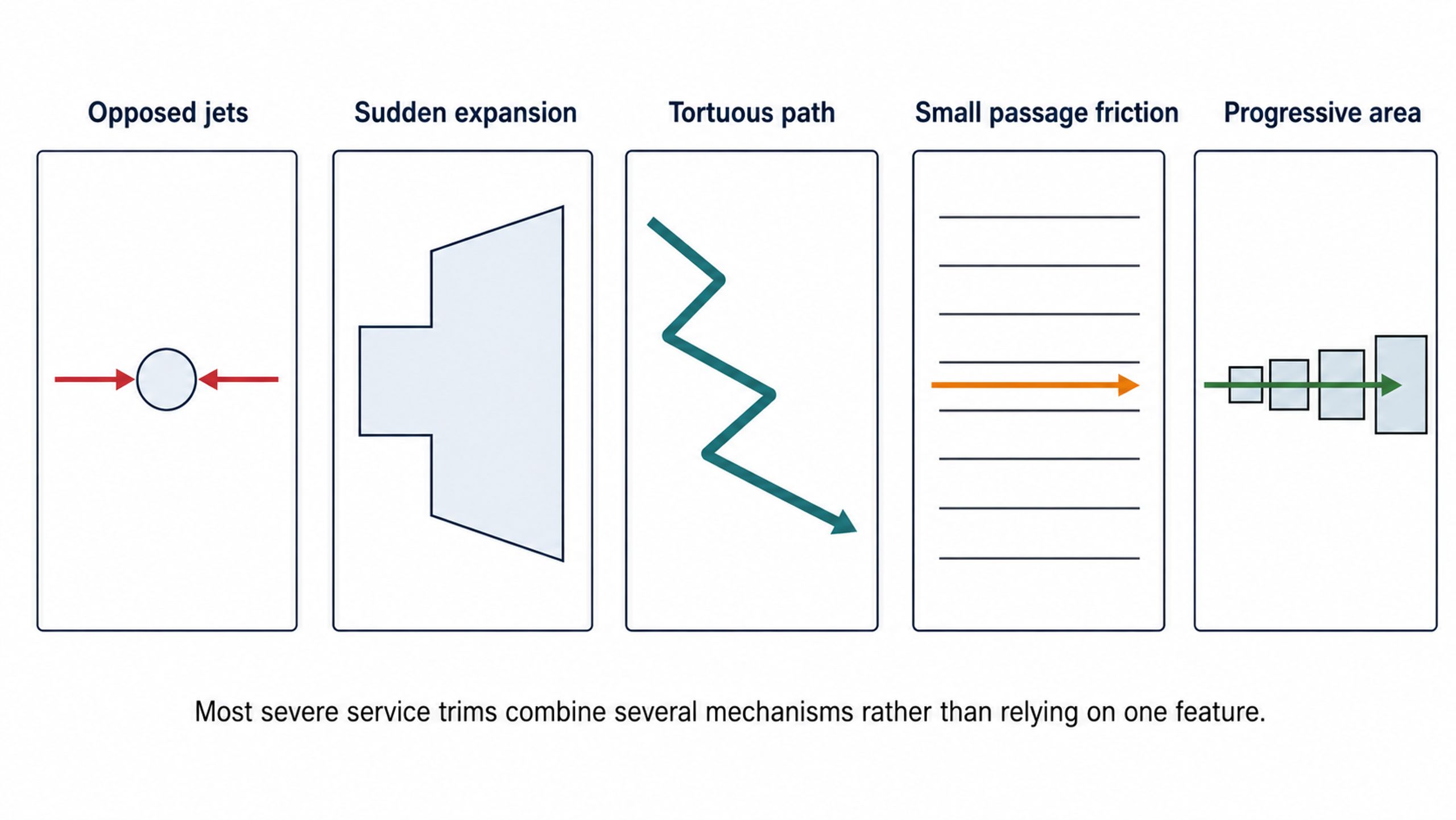
Figure 15. Principal energy dissipation mechanisms used in anti-cavitation trims.
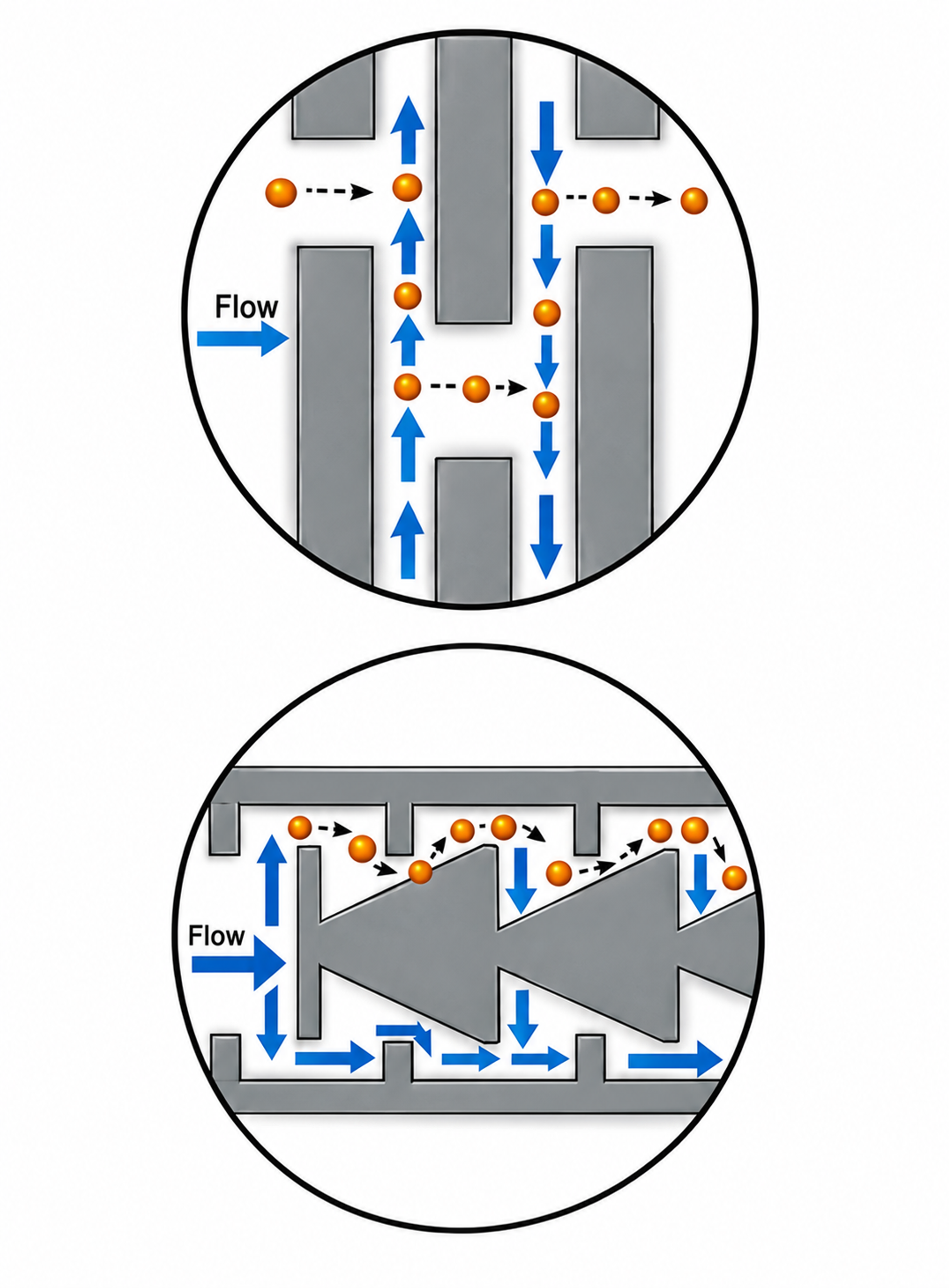
Figure 16. Examples of mechanism combinations for clean and dirty service.
4.5 Bubble Isolation by Opposed Jets
Under mild to moderate cavitation, diametrically opposed holes can direct cavitating jets toward the center of a cage. The opposing streams collide, surrounding the vapor field with liquid and promoting collapse away from the cage wall. Stepped holes are frequently used to create orifice-type behavior and move the vena contracta outside the metal passage. This mechanism is used in Flowserve CavControl, Singer dual-cage designs, Ross WaterTamer, Mascot CavFlo, and related waterworks valves. [1, 2, 4, 5, 11, 12]
Bubble isolation can control damage without eliminating vapor formation. Its capability becomes limited when the pressure drop is extremely severe, the collapse region extends beyond the protected core, or the flow field becomes asymmetric. Passage alignment, hole diameter, cage clearance, travel, and inlet distribution are therefore application-specific. [1, 2, 5, 11, 12]
4.6 Protect the Seat and Controlling Edge
Low-flow operation is often a severe condition because nearly the full pressure drop is concentrated near the seat while the opening is small. Robust designs separate shutoff from throttling. Applicable strategies include trim overlap, a sacrificial upstream seal, a plug chamber that fills before the principal stages open, tandem seats, and placement of the controlling edge downstream from the shutoff surface. [2, 6-10, 15]
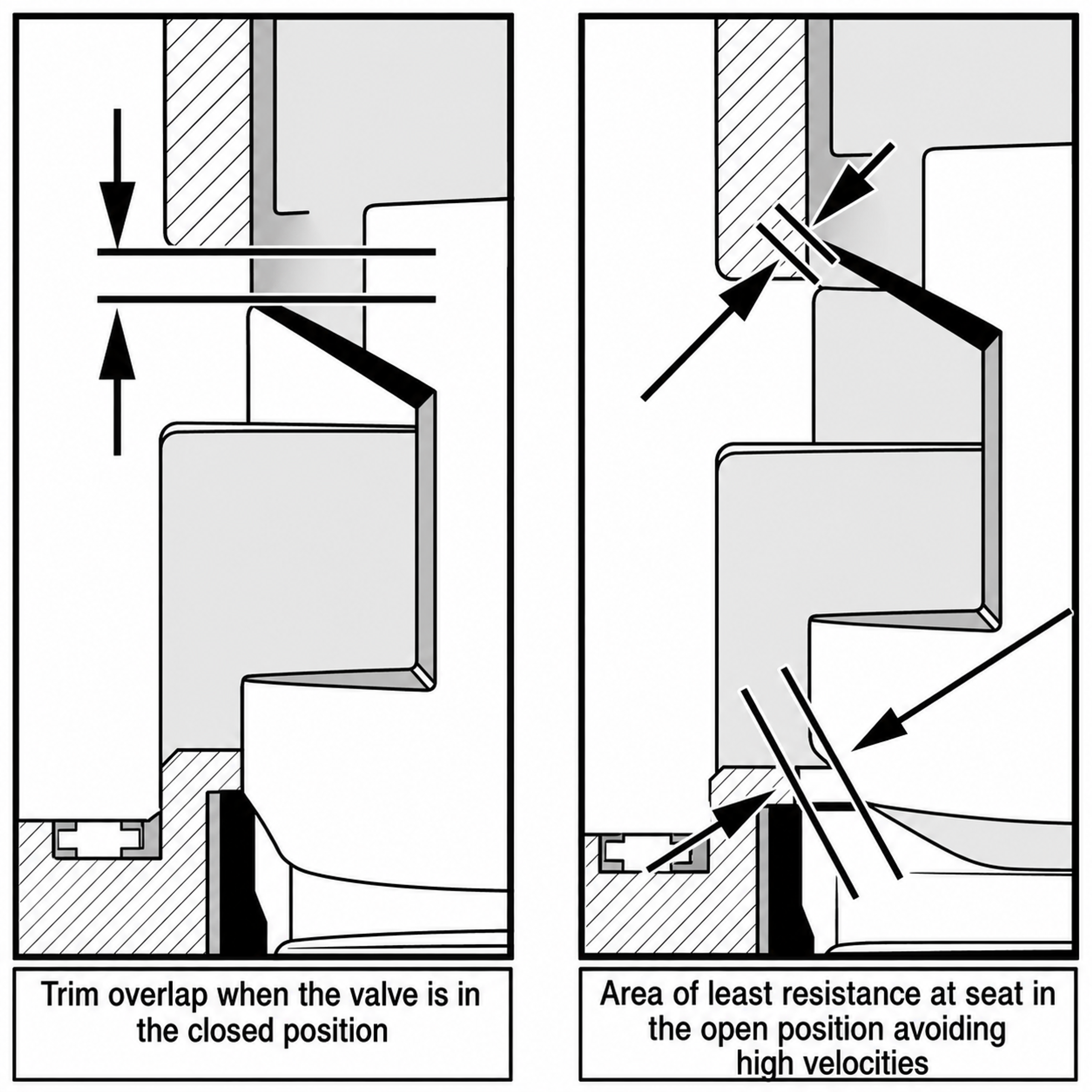
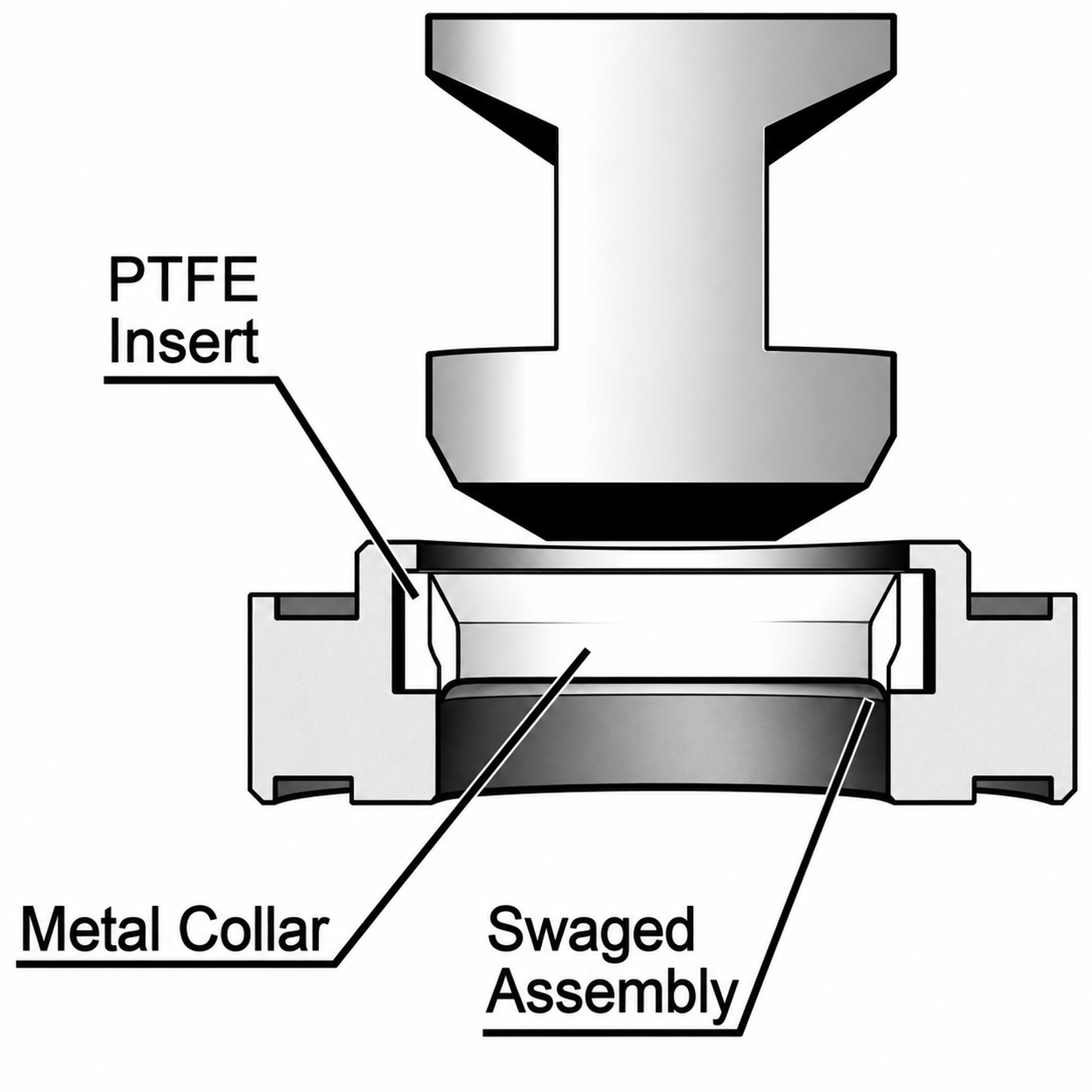
Figure 17. Separation of shutoff and throttling functions in an axial multistage trim.
4.7 Manage Outlet Velocity and Gallery Flow
A large valve body is not inherently excessive. The body gallery must maintain adequate separation between the cavity field and the pressure boundary while distributing flow uniformly around the trim. A preliminary outlet velocity is
The Valtek sizing guide recommends approximately 9.1 meters per second as a practical limit for cavitating or near-saturation liquid service, whereas SAMSON guidance for cavitating operation uses a more conservative outlet velocity near 4 meters per second for its erosion limits. These values are design guides rather than universal limits. The appropriate criterion depends on valve geometry, pressure, fluid properties, piping, and manufacturer experience. [3, 13]
4.8 Consider the Process Loop Before Adding Trim
Cavitation can sometimes be reduced by relocating the valve so that a larger fraction of system resistance remains downstream, thereby increasing valve outlet pressure. Discharge into a vessel, use of a downstream diffuser, or redistribution of pressure drop among several devices can also be effective. A downstream orifice plate can reduce the pressure drop across the valve, but it may transfer cavitation to the plate and is effective only over a limited flow range. [4, 5, 11, 15]
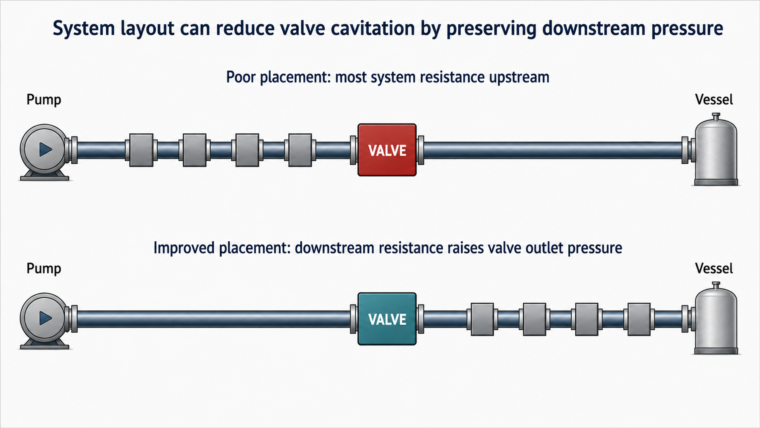
Figure 18. Effect of valve location on available downstream pressure.
5. Anti-Cavitation Trim Architectures
5.1 Perforated Cages and Opposed-Jet Trims
Perforated-cage trims distribute multiple holes around a cylindrical retainer. Hole diameter and spacing determine capacity and flow characteristic, while opposed pairs provide mutual jet impingement. A closely guided plug progressively uncovers rows of holes as it moves, allowing the cage characteristic to be tailored. These trims are compact and economical for clean liquids, but close plug-to-cage clearances and small holes are susceptible to dirt, scale, weld debris, and galling. [1, 2, 5, 11, 12]
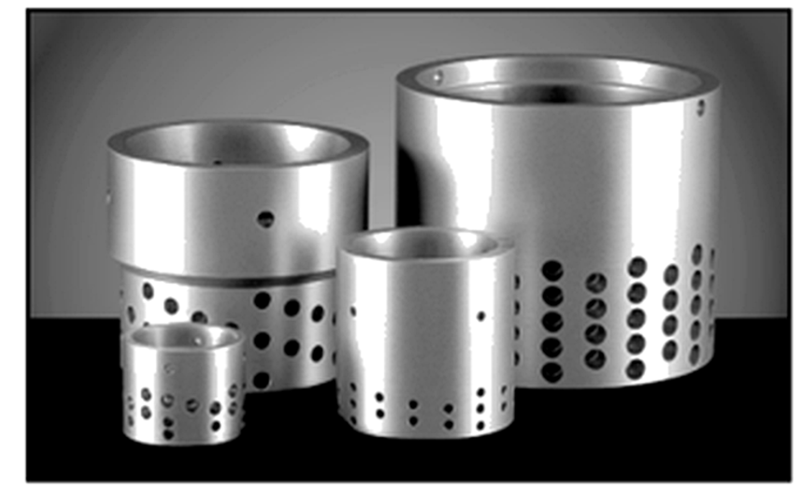
Figure 19. CavControl trim.
CavControl uses multiple small, diametrically opposed flow holes in a special seat retainer (Figure 19). Flow is directed over the plug. As the plug lifts from the seat, successive pairs of holes are uncovered. Each hole produces a cavitating liquid jet that impinges on the opposing jet near the center of the retainer (Figure 20). The resulting interaction creates a central recovery region that promotes vapor collapse away from metal surfaces. Stepped holes are used to favor orifice-type rather than tube-type behavior so that the vena contracta forms outside the retainer passage. [1]
Table 1. CavControl Trim Materials of Construction
| Trim Part | Available Materials |
|---|---|
| Seat Retainer | 316 stainless steel or 400 series hardened stainless steel |
| Plug | 316 stainless steel with Alloy 6 facing or 400 series hardened stainless steel |
| Seat Ring | 316 stainless steel with Alloy 6 facing or 400 series hardened stainless steel |
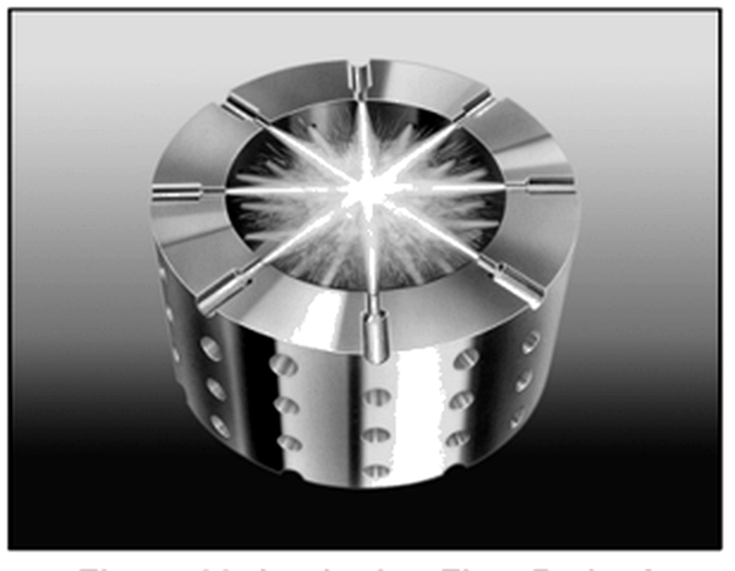
Figure 20. CavControl cage, impinging flow path.
Flow capacity and characteristic are governed by the diameter and spacing of the holes in the seat retainer.
Different hole diameters and spacing patterns can be combined on a single retainer to obtain the required flow characteristic.
Application capacity can be calculated using standard ISA sizing equations. Relative to a conventional globe valve, the CavControl trim is designed for lower pressure recovery and reduced susceptibility to liquid choking, so a given flow coefficient can pass a larger flow at the same pressure drop when the applicable tested coefficients support the calculation. [1]
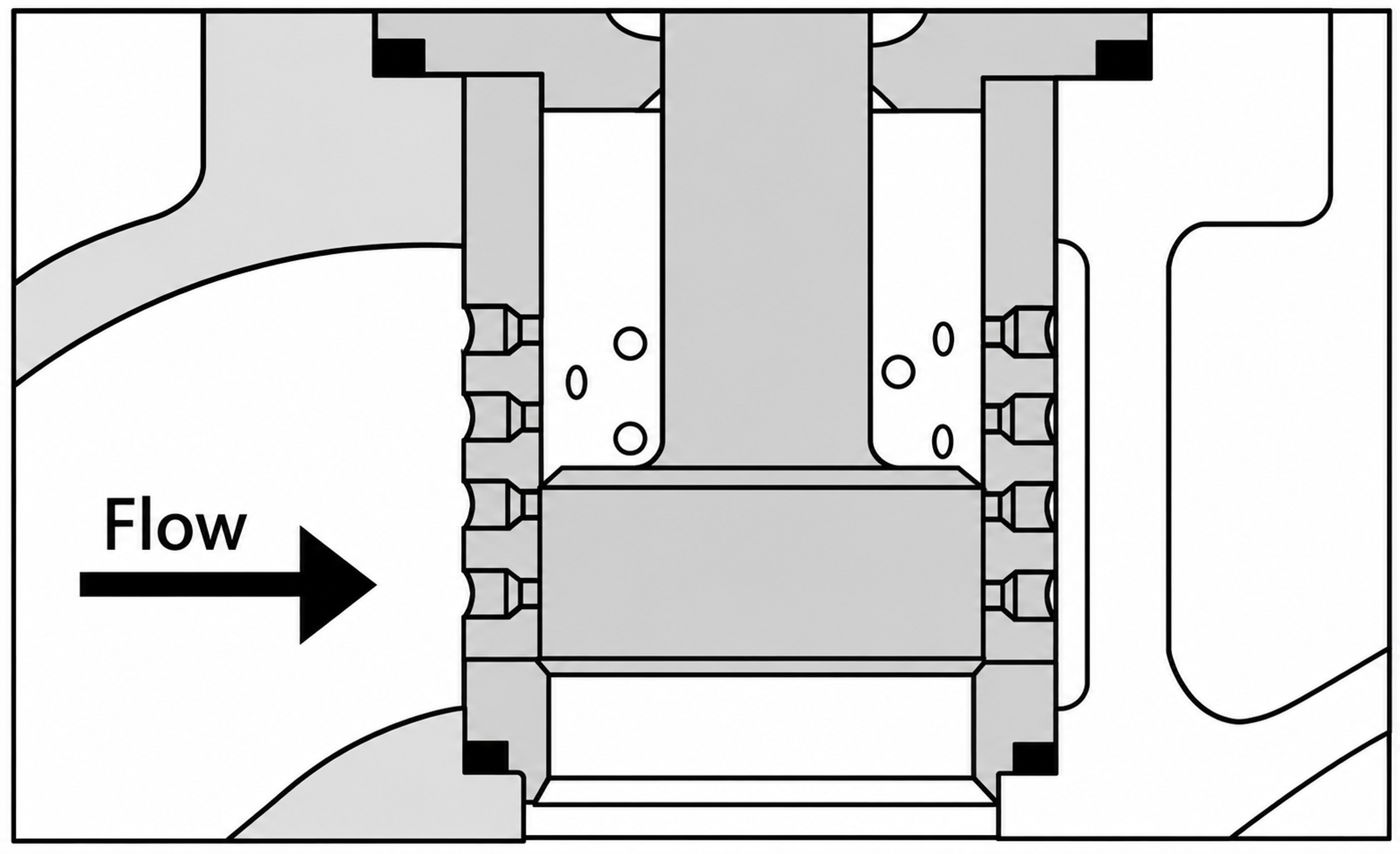
Figure 20. Mascot CavFlo opposed jet trim and pressure profile.
Mascot CavFlo similarly uses multiple small holes for diametrical flow through the seat retainer. As the plug lifts, additional opposed hole pairs are uncovered, and the corresponding cavitating jets impinge near the center of the retainer. [12]
Table 2. Standard Materials of Construction
| Trim Part | Standard Material |
|---|---|
| Seat Retainer | 316 stainless steel or 416 hardened stainless steel |
| Plug | 316 stainless steel with Stellite facing |
| Seat Ring | 316 stainless steel with Stellite facing |
Because the plug closely guides within the retainer while regulating flow through the holes, the fluid must be sufficiently clean to prevent seizure caused by dirt or pipe debris. Hole diameter and spacing determine flow capacity and characteristic. Variable hole sizes and spacing can be combined to obtain the required characteristic. CavFlo is configured for flow over the plug. [12]
5.2 Dual-Cage and Waterworks Valves
Large water-distribution valves may use two sliding perforated sleeves within an automatic valve body. The first cage produces an initial pressure reduction and contains the corresponding recovery region, while the second cage provides additional control toward the downstream pressure. The orifice pattern is selected for the specified inlet-pressure, outlet-pressure, and flow envelope. This arrangement avoids reliance on a fixed downstream orifice whose effectiveness decreases at low flow. [4, 5, 11]
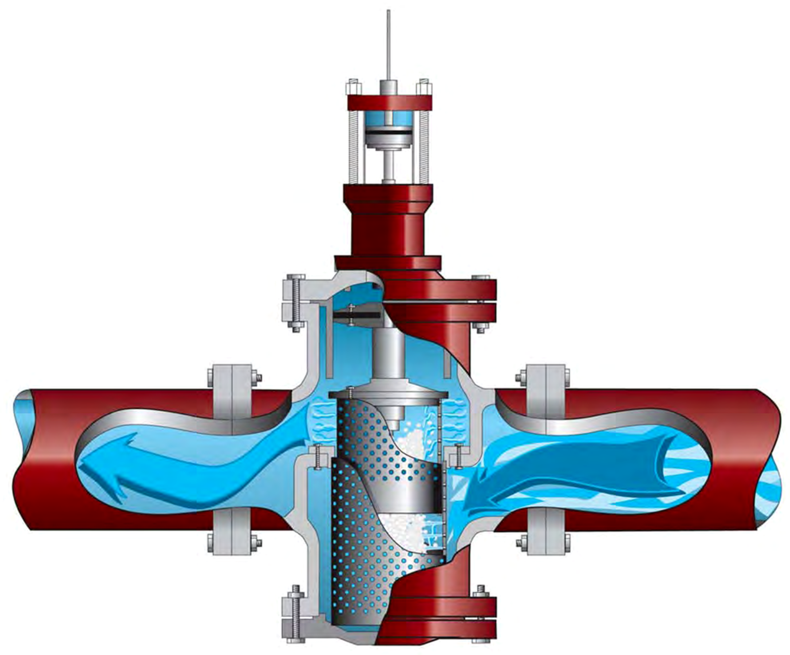
Figure 21. Ross WaterTamer anti-cavitation valve cutaway.
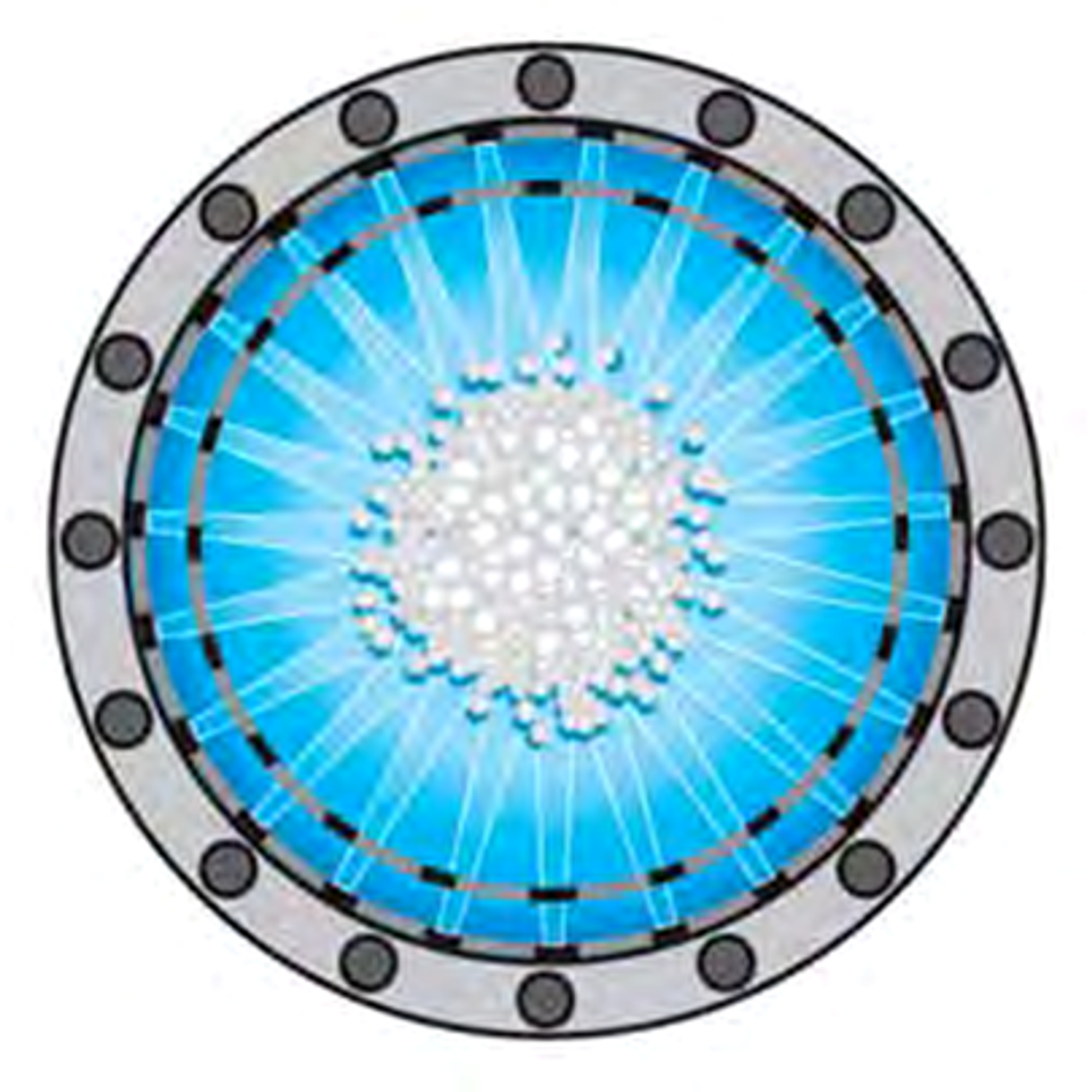
Figure 22. Top view of the WaterTamer nozzle arrangement and central cavitation region.
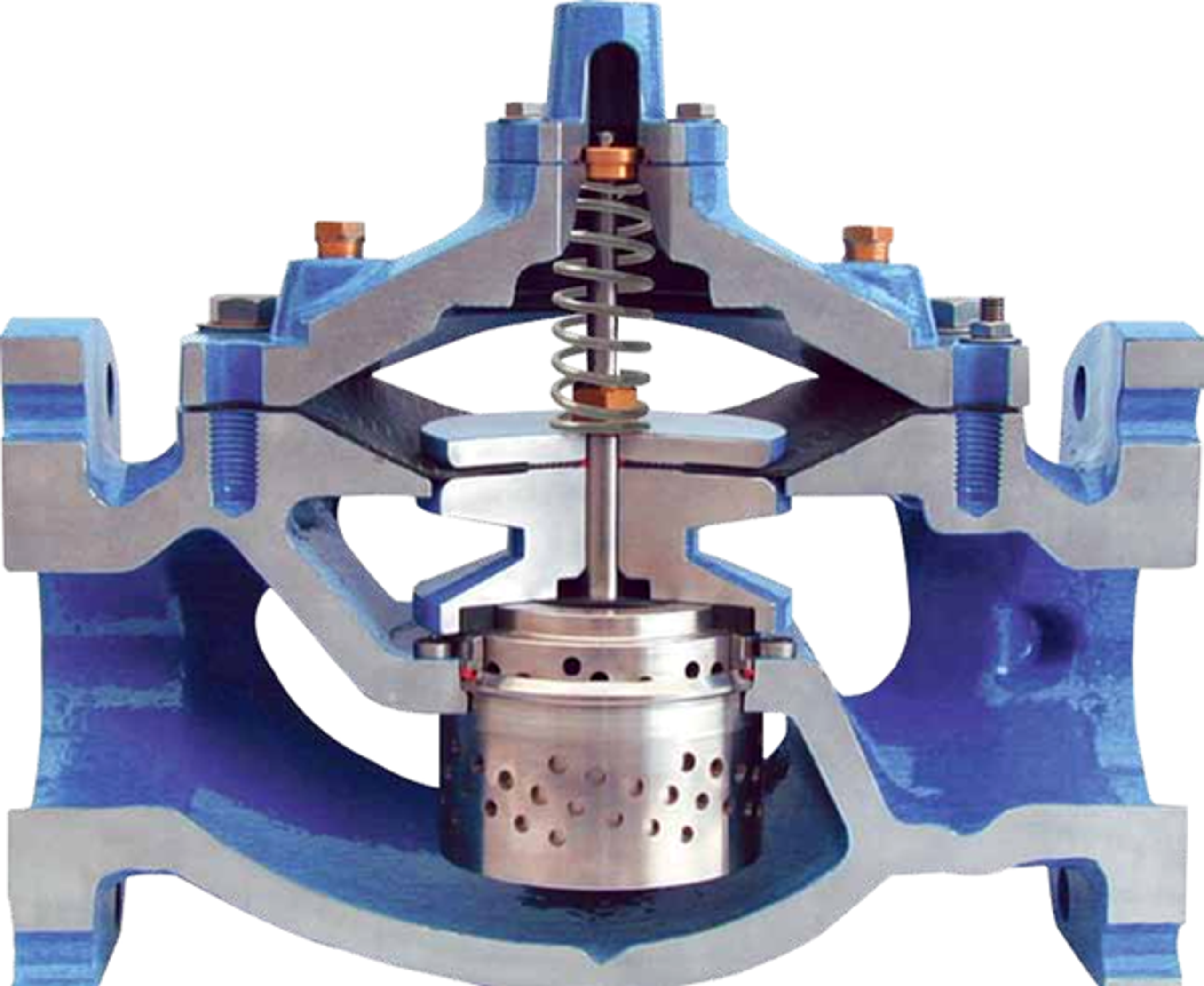
Figure 23. Singer Model 106-PG-AC dual-cage anti-cavitation valve cutaway.
Ross WaterTamer uses inner and outer chambers with opposed nozzles so that the cavity field is concentrated within a central water column. Singer uses dual sliding cages with application-specific round holes. Both approaches show that large waterworks valves require uniform circumferential entry, adequate body clearance, and strong guidance to maintain a symmetric collapse region. [4, 5, 11]
5.3 Stacked-Disk and Expanding-Tooth Trims
Stacked-disk trims create numerous parallel passages within a cylindrical stack. Individual paths may contain teeth, grooves, turns, restrictions, and expansion regions. In the Tiger Tooth design, flow passes radially through a sequence of expanding teeth. Smaller upstream teeth impose a larger fraction of the initial pressure drop, while larger downstream passages limit later-stage velocity and pressure excursions. Disk stacks can be characterized by varying the number, size, and arrangement of flow paths. [1, 2]
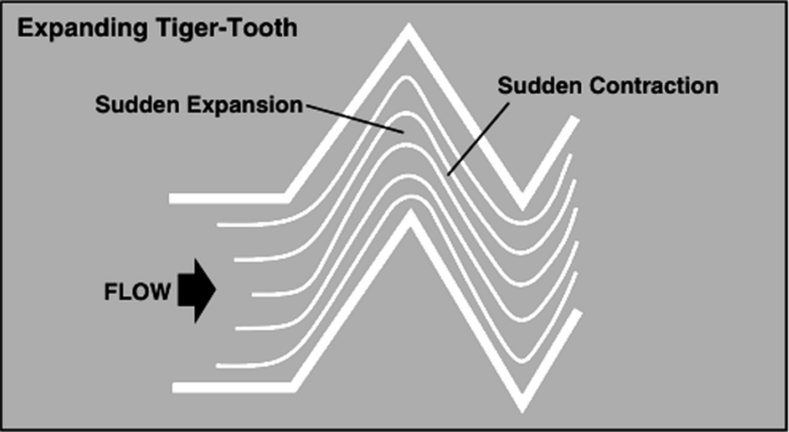
Figure 24: Sudden Expansion and Contraction Caused by Tiger-Tooth Design.
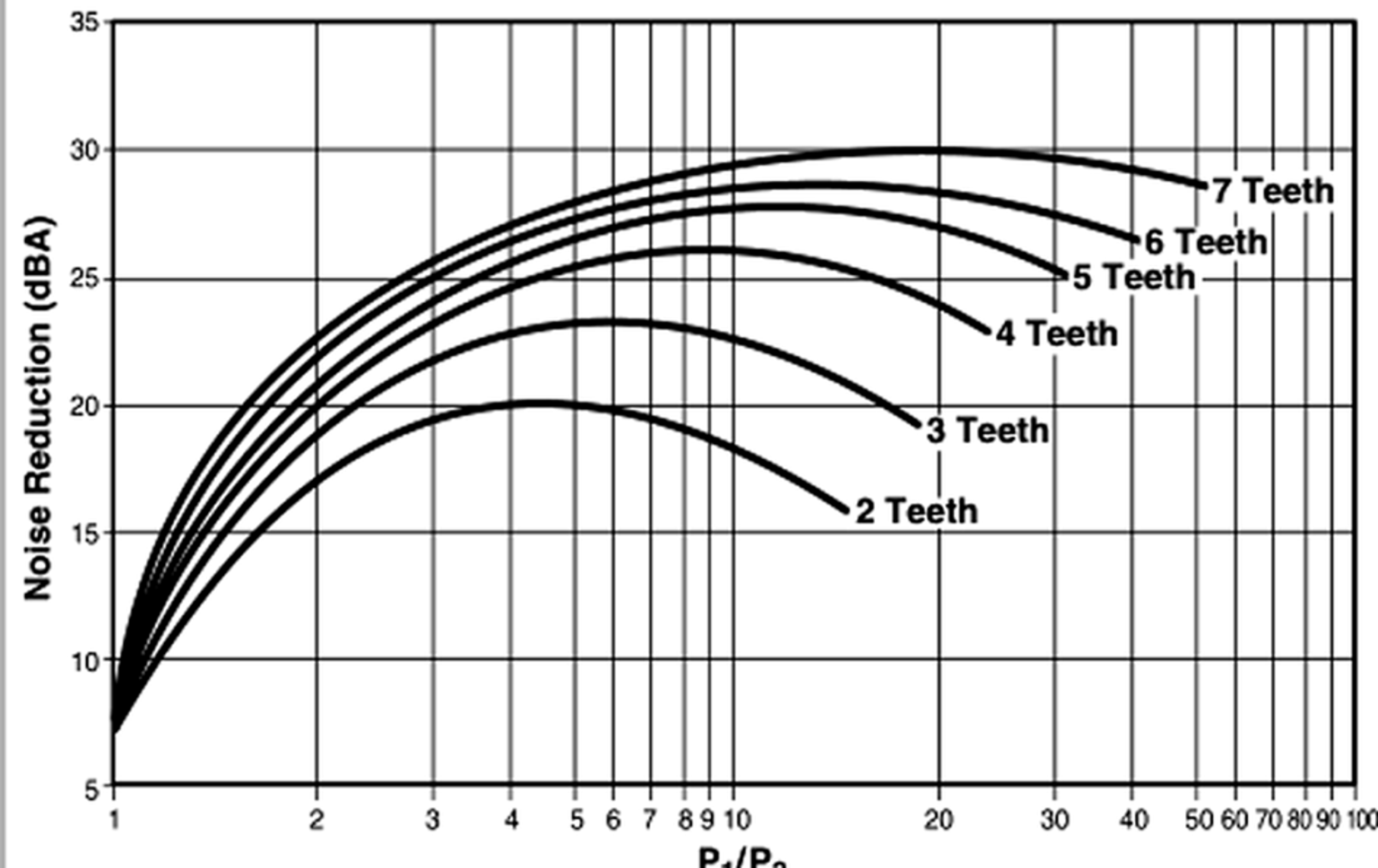
Figure 25: Noise Reduction vs. Number of Tiger-Tooth Teeth.
Table 3: Tiger-Tooth Materials of Construction
| Trim Part | Available Materials |
|---|---|
| Stack | Aluminum-Bronze, 410 stainless steel, 316 stainless steel, 316 stainless steel with Alloy 6 overlay, other alloys as required |
| Plug | 316 stainless steel, 316 stainless steel with Alloy 6 overlay, other alloys as required |
| Seat Ring | 316 stainless steel, 316 stainless steel with Alloy 6 overlay, other alloys as required |
Disk stacks provide high hydraulic resistance within a compact diameter, but narrow passages are susceptible to plugging and must be checked against the maximum credible particle size. Designs with open radial passages and without horizontal ledges are generally more tolerant of contamination than fine labyrinth stacks. Maintenance requires access for passage inspection and verification of stable plug guidance throughout the stroke. [1, 2, 10, 14]
5.4 Intersecting-Channel and Concentric-Sleeve Trims
ChannelStream uses staged cylinders and intersecting channels so that flow repeatedly passes through restrictions, channels, expansion regions, and impingement zones. Low-flow versions place stages in the plug head, permitting very small flow coefficients but requiring exceptionally clean service. Gestra ZK uses concentric perforated sleeves with shifted or partly overlapping openings that form serial nozzles separated by intermediate chambers. The standard ChannelStream trim is intended for flow coefficients of 2.5 Cv and above and uses a cartridge in place of a seat retainer. Flow passes over the plug through a series of close-fitting cylindrical stages containing expansion holes and intersecting circumferential channels (Figures 26 and 27). [1, 2]
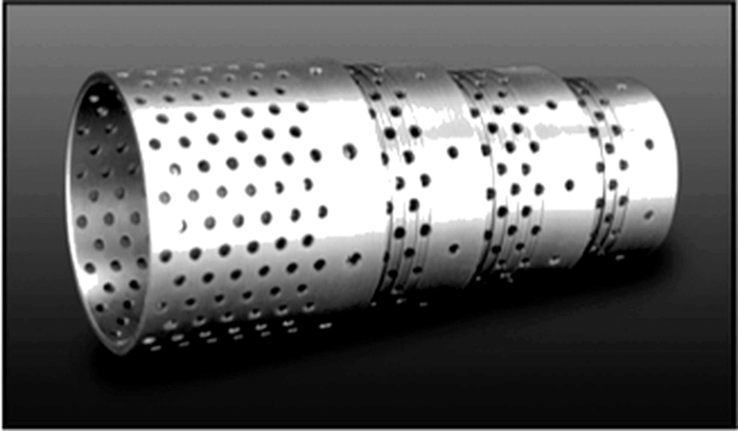
Figure 26. ChannelStream cartridge showing individual stages.
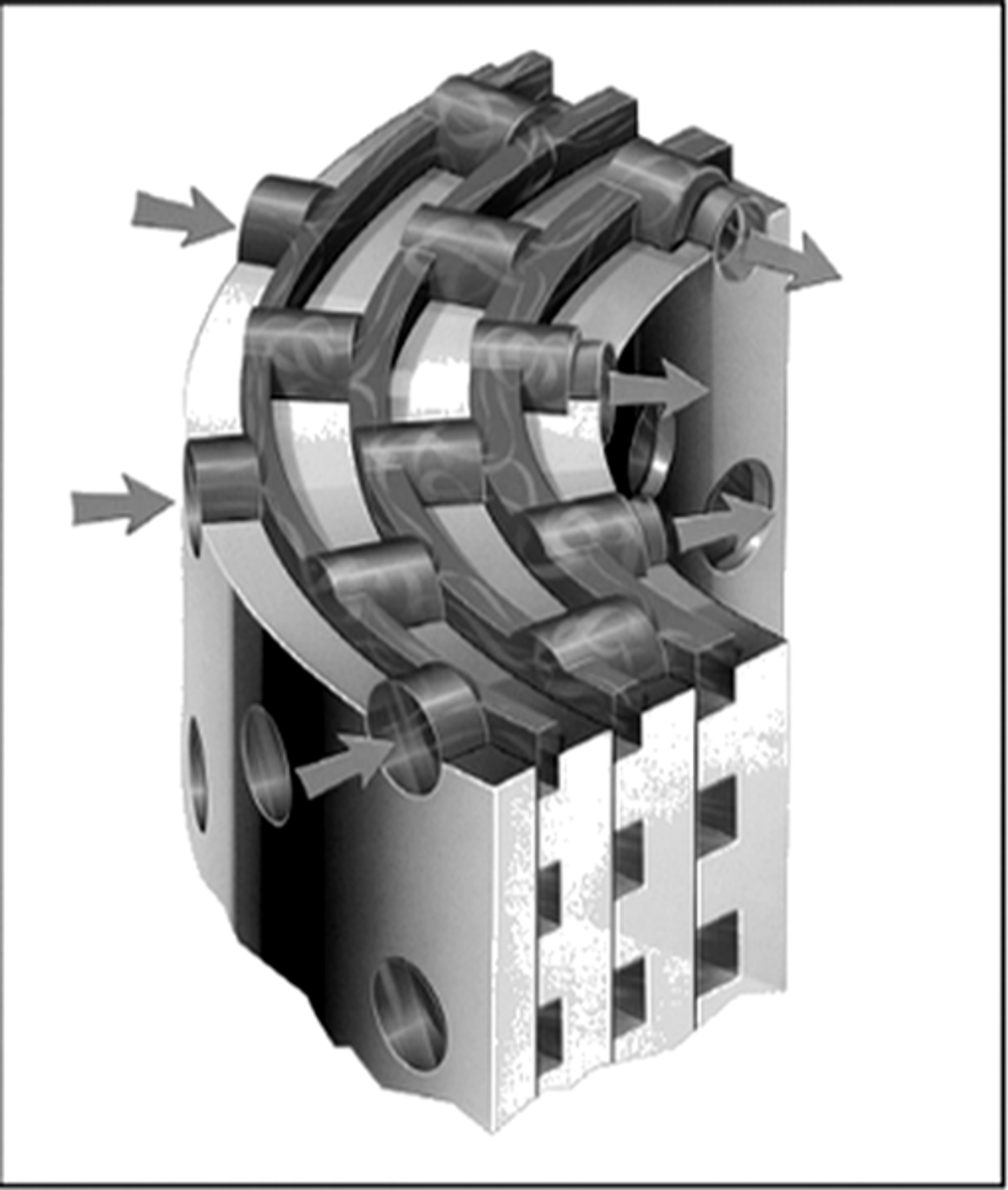
Figure 27. ChannelStream cartridge and three-dimensional flow path.
Concentric-sleeve construction also appears in early patent literature. US3917221A describes nested perforated cylindrical cages for staged pressure reduction. Later patents modify aperture shape, wetted perimeter, and the relationship between throats and expansion chambers to increase hydraulic resistance while preserving capacity. [26, 30]
5.5 Labyrinth and Cascade Trims
Cascade trims machine a sequence of grooves or contoured steps into the plug and cage so that fluid follows a long single path. The total pressure drop is divided among the grooves, limiting pressure recovery at any one location. At low flow, the plug remains close to the seat and the full cascade is active. At higher flow, some designs progressively bypass early grooves as process pressure drop decreases. Super Cascade and top-guided variants retain staged pressure reduction through a larger fraction of travel. [6-8]
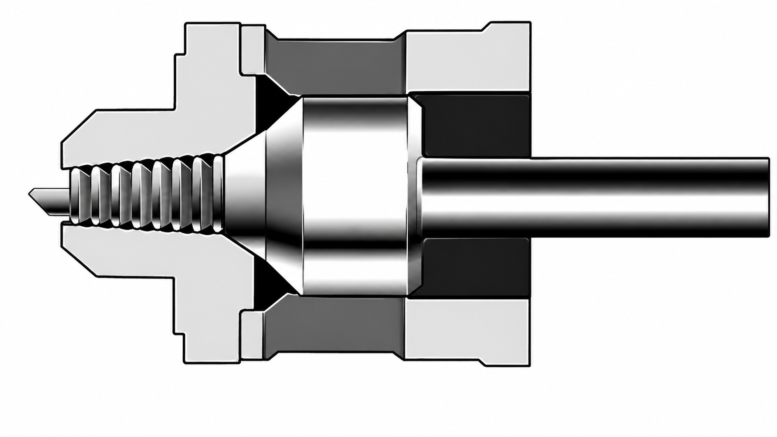
Figure 24. Cascade and labyrinth trim examples from Copes Vulcan and Valvitalia.
Copes Vulcan literature describes hot-water testing at very high differential pressure in which hardened Type 420 stainless-steel trim remained serviceable. The Valvitalia bulletin distinguishes cage-guided and top-guided cascade trims. Cage-guided construction is intended for larger ports and dirty or mildly abrasive service because its passages and plug-shearing action reduce the risk of clogging. Top-guided construction provides up to sixteen stages for small flow coefficients. [6, 7]
5.6 Axial Multistage Trims
In axial trims, flow proceeds along the valve axis through a sequence of notches, liners, or cages. When all stages throttle simultaneously, no stage becomes inactive at partial travel. This arrangement reduces the risk that inner stages become oversized while a final controlling edge carries most of the pressure drop. Axial staging also permits relatively large passages, strong plug guidance, and deliberate separation of the shutoff seat from the pressure-reducing elements. [3, 9, 10]
The LincolnLog design uses a sequence of three-dimensional, high-impedance pressure-reduction stages. The tortuous axial flow path distributes pressure loss and controls velocity through multiple active stages rather than concentrating the differential at a single restriction. [10]
Manufacturer literature describes LincolnLog configurations with as many as ten pressure-reduction stages for high-pressure liquid-letdown applications and pressure drops exceeding 8000 psi (approximately 550 bar). The design is intended for severe and remote services, including wellhead injection and offshore installations, where stage-by-stage pressure control is required. [10]
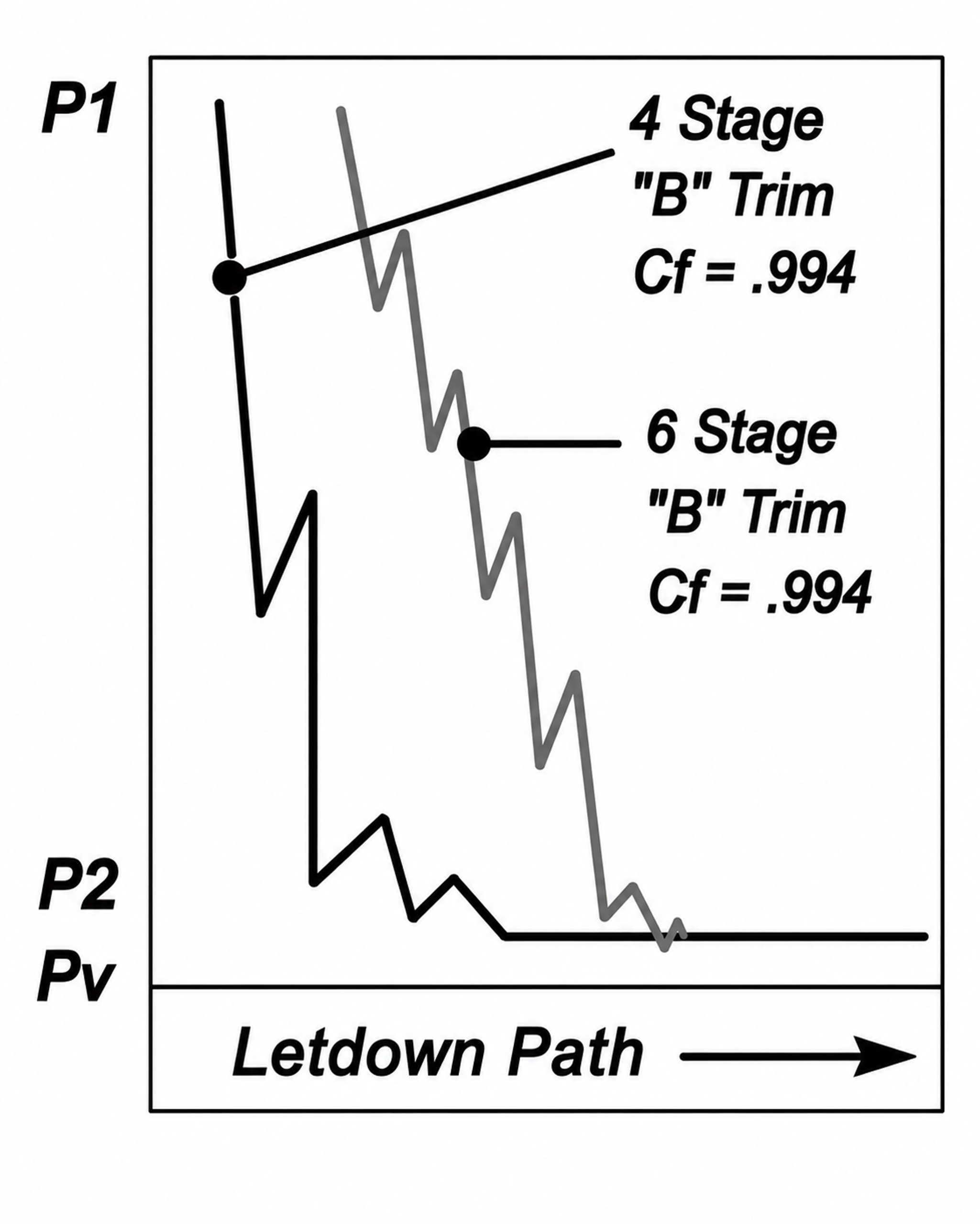
Figure 25. Multistage trim comparison for four- and six-stage configurations.
The axial arrangement throttles all stages concurrently throughout plug travel, limiting concentration of velocity and pressure drop at a single leading or controlling edge. The design objective is to reduce wear on the plug, cage, and seat by distributing the hydraulic load among the active stages. [10]
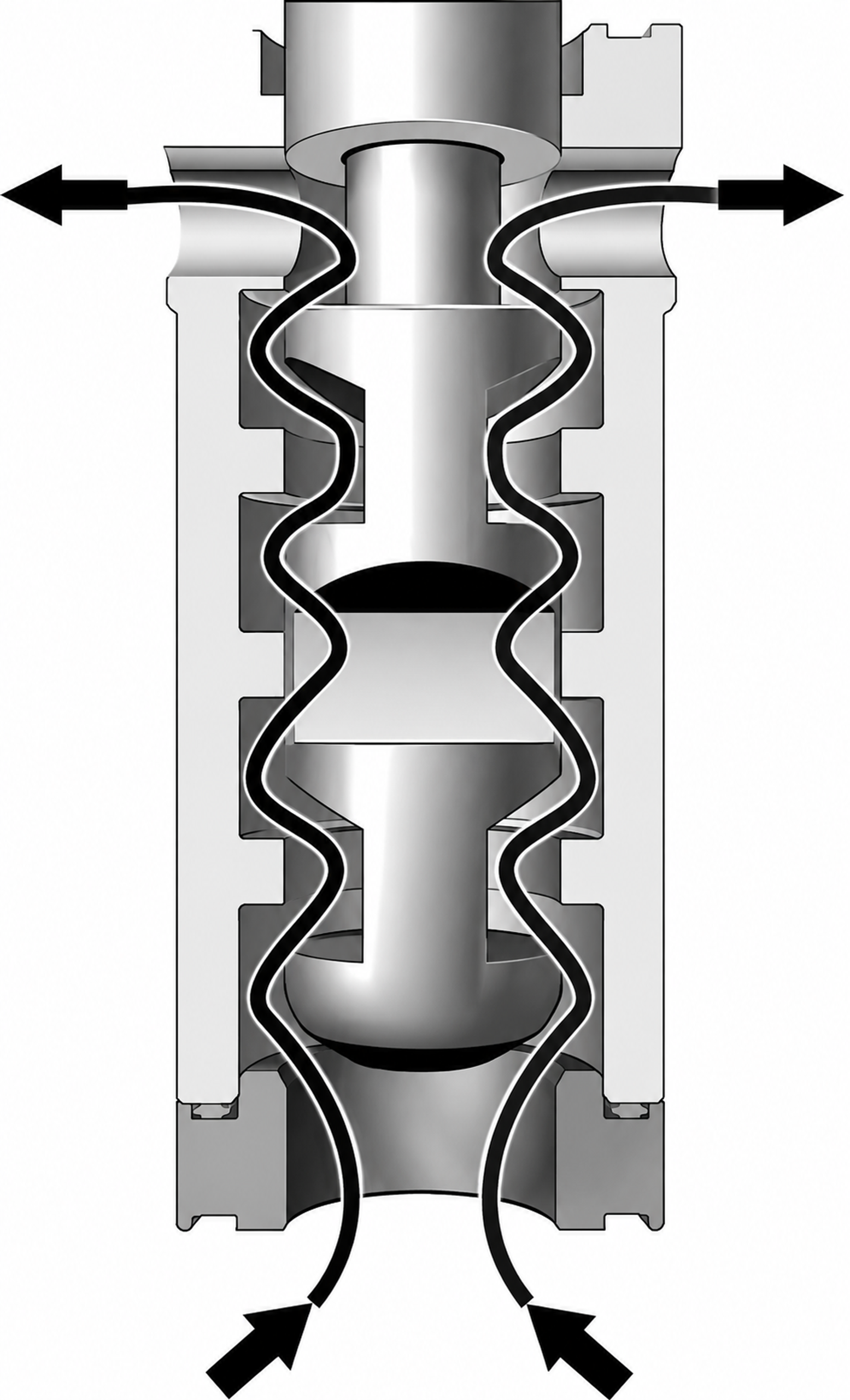
Figure 26. Axial-flow technology with three-dimensional multistage pressure reduction.
LincolnLog literature describes configurations with three to ten axial stages for high-pressure liquid letdown, with relatively large passages for debris tolerance and simultaneous stage activity throughout the stroke. The trim can be installed in globe or angle bodies and uses substantial plug guidance, hardened materials, and protected seats. [10]
5.7 Multistage Multipath Trims
Multipath trims divide total flow among numerous tortuous passages. The MIL Matrix concept combines axial or radial flow with a three-dimensional welded cage assembly and progressively expanding passages. Manufacturer literature describes very low pressure recovery, multiple pressure- and velocity-reduction stages, and designs with up to approximately fifty stages. The large number of small losses produces a gradual pressure decline rather than a few large pressure steps. [9]
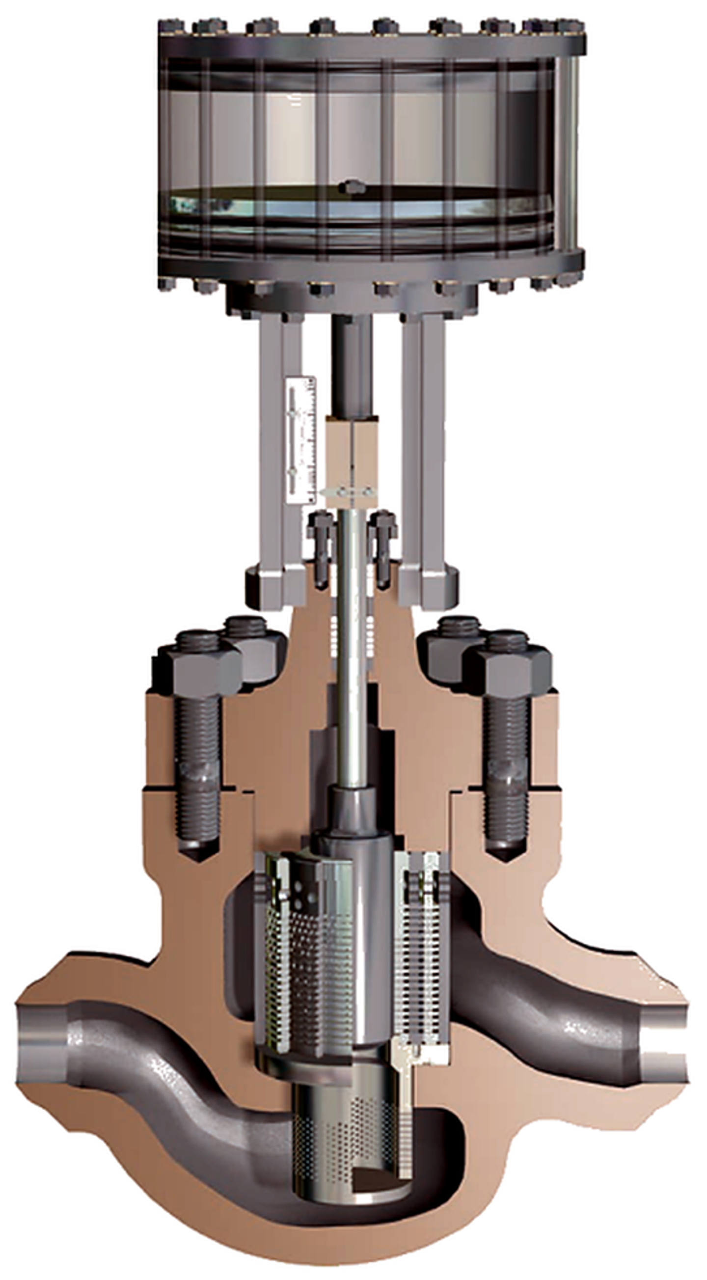
Figure 27. MIL Matrix multistage multipath control valve cutaway.
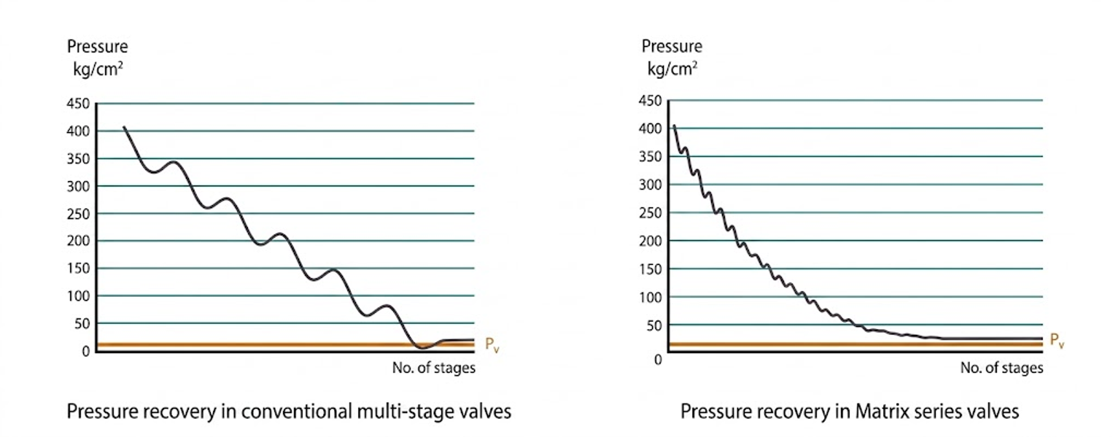
Figure 27. Comparison of conventional multistage pressure recovery with a progressively declining Matrix profile.
5.8 Dirty-Service Trims
Dirty-service design begins with the largest credible particle rather than the average solids concentration. The trim should provide a continuous passage larger than the design particle, minimize dead pockets, resist abrasive cutting, and protect the seat. Fisher Dirty Service Trim combines axial and radial flow paths, expanding flow area, a protected seat, and openings intended to pass relatively large particulate. Product literature states that a substantial portion of the total pressure drop is imposed before the final stage, reducing severity at the exit. [15]
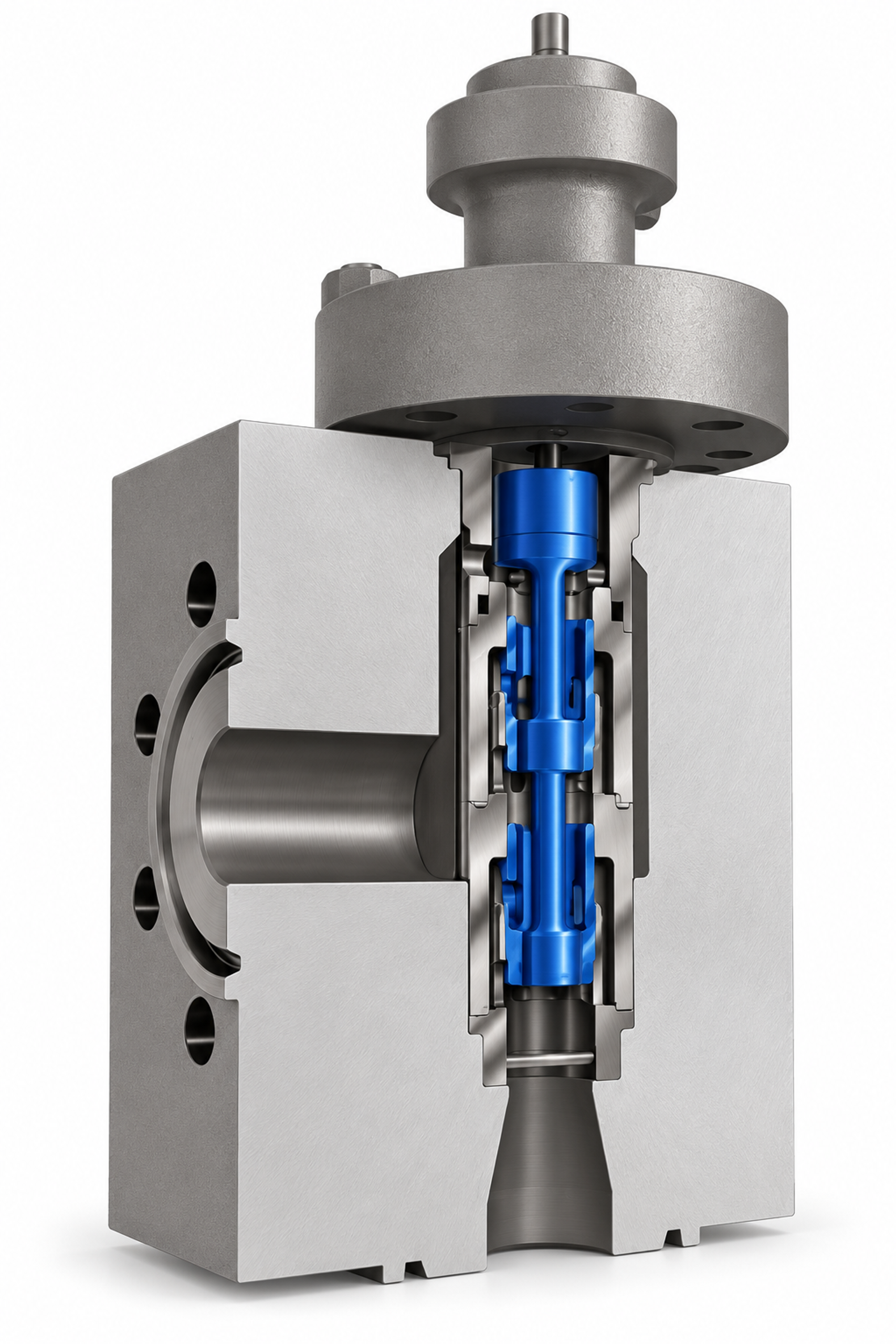
Figure 28. Fisher Dirty Service Trim for high-pressure-drop and particulate service.
Large-passage axial trims and cage-guided cascade trims provide alternative approaches for contaminated service. Fine ChannelStream, MicroCav, close-fitting perforated cages, and compact disk labyrinths are better suited to clean fluids unless adequate strainers and a defined cleanliness program are provided. [1, 2, 7, 10, 14, 15]
5.9 Rotary-Valve Cavitation Control
Rotary valves provide high capacity and compact construction, but conventional ball and butterfly valves can exhibit high pressure recovery and may cavitate at relatively modest pressure ratios. Cavitation control can be improved with characterized balls containing tortuous channels, downstream diffuser elements, or integral inserts containing repeated throats and expansion chambers. Rotary solutions are attractive when line-size capacity or solids tolerance is required, but trim effectiveness must be verified over the full range of rotation. [2, 15, 30]
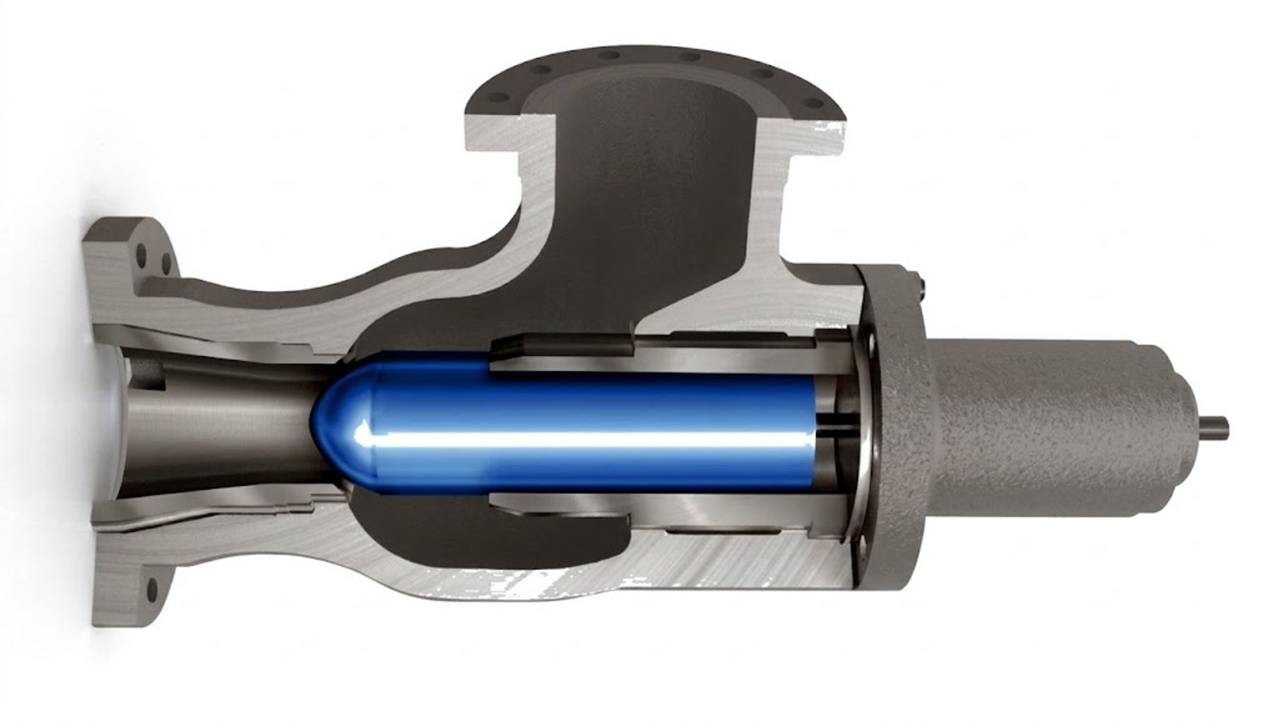
Figure 29. Fisher 461 sweep flow angle valve used for erosive and cavitating applications.
5.10 Fixed Energy Dissipators and Downstream Devices
A fixed multiorifice device can be effective when flow and pressure conditions remain relatively constant. Ross Model 890 uses an engineered multiorifice plate arrangement to dissipate hydraulic energy and limit large-scale eddies, while the Ross MOV uses two perforated plates whose relative alignment changes with travel. Fixed devices are mechanically simple and robust but cannot maintain an optimal pressure profile over a wide flow range. [4]
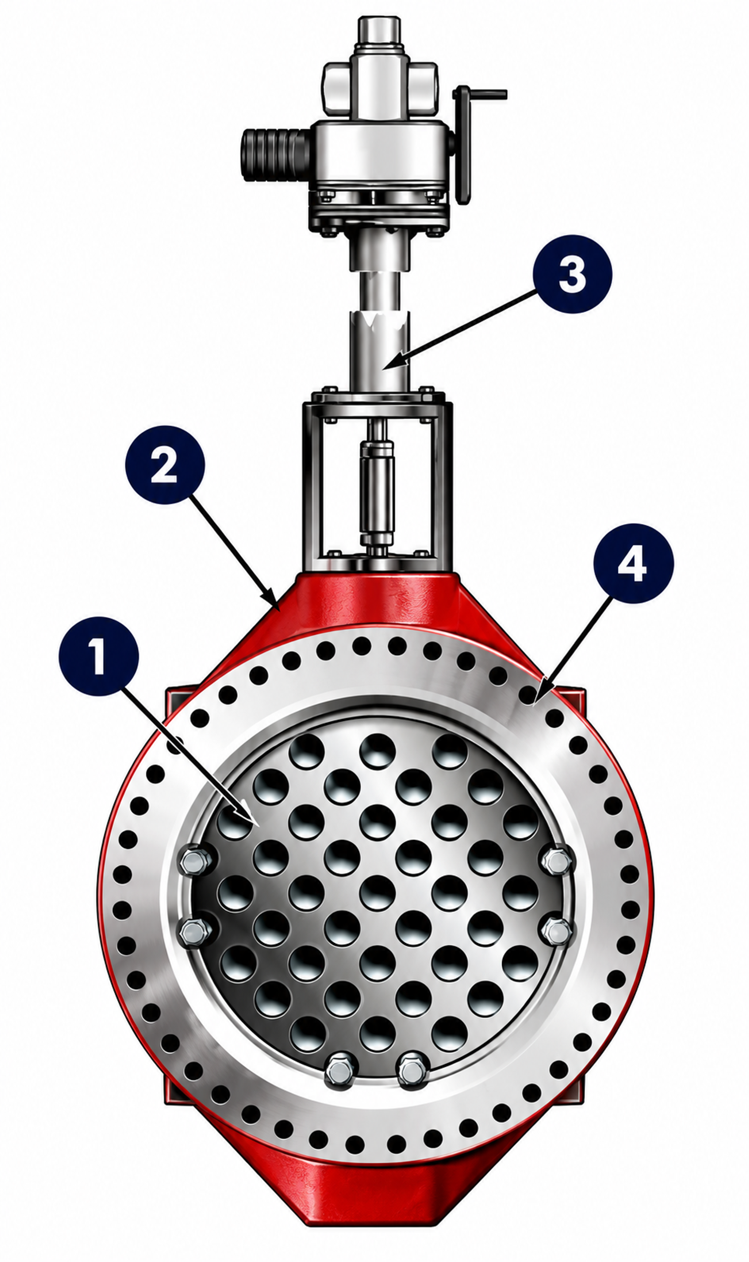
Figure 30. Ross Model MOV valve and numbered key features. 1 Two hardened stainless steel plates with custom designed orifices direct water to center of downstream pipe, safely dissipating energy. 2 Rugged construction throughout with heavy-duty shafts, bearing guides and seals. 3 Available automated or manual controls. 4 Narrow profile “space saving” design. Source: Ross Valve [4].
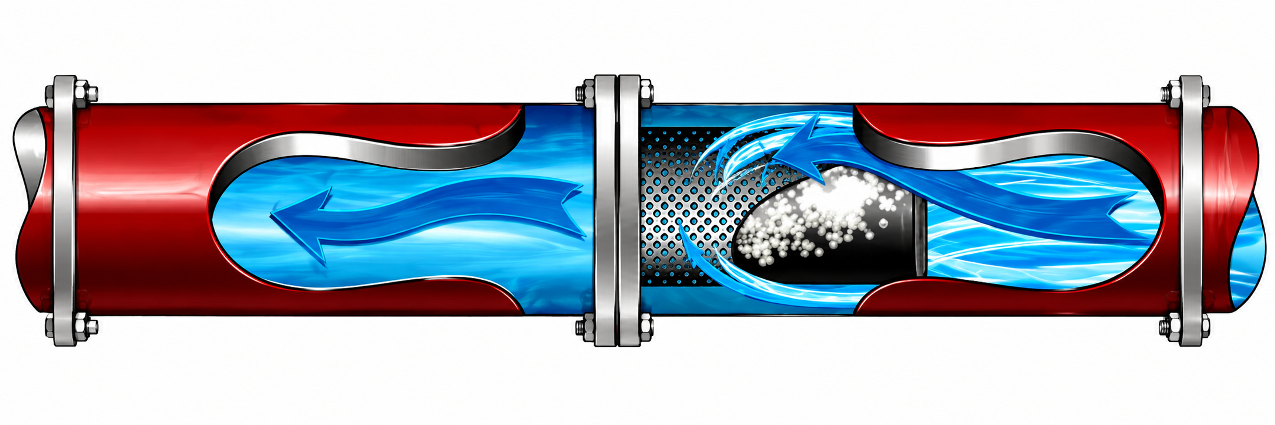
Figure 31. Ross Model 890 fixed energy dissipator flow.
6. Materials and Mechanical Design
6.1 Hydraulic Design First, Material Hardness Second
Hardening alone does not eliminate cavitation; it only delays material loss while collapse energy remains. Durable severe-service valves combine a hydraulic pressure profile that limits cavity intensity with materials capable of resisting the remaining mechanical and chemical attack. Martensitic stainless steels, precipitation-hardened stainless steels, cobalt-chromium hardfacing, nickel-chromium-boron alloys, and tungsten carbide are among the materials used for severe trim. [1-3, 6-10, 12, 15]
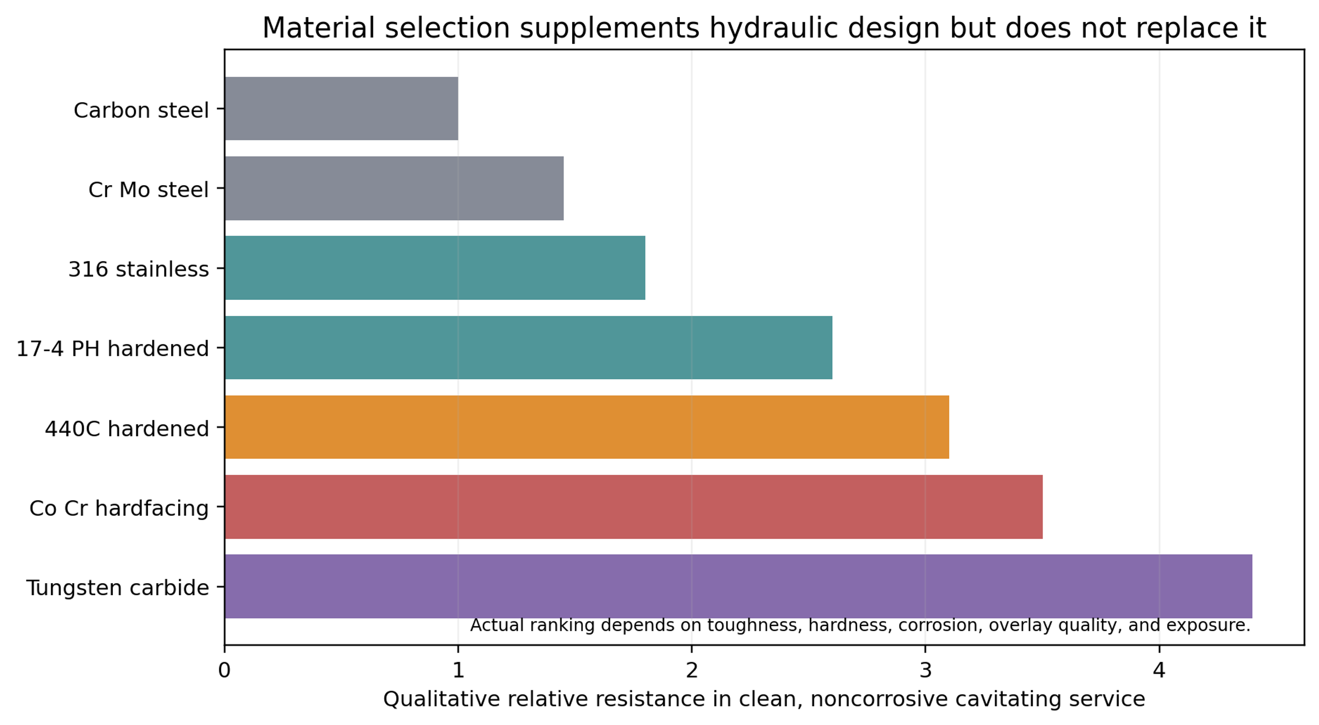
Figure 32. Qualitative material resistance comparison.
The qualitative ranking in Figure 32 is not a procurement specification. Toughness, yield strength, fracture strain, hardness, corrosion resistance, overlay dilution, porosity, residual stress, joining method, and thermal cycling can all affect performance. In corrosive liquids, corrosion resistance may be more important than hardness because repeated cavitation impacts remove protective passive films. [3, 15]
6.2 Material Property Relations
SAMSON summarizes experimental work correlating cavitation resistance with deformation energy to fracture. A simplified proportionality is
where is the energy absorbed per unit volume before fracture. This explains why hardness alone does not fully predict cavitation resistance. A brittle very hard material can crack under repeated impact, while a tougher material may absorb more energy. [3]
6.3 Plug, Stem, Cage, and Seat Stability
High-pressure liquid forces can excite lateral plug motion and stem vibration. Severe-service valves therefore use long guiding surfaces, large stems, robust plug-to-stem connections, rigid cage stacks, and actuators with adequate stiffness and thrust margin. Misalignment increases local clearance, creates asymmetric jets, and accelerates erosion. [9, 10, 15]
Pressure-balanced plugs reduce actuator force but introduce balance seals and leakage paths that must tolerate temperature, particulate, and cycling. Unbalanced trims simplify sealing but require greater actuator force. Flow-to-open operation is often preferred for dynamic stability and seat protection, although the correct flow direction depends on body geometry and the required location of the pressure-recovery region. [1, 2, 7, 9, 10]
6.4 Shutoff and Leakage Class
The specified leakage class must be compatible with service temperature and pressure differential. Metal seats are common in high-temperature and abrasive service. Protected soft seats can provide tight shutoff at moderate temperature when a metal collar shields the polymer from direct flow. Pressure-reduction stages should not use the final shutoff edge as the principal throttling surface. [5, 7, 9, 10, 15]
6.5 Corrosion, Flashing, and Mixed Damage
Cavitation erosion, solid-particle erosion, corrosion, and flashing can occur simultaneously. Mixed damage changes surface morphology and can invalidate material selection based solely on clean-water testing. In flashing service, vapor persists downstream and the dominant damage mechanism may become high-velocity two-phase erosion rather than bubble collapse. Expanded outlets, angle bodies, hard materials, and downstream pipe protection may therefore be required. [1, 3, 13, 15]
7. Application Engineering and Selection
7.1 Required Process Data
A complete valve data sheet should include every relevant operating case, not only the design maximum. Minimum flow and startup can produce the highest pressure ratio, whereas maximum flow often governs body and passage velocity. The following information is required for a defensible selection.
| Category | Required data | Why it matters |
|---|---|---|
| Pressure | Minimum, normal, and maximum p₁ and p₂, all as absolute values | Establishes pressure ratio, choking, flashing, and actuator load. |
| Flow | Minimum controllable, normal, maximum, startup, shutdown, bypass, and relief flow | Determines rangeability, stage activation, and velocity. |
| Fluid | Composition, density, viscosity, vapor pressure, critical pressure, gas content | Controls capacity, nucleation, and collapse intensity. |
| Temperature | Normal and transient range | Changes vapor pressure, density, viscosity, materials, and seals. |
| Solids | Concentration, hardness, shape, maximum particle, expected debris | Determines minimum passage and erosion resistant material. |
| Piping | Line size, reducers, expanders, elevations, downstream resistance, vessel connection | Changes installed coefficients, outlet velocity, and recovery. |
| Control | Characteristic, fail action, stroke speed, shutoff class, actuator supply | Determines controllability and mechanical design. |
| Reliability | Required life, inspection interval, spare trim philosophy, acceptable noise and vibration | Sets margin, material, and maintainability. |
Table 2. Minimum information for anti-cavitation valve selection.
7.2 Severity and Fluid-Cleanliness Map
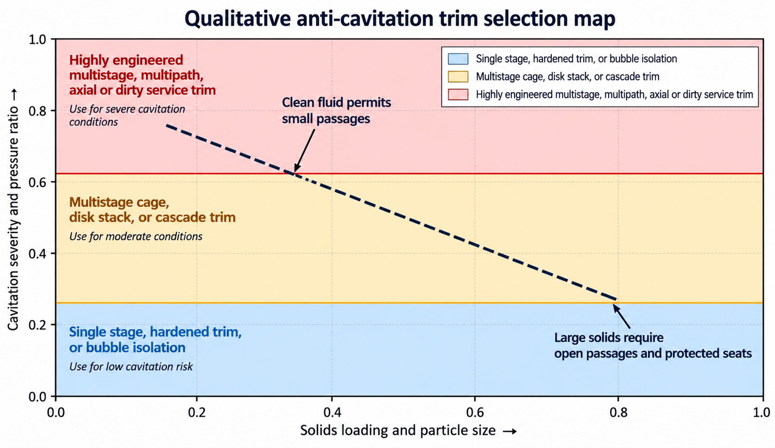
Figure 33. Qualitative selection map based on cavitation severity and solids loading.
The map is intentionally qualitative; vendor-tested coefficients define the actual application boundary. It illustrates a practical tradeoff: increasing cavitation resistance through smaller and more numerous passages generally increases sensitivity to solids. Dirty-service capability therefore tends to require greater trim volume, lower capacity for a given body size, or less compact flow geometry. [7, 9, 10, 14, 15]
7.3 Water Distribution, High-Rise, and Reservoir Service
Large automatic valves in water systems may reduce transmission pressure to a distribution zone, accommodate major elevation changes, fill elevated reservoirs, discharge to atmosphere, or provide continuous pressure relief. Singer literature uses an outlet pressure near or below approximately 30% of inlet pressure as a screening condition for anti-cavitation trim and illustrates a practical 3:1 pressure-ratio rule. This criterion is a screening aid and does not replace detailed calculation. [5, 11]
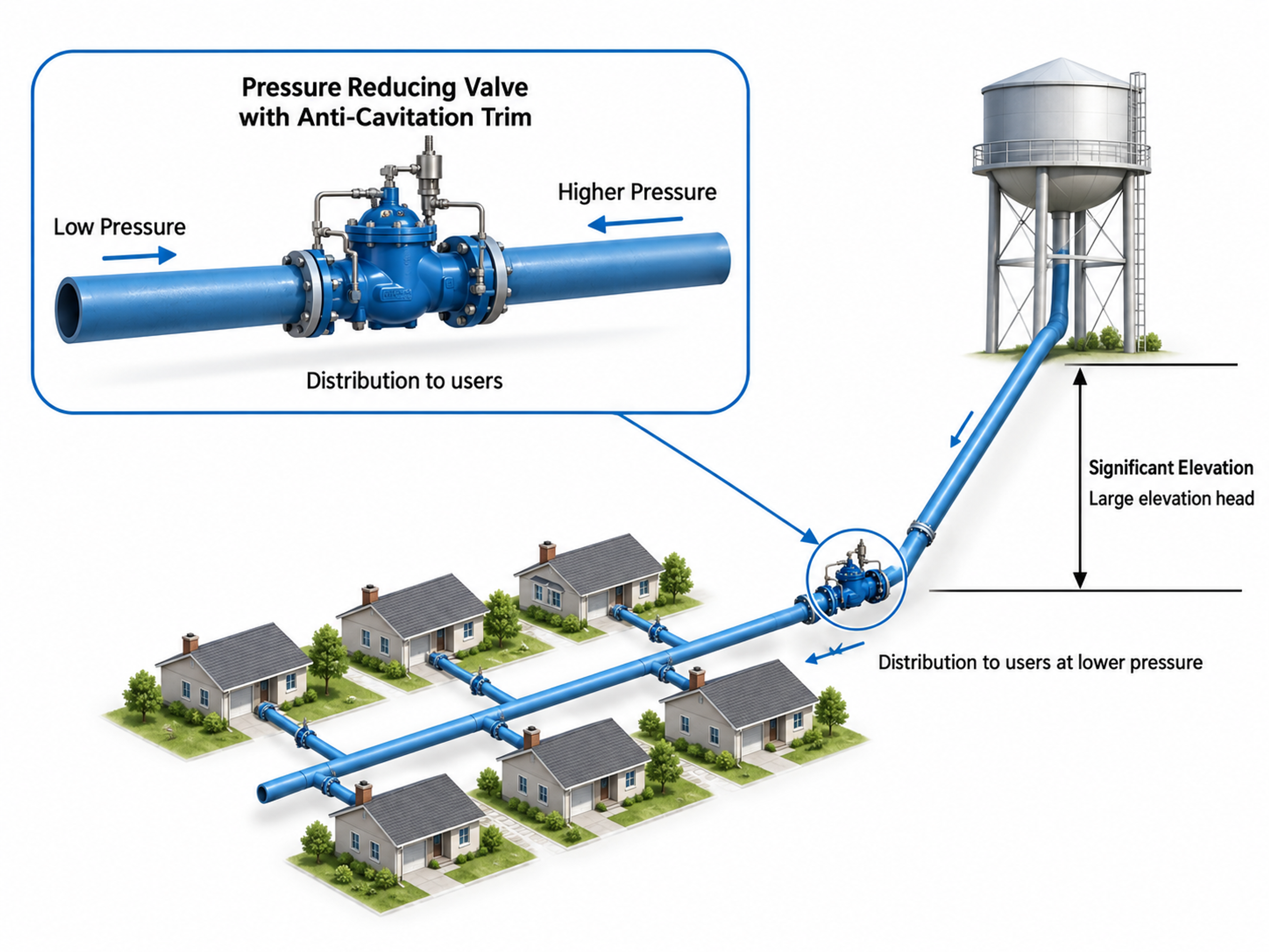
Figure 34. Water distribution pressure reduction application.
Reservoir filling to atmosphere and submerged discharge require particular attention because downstream static head, siphoning, and air entrainment can alter the actual outlet pressure. A discharge line that becomes submerged may develop a pressure profile different from the nominal atmospheric case. The complete line elevation and operating sequence should therefore be included in the hydraulic model. [4, 5, 11]
7.4 Power-Plant Service
Power plants contain several demanding liquid-valve applications, including boiler-feed-pump minimum recirculation, startup feed control, desuperheater and attemperator spray water, blowdown, drain, warmup, and injection service. A single valve may experience high inlet pressure, low outlet pressure, rapid transients, magnetite or weld debris, tight-shutoff requirements, and long closed periods. [2, 6-10, 15]
When boiler-feed demand falls below the pump minimum-flow requirement, the recirculation system returns part of the high-pressure flow through a minimum-recirculation control valve. The valve is typically open during pump startup and closes as system flow increases. This service is severe because the valve may be required to sustain a large pressure drop and intense cavitation while maintaining acceptable erosion, vibration, and noise. The valve may be configured for on/off or modulating duty according to plant design. [9]
Design considerations
-
Capability to withstand very high pressure drop and severe cavitation with controlled erosion, vibration, and noise; severe designs may use 30 to 40 pressure- and velocity-reduction stages.
-
Tight shutoff because leakage causes energy loss and can produce wire drawing at the seat.
-
Ability to remain closed for extended periods after plant load increases.
-
Minimum-flow capacity consistent with pump protection requirements.
-
On/off or modulating control as required by the plant design philosophy.
| Parameters | 660 MW Supercritical | 500 MW Subcritical |
|---|---|---|
| Design pressure | 440 - 480 bar | 315 bar |
| Design temperature | 150°C - 200°C | 150°C - 200°C |
| Max. inlet pressure | 350 - 420 bar | 300 bar |
| Pressure drop | 340 - 410 bar | 290 bar |
| Valve size / Rating | 8"/10" 3000# (special) | 8"/2500# |
| Material-Body/Trims | A182.Gr. F22 | A217Gr. WC6 |
| Rated Cv | 30 - 45 | 35 |
Table 3. Typical parameters [9].
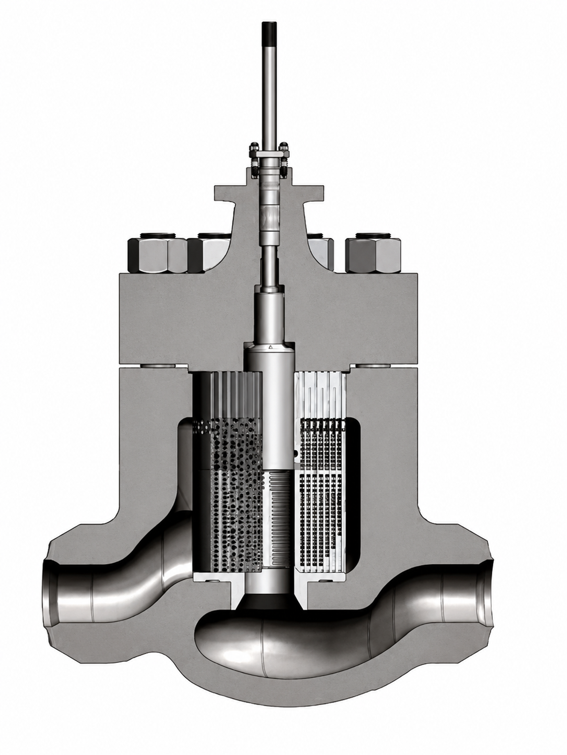
Figure 35. Cross-sectional view of the severe-service recirculation control valve trim and body.
Minimum-recirculation valves must pass the protective flow reliably when main-process demand is low. They may remain closed for long periods and then open against maximum pump head. Seat protection, rapid but stable actuation, debris tolerance, and vibration resistance are therefore critical. Startup-feed valves require high rangeability because pressure drop is high at low flow and decreases as boiler pressure rises. Spray-water valves require precise low-lift control without allowing the seat to become the principal throttling edge. [6-10, 15]
7.5 Oil, Gas, and Petrochemical Service
High-pressure liquid letdown, produced-water injection, wellhead injection, hydrocarbon recycle, pump bypass, and chemical injection can combine cavitation with sand, corrosion, gas breakout, viscosity effects, and remote installation. Refined hydrocarbons can exhibit damage potential comparable with water, whereas crude oils can respond differently because of multicomponent composition and particulate content. Vendor testing and material compatibility are essential. [10, 15]
Large-passage axial trims, dirty-service cages, and hardened or carbide components are commonly used in these services. Compact fine-passage disk stacks can be suitable for clean refined liquids but may plug in crude oil or produced water. The body geometry should direct the outlet jet away from the wall and provide adequate gallery volume. [9, 10, 15]
7.6 Chemical Injection and Very-Low-Flow Service
Very-low-flow-coefficient service is difficult because the controlling openings are small, contamination-sensitive, and exposed to a large fraction of the total pressure drop. MicroCav and low-coefficient ChannelStream trims place multistage grooves or cylinders in a closely guided plug head. Numbered cascade trims provide small repeatable coefficients through labyrinth grooves. Filtration, flushing, material compatibility, and a realistic minimum-flow specification are essential. [1, 2, 8]
7.7 Noise, Vibration, and Actuator Selection
A noise specification should identify the measurement location, operating case, pipe schedule, insulation, and whether the limit applies to predicted airborne sound, internal sound, or workplace exposure. A low external sound level does not demonstrate the absence of cavitation damage. Actuator sizing should include unbalanced hydraulic force, seal friction, packing, acceleration, fail action, and an adequate stability margin. Digital positioners can improve control resolution but cannot compensate for a mechanically unstable plug or an undersized actuator. [9, 10, 15, 20]
8. Worked Sizing and Staging Example
The following example provides a transparent preliminary calculation. It is not a substitute for manufacturer selection because the final coefficients depend on the exact trim geometry and valve travel.
Service: water at 80 °C, m³/h, bar absolute, bar absolute, bar absolute, bar absolute, relative density .
8.1 Operating Severity
The low Sigma value and high operating pressure ratio indicate severe service. A conventional single-stage globe trim is therefore unsuitable as an initial design basis. [1-3, 13-18]
8.2 Choked Pressure Drop and Preliminary Capacity
Assume a conventional globe valve coefficient only to demonstrate the calculation.
The actual pressure drop is 45 bar; therefore, the allowable pressure drop used for this preliminary capacity estimate is 40.14 bar.
A severe service trim with close to unity may pass more flow than this conventional assumption, but the final , body size, and trim must come from the selected vendor geometry. [13, 17, 18]
8.3 Idealized Stage Count
Assume that an individual stage can operate with . Equation (18) gives
The mathematical minimum is seven identical ideal stages. A design margin can be introduced by limiting each stage to , which gives approximately eight stages. The pressure sequence for eight stages is shown in Figure 13. Real stages may have different coefficients, and incomplete recovery can reduce or increase the required count depending on geometry. [3, 7, 9, 10, 17, 18]
8.4 Hydraulic Power
The valve converts hydraulic power into heat, turbulence, vibration, and acoustic energy. The approximate rate is
Using m³/s and MPa,
This result illustrates the importance of hydraulic geometry and mechanical stiffness. Although only a small fraction of the total power becomes airborne sound or damaging impact energy, the overall energy throughput is large. The trim must distribute this energy among many passages and over sufficient material volume. [1-3, 9, 10, 15]
8.5 Selection Implications for the Example
For clean water, candidate architectures include an axial trim with at least eight stages, a multistage multipath cage, a high-capacity disk stack, or a properly staged concentric-sleeve trim. If the water contains large debris, a dirty-service or large-passage axial design is more appropriate even when a larger body is required. The manufacturer should verify every flow case, stage pressure profile, outlet velocity, noise, actuator force, and shutoff condition. An opposed-jet cage is appropriate only when tested data demonstrate that controlled collapse, rather than complete cavitation suppression, provides adequate service life. [1, 2, 7, 9-12, 15]
9. Diagnostics, Monitoring, and Maintenance
9.1 Diagnostic Sequence
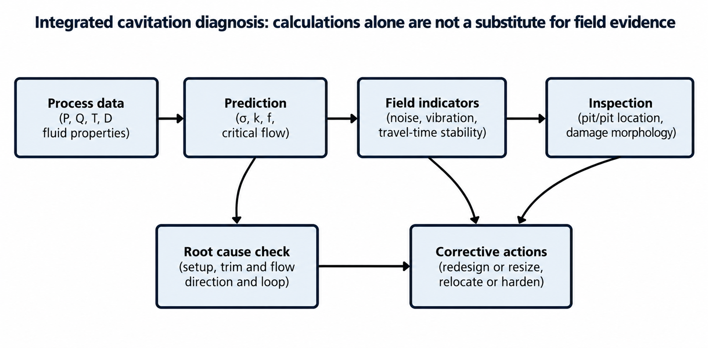
Figure 36. Integrated diagnostic sequence for a suspected cavitation problem.
Diagnosis should begin by reconstructing the actual operating point from calibrated upstream and downstream absolute pressures, fluid temperature, flow rate, and valve position. The operating pressure ratio should then be compared with the tested coefficient at the corresponding travel. Trends in noise, vibration, actuator motion, and process stability should be examined, followed by inspection of the trim and downstream pipe to determine the location and morphology of damage. [2, 3, 14, 15]
9.2 Useful Measurements
| Measurement | Value | Limitation |
|---|---|---|
| Upstream and downstream pressure | Confirms actual pressure ratio and transients | Slow transmitters can miss short surges. |
| Temperature | Establishes vapor pressure | A remote temperature may not represent the valve inlet. |
| Valve travel and command | Identifies low travel severe cases and instability | Position feedback may not show plug vibration. |
| Accelerometers | Detect structural response and changes over time | Resonance can amplify or mask the source. |
| Acoustic emission or high frequency pressure | Sensitive to incipient collapse events | Requires a baseline and careful sensor mounting. |
| Airborne sound | Useful for exposure and gross severity | Damage can occur without extreme airborne sound. |
| Inspection and replicas | Confirms damage location and morphology | Requires outage or removable trim access. |
Table 3. Measurements for cavitation diagnosis.
9.3 Damage Interpretation
Pitting downstream of the seat, especially on the body floor or plug flank, is consistent with a pressure-recovery region that reaches a solid boundary. Symmetric damage around a perforated cage suggests an intense but circumferentially distributed cavity field. One-sided erosion can indicate inlet asymmetry, misalignment, guide damage, an elbow located too close to the valve, or partial blockage. Wire drawing across the seat indicates leakage or throttling at the shutoff edge. [1-3, 10, 12, 15]
Corrosion pitting tends to occur in stagnant or crevice regions, whereas cavitation erosion is associated with high velocity and pressure recovery. Where damage mechanisms overlap, interpretation should include metallography, deposits, fluid chemistry, and operating history. Replacing damaged trim with the same material without correcting the hydraulic pressure profile commonly reproduces the failure. [2, 3, 15]
9.4 Maintenance Strategy
Maintenance should include inspection of all stage passages, dimensional verification of plug and cage clearances, stem straightness, guide wear, seat contact, balance seals, hardfacing condition, and evidence of fretting. Fine-passage trims require flushing and cleanliness control during commissioning. Spare trim should be stored with verified stage and hole patterns because visually similar cages can have different flow coefficients. [1, 2, 5, 9-12, 15]
Trend-based maintenance is preferable to waiting for leakage or gross failure. A rising vibration signature, increasing actuator activity, or a change in acoustic spectrum at the same process point can indicate erosion, blockage, or loss of guidance. Digital valve diagnostics can identify friction and positioning changes, but these data should be interpreted together with process pressure and flow measurements. [10, 15]
10. Patents, Computational Design, and Emerging Directions
10.1 Selected Patent Development
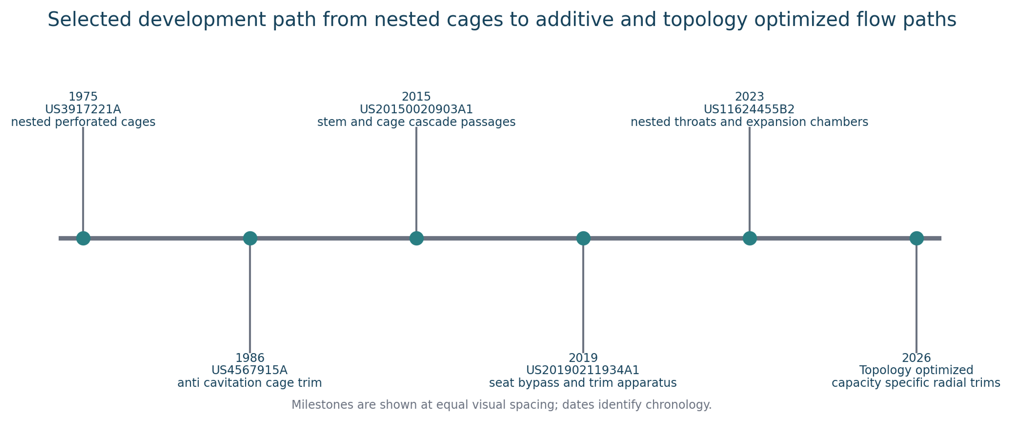
Figure 37. Selected anti-cavitation trim development from nested cages to optimized flow networks.
US3917221A describes a high-pressure-drop valve with multiple nested perforated cages that divide pressure reduction among several stages. US4567915A develops an anti-cavitation, low-noise cage trim for high pressure reduction. US20150020903A1 forms cascade passages jointly in a moving stem and surrounding cage so that different multistage columns open and close with stroke. US20190211934A1 addresses cage and seat arrangements that can maintain a flow path for minimum-flow or noise-reduction functions. US11624455B2 uses parallel passages containing throats and expansion chambers in a compact nested arrangement. [26-30]
Recurring inventive themes include multiplication of pressure-reduction stages, compact passage packing, increased wetted perimeter, controlled expansion, protected seats, debris management, and maintenance of the required flow characteristic over valve travel. These themes are consistent with the manufacturer architectures discussed above. Patent literature also illustrates how additive manufacturing can enable internal passages that are difficult to produce by conventional machining. [25-30]
10.2 CFD and Cavitation Models
Research on sleeve and multistage control valves commonly uses Reynolds-averaged or scale-resolving turbulence models coupled with homogeneous-mixture cavitation models. Qiu and coauthors analyzed pressure drop and cavitation in a sleeve regulating valve. Li and coauthors compared cavitation-modeling approaches and showed how cage design can confine the cavity region. Sun and coauthors investigated flow characteristics in a high-parameter multistage sleeve valve. These studies show that predictions are sensitive to turbulence treatment, nucleation parameters, mesh resolution, pressure boundary conditions, and the selected mass-transfer model. [22-24]
CFD is particularly useful for comparing geometries, locating low-pressure cores, estimating the distribution of pressure drop among stages, and determining whether high-velocity jets impinge on solid surfaces. Predictions should be validated against capacity, pressure, noise, visualization, or erosion data. A smooth mean-pressure field does not by itself demonstrate the absence of instantaneous local cavitation. [15, 22-24]
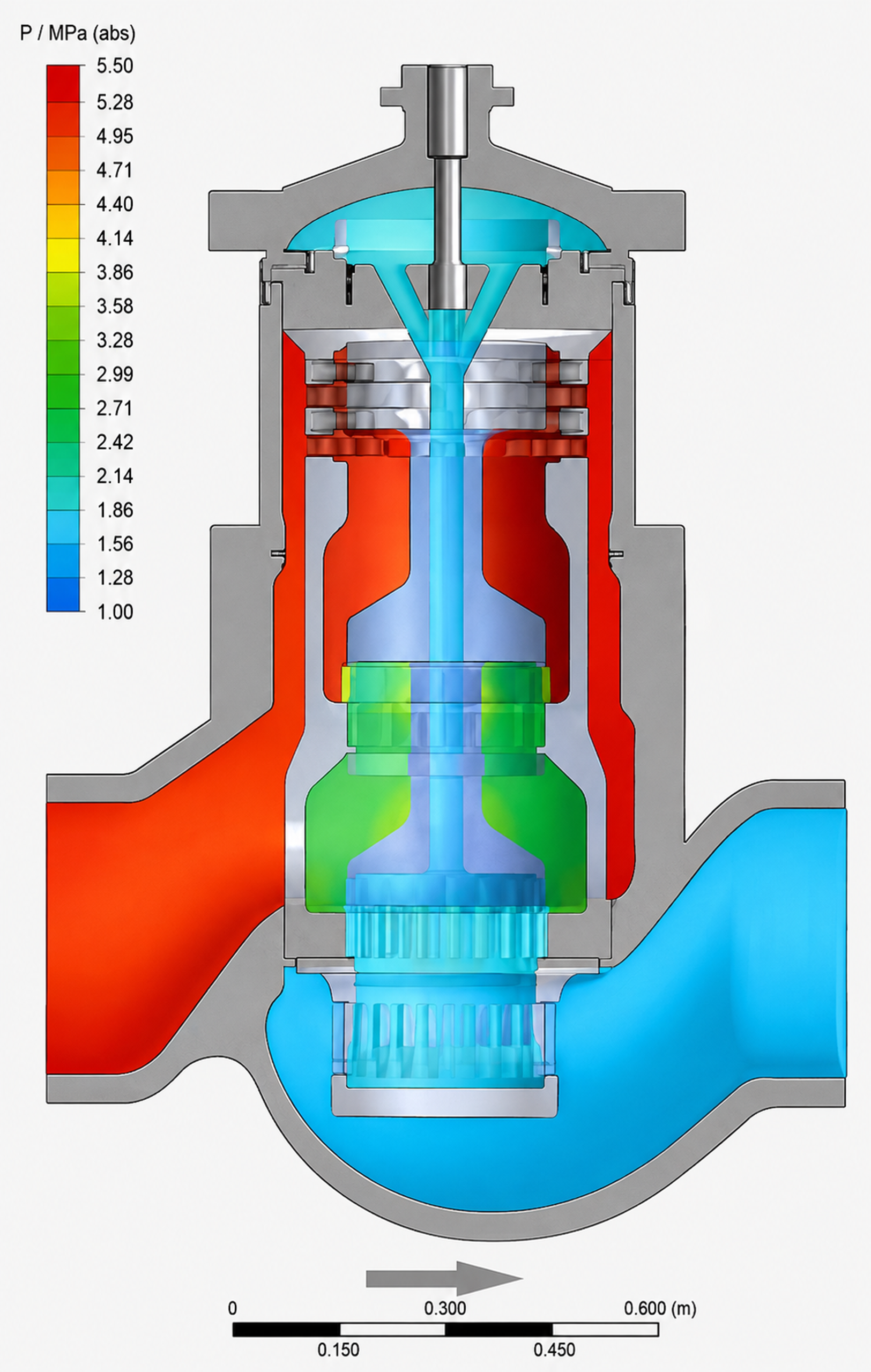
Figure 38. Pressure distribution through Fisher Dirty Service Trim in a NPS 16 easy-e™ valve body.
10.3 Topology Optimization and Additive Manufacturing
Butler, Alexandersen, and Rao presented a density-based topology-optimization framework for capacity-specific radial anti-cavitation trims. Material distribution within a design domain is treated as an optimization variable to obtain a manufacturable flow network with the target capacity while distributing hydraulic losses. This approach can reduce dependence on repeated standard hole patterns and enable passages tailored to a specific operating envelope. [25]
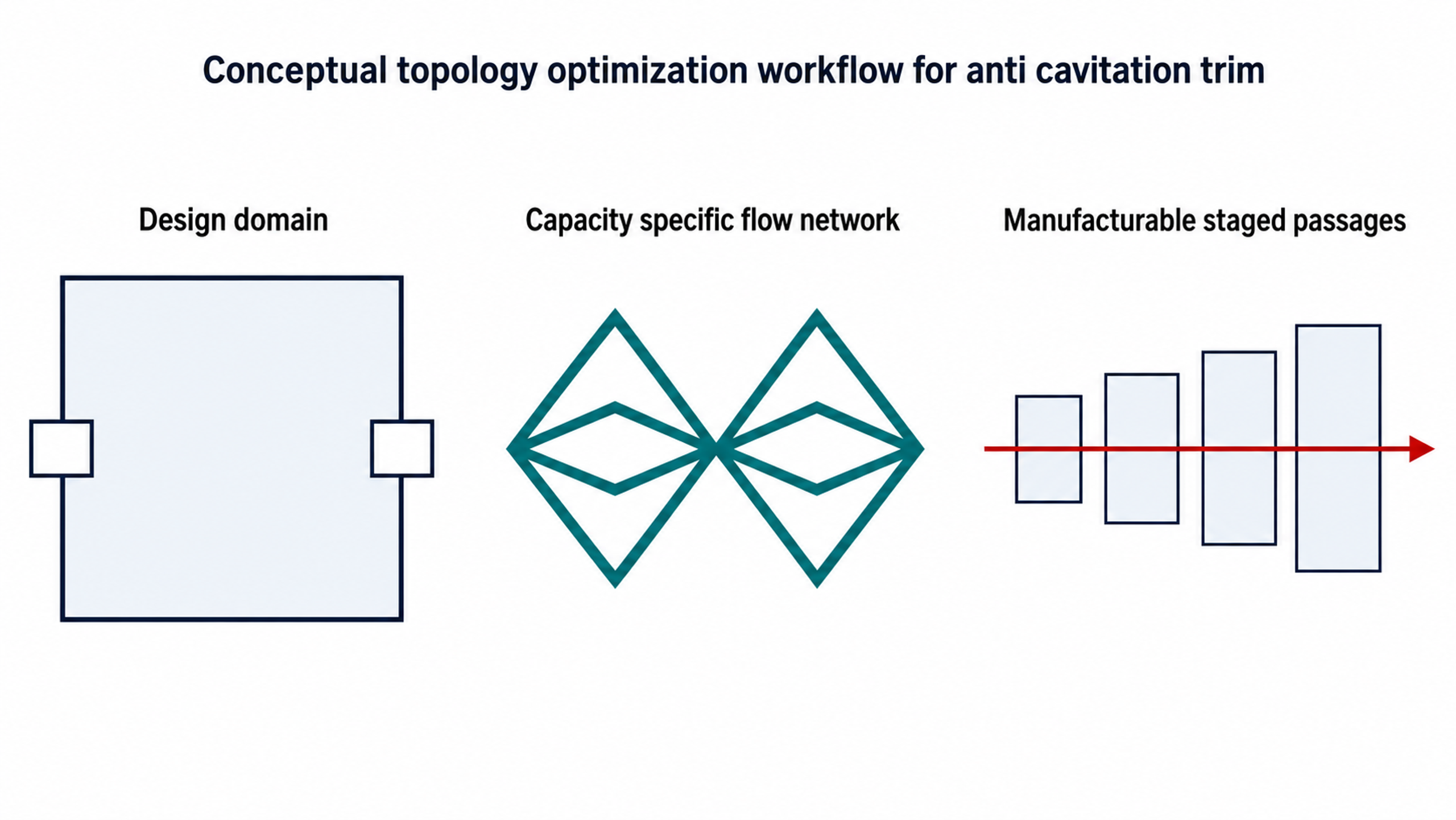
Figure 39. Conceptual workflow from design domain to an optimized staged flow network.
Additive manufacturing expands geometric freedom but introduces additional qualification requirements, including surface roughness, internal powder removal, minimum-passage inspection, dimensional tolerance, anisotropy, residual stress, heat treatment, repairability, and repeatable flow testing. A hydraulically advantageous flow path is useful only if it can be manufactured, cleaned, inspected, and reproduced reliably. [25, 28, 30]
11. Specification and Procurement Guidance
11.1 Functional Specification
A procurement specification should define required performance rather than prescribe a proprietary geometry unless interchangeability is necessary. It should include the complete operating matrix, fluid and solids data, required flow coefficient at each operating case, allowable cavitation regime, required service life, noise target, outlet-velocity limit, shutoff class, flow characteristic, direction of flow, actuator fail action, materials, pressure class, temperature, inspection requirements, documentation, and spare parts. [5, 9, 10, 13, 15-20]
| Item | Recommended requirement |
|---|---|
| Hydraulic calculation | Vendor calculation for every operating case using tested coefficients at the applicable travel. |
| Cavitation assessment | State whether the design eliminates cavitation or controls damage, and identify the limiting coefficient and margin. |
| Stage profile | Provide stage count and a pressure or pressure ratio allocation for severe service. |
| Velocity | Provide trim, gallery, and outlet velocities at maximum and severe low flow cases. |
| Solids | State minimum passage size and maximum allowable particle. |
| Materials | Identify base material, heat treatment, hardfacing, hardness range, and corrosion compatibility. |
| Seat protection | Describe how throttling is separated from shutoff at low lift. |
| Noise and vibration | Provide prediction method, operating case, measurement location, and guarantee basis. |
| Testing | Capacity, seat leakage, hydrostatic, functional, and any cavitation or noise demonstration required. |
| Documentation | Certified drawings, trim identification, coefficient curves, materials, maintenance instructions, and spare parts list. |
Table 4. Recommended procurement requirements.
11.2 Bid Evaluation Questions
-
Is the quoted coefficient based on the exact trim, travel, and flow direction?
-
Does the design eliminate cavitation or only relocate collapse?
-
What is the limiting operating case, and what margin is provided?
-
Are all stages active at low travel?
-
What is the minimum passage and credible particle size?
-
Where is the final pressure recovery expected to occur?
-
Are the seat and shutoff surfaces protected from the controlling jet?
-
What materials and heat treatments are used in each trim component?
-
What field experience exists at comparable absolute pressure, size, and fluid?
-
Can the trim be inspected, cleaned, repaired, and reproduced?
These questions discourage selection based only on nominal body size, a single , or an unscaled cavitation coefficient. [1-3, 5, 9, 10, 13-18]
12. Conclusions
Anti-cavitation control valves function by managing the pressure and velocity history of the liquid through the entire pressure-reduction process. The central design objective is to prevent a single local restriction from producing an uncontrolled pressure minimum followed by strong recovery near a vulnerable surface. This objective can be achieved through staged pressure reduction, flow subdivision, progressive area increase, frictional dissipation, impingement, tortuous passages, protected seats, enlarged galleries, and appropriate system layout. [1-15]
The principal engineering conclusions are as follows:
-
Cavitation is governed by local instantaneous pressure, nuclei, residence time, and pressure recovery, not only by the overall pressure drop.
-
Flashing and liquid choking must be identified separately because their flow and damage mechanisms differ.
-
Sigma, , , , , and are useful only when their definitions, pressure locations, travel, and vendor test basis are consistent.
-
Severe service usually requires multistage pressure reduction. Stage resistance should be allocated to keep later stage velocity and pressure excursions under control.
-
Opposed jets can protect trim in mild service by moving collapse into the fluid core, but they do not necessarily eliminate cavitation.
-
Seat protection, strong guidance, actuator stiffness, and body gallery design are as important as the nominal number of stages.
-
Fine passages are compact and effective for clean service. Dirty service requires large continuous passages, protected seats, and credible particle data.
-
Hardened materials extend life but cannot compensate for a fundamentally incorrect pressure profile.
-
Final selection requires all operating cases, installed piping effects, tested vendor coefficients, scale effects, noise and vibration assessment, and maintainability.
-
CFD, additive manufacturing, and topology optimization can improve capacity-specific trim designs, but these methods require experimental validation and manufacturing qualification. [1-32]
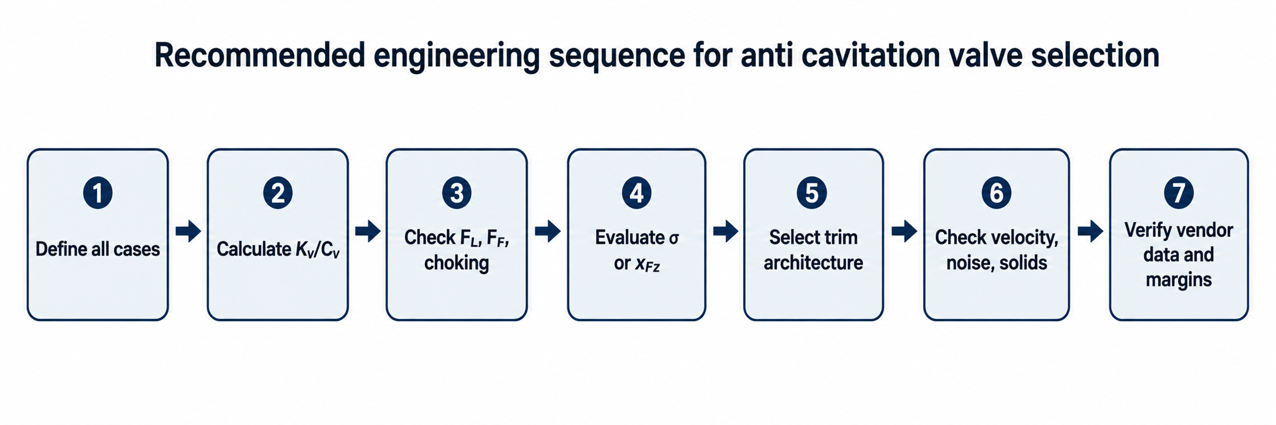
Figure 40. Recommended engineering sequence from process definition to verified selection.
Nomenclature and Greek Letters
| Symbol | Meaning | Typical unit |
|---|---|---|
| A | Flow area | m² |
| Cv | Customary valve flow coefficient | US gal/min at 1 psi for water at reference condition |
| D | Diameter | m or mm |
| Liquid critical pressure ratio factor | dimensionless | |
| Liquid cavitation factor used by a manufacturer sizing method | dimensionless | |
| Liquid pressure recovery factor without attached fittings | dimensionless | |
| Combined liquid pressure recovery and piping geometry factor | dimensionless | |
| Piping geometry factor | dimensionless | |
| G | Gas content constant in the simplified bubble equilibrium relation | pressure times volume |
| g | Gravitational acceleration | m/s² |
| Head loss | m of liquid | |
| Cavitation resistance parameter | method dependent | |
| SI valve flow coefficient | m³/h at 1 bar for water at reference condition | |
| n | Number of pressure reducing stages | dimensionless |
| p | Local absolute pressure | Pa or bar absolute |
| p₁ | Valve upstream absolute pressure | Pa or bar absolute |
| p₂ | Valve downstream absolute pressure | Pa or bar absolute |
| Pressure inside a bubble | Pa | |
| Thermodynamic critical pressure | Pa or bar absolute | |
| Noncondensable gas pressure inside a bubble | Pa | |
| Minimum local pressure in the valve | Pa or bar absolute | |
| Vapor pressure at flowing temperature | Pa or bar absolute | |
| Hydraulic power dissipated | W | |
| Q | Volumetric flow rate | m³/s or m³/h |
| R | Bubble radius | m |
| Maximum bubble radius | m | |
| SSE | Size scale effect | dimensionless |
| PSE | Pressure scale effect | dimensionless |
| Approximate bubble collapse time | s | |
| Deformation energy to fracture per unit volume | J/m³ | |
| v | Mean velocity | m/s |
| Operating liquid pressure ratio | dimensionless | |
| Valve specific incipient cavitation coefficient | dimensionless | |
| z | Elevation | m |
| Δp | Pressure difference | Pa or bar |
| γ | Surface tension, also used in some literature for a normalized bubble wall distance | N/m or dimensionless, according to context |
| μ | Dynamic viscosity | Pa s |
| ν | Kinematic viscosity | m²/s |
| ρ | Fluid density | kg/m³ |
| Relative density or specific gravity | dimensionless | |
| σ | Cavitation index (p₁ − )/(p₁ − p₂) | dimensionless |
| Reference cavitation index | dimensionless | |
| Scale corrected cavitation index | dimensionless | |
| Ṙ, R̈ | First and second time derivatives of bubble radius | m/s and m/s² |
Table 5. Symbols and Greek letters used in the article.
Greek letter explanations: denotes surface tension in the bubble equations. is dynamic viscosity. is kinematic viscosity. is density. is the cavitation index. The dot notation over denotes differentiation with respect to time.
Bibliography
[1] Flowserve Corporation. Valtek Severe Service Equipment. Valtek Control Products, technical bulletin, n.d.
[2] Flowserve Corporation. Flowserve Cavitation Control. Product and application bulletin FCENBR0068, n.d.
[3] SAMSON AG. Cavitation in Control Valves. Technical Information, Part 3, L351 EN. Frankfurt: SAMSON AG; 2011.
[4] Ross Valve Manufacturing Co. Anti Cavitation Solutions: WaterTamer Valve and Energy Dissipators. Troy, NY: Ross Valve Manufacturing Co.; 2007.
[5] Singer Valve. Model 106 / 206 AC Anti Cavitation Control Valve. Product catalog FC09-10; 2010.
[6] Copes Vulcan, SPX Flow Control. Cascade and Super Cascade Trims. Bulletin CV-101; 2008.
[7] Valvitalia. LTG6 Multistage Single Path Cascade Trim Control Valves. Revision 2; n.d.
[8] Copes Vulcan, SPX Flow Technology. Numbered Cascade Trim. Bulletin CV-135-US; 2012.
[9] MIL Controls Limited. MIL 91000 Matrix Series: Extreme Pressure and High Pressure Drop Control Valves with Multistage, Multipath Trim. 2014.
[10] Dresser Masoneilan. LincolnLog 78400 / 18400 Series High Pressure Anti Cavitation Control Valves. Bulletin BP78400; 2008.
[11] Singer Valve. Anti Cavitation Trim: Model 106 AC Automatic Control Valve. Product brochure; n.d.
[12] Mascot Valves. CavFlo Cavitation Control Trim. Ahmedabad, India: Mascot Valves; n.d.
[13] Valtek. Control Valve Sizing. Sizing and Selection, Section 3, Revision 6/94.
[14] Parish J. Controlling Cavitation: How a Deeper Understanding Improves the Solution. Valve Magazine. Summer 2009:1-5.
[15] Emerson Process Management, Fisher. Fisher Cavitation Control Technologies: Solutions to Cavitation Problems. Product and application bulletin D351912X012; n.d.
[16] International Society of Automation. ISA-RP75.23-1995 (R2024): Considerations for Evaluating Control Valve Cavitation. Research Triangle Park, NC: ISA; reaffirmed 2024.
[17] International Electrotechnical Commission. IEC 60534-2-1:2011, Industrial Process Control Valves, Part 2-1: Flow Capacity, Sizing Equations for Fluid Flow under Installed Conditions. Geneva: IEC; 2011. Corrigendum 1; 2015.
[18] International Electrotechnical Commission. IEC 60534-2-3:2015, Industrial Process Control Valves, Part 2-3: Flow Capacity, Test Procedures. Geneva: IEC; 2015.
[19] International Electrotechnical Commission. IEC 60534-8-2:2011, Industrial Process Control Valves, Part 8-2: Noise Considerations, Laboratory Measurement of Noise Generated by Hydrodynamic Flow through Control Valves. Geneva: IEC; 2011.
[20] International Electrotechnical Commission. IEC 60534-8-4:2015, Industrial Process Control Valves, Part 8-4: Noise Considerations, Prediction of Noise Generated by Hydrodynamic Flow. Geneva: IEC; 2015.
[21] Brennen CE. Cavitation and Bubble Dynamics. New York: Oxford University Press; 1995. Open author version available through CaltechAUTHORS.
[22] Qiu C, Jiang CH, Zhang H, Wu JY, Jin ZJ. Pressure Drop and Cavitation Analysis on Sleeve Regulating Valve. Processes. 2019;7(11):829. doi:10.3390/pr7110829.
[23] Li J, Gao ZX, Wu H, Jin ZJ. Numerical Investigation of Methodologies for Cavitation Suppression Inside Globe Valves. Applied Sciences. 2020;10(16):5541. doi:10.3390/app10165541.
[24] Sun Y, Wu J, Xu B, Bai Y. Flow Characteristics Study of High Parameter Multistage Sleeve Control Valve. Processes. 2022;10(8):1504. doi:10.3390/pr10081504.
[25] Butler B, Alexandersen J, Rao P. Capacity Specific Anti Cavitation Radial Control Valve Trims via Density Based Topology Optimization. Fluids. 2026;11(6):153. doi:10.3390/fluids11060153.
[26] Kubota, Ltd. High Pressure Drop Valve. US Patent US3917221A. Issued November 4, 1975.
[27] Valtek Incorporated. Anti Cavitation Low Noise Control Valve Cage Trim for High Pressure Reducing Service in Liquid or Gaseous Flow. US Patent US4567915A. Issued February 4, 1986.
[28] Control Components, Inc. Cascade Trim for Control Valve. US Patent Application US20150020903A1. Published January 22, 2015.
[29] Fisher Controls International LLC. Valve Trim Apparatus for Use with Control Valves. US Patent Application US20190211934A1. Published July 11, 2019.
[30] Fisher Controls International LLC. Valve Trim. US Patent US11624455B2. Issued April 11, 2023.
[31] Falvey HT. Cavitation in Chutes and Spillways. Engineering Monograph No. 42. Denver, CO: United States Bureau of Reclamation; 1990.
[32] Rao PV. Size Scale Effect in Cavitation Erosion. NASA Technical Memorandum 83533. Washington, DC: National Aeronautics and Space Administration; 1982.
[33] Kozyuk O. Hydrodynamic Cavitation. [Unpublished technical manuscript and supporting data] 2026.