
Technical publication
Back to publications
Reactors & equipment
Anti-Cavitation Control Valves
okozyuk.com
Published
Read complete publication for whole-document Find and printing. Browser Find and native printing on this reader include only loaded content.
Abstract
Cavitation in liquid control valves results from local pressure reduction below vapor pressure followed by vapor collapse during pressure recovery. The associated microjets, pressure waves, vibration, and unsteady hydraulic forces can cause trim erosion, pressure boundary damage, noise, loss of control authority, and reduced service life. This article presents a unified engineering treatment of cavitation physics, liquid valve sizing parameters, pressure recovery behavior, and anti-cavitation trim architecture. The discussion relates cavitation indices and liquid choking criteria to practical design strategies, including staged pressure reduction, opposed jet bubble isolation, stacked disk and concentric sleeve trims, axial multistage geometries, multipath trims, dirty service configurations, and fixed energy dissipators. Material selection, seat protection, outlet velocity, actuator stability, solids tolerance, and system layout are examined as coupled design variables. Application considerations are summarized for water distribution, power generation, oil and gas, petrochemical, and low flow injection services. A worked sizing example demonstrates preliminary severity assessment, choked flow capacity, stage count estimation, and hydraulic power dissipation. The article also reviews field diagnosis, maintenance, computational fluid dynamics, patent development, topology optimization, and additive manufacturing. Final valve selection should be based on the complete operating envelope and tested coefficients for the specific valve and trim geometry. Keywords: cavitation; control valves; anti-cavitation trim; pressure staging; liquid choking; valve sizing; severe service.
5. Anti-Cavitation Trim Architectures
5.1 Perforated Cages and Opposed-Jet Trims
Perforated-cage trims distribute multiple holes around a cylindrical retainer. Hole diameter and spacing determine capacity and flow characteristic, while opposed pairs provide mutual jet impingement. A closely guided plug progressively uncovers rows of holes as it moves, allowing the cage characteristic to be tailored. These trims are compact and economical for clean liquids, but close plug-to-cage clearances and small holes are susceptible to dirt, scale, weld debris, and galling. [1, 2, 5, 11, 12]
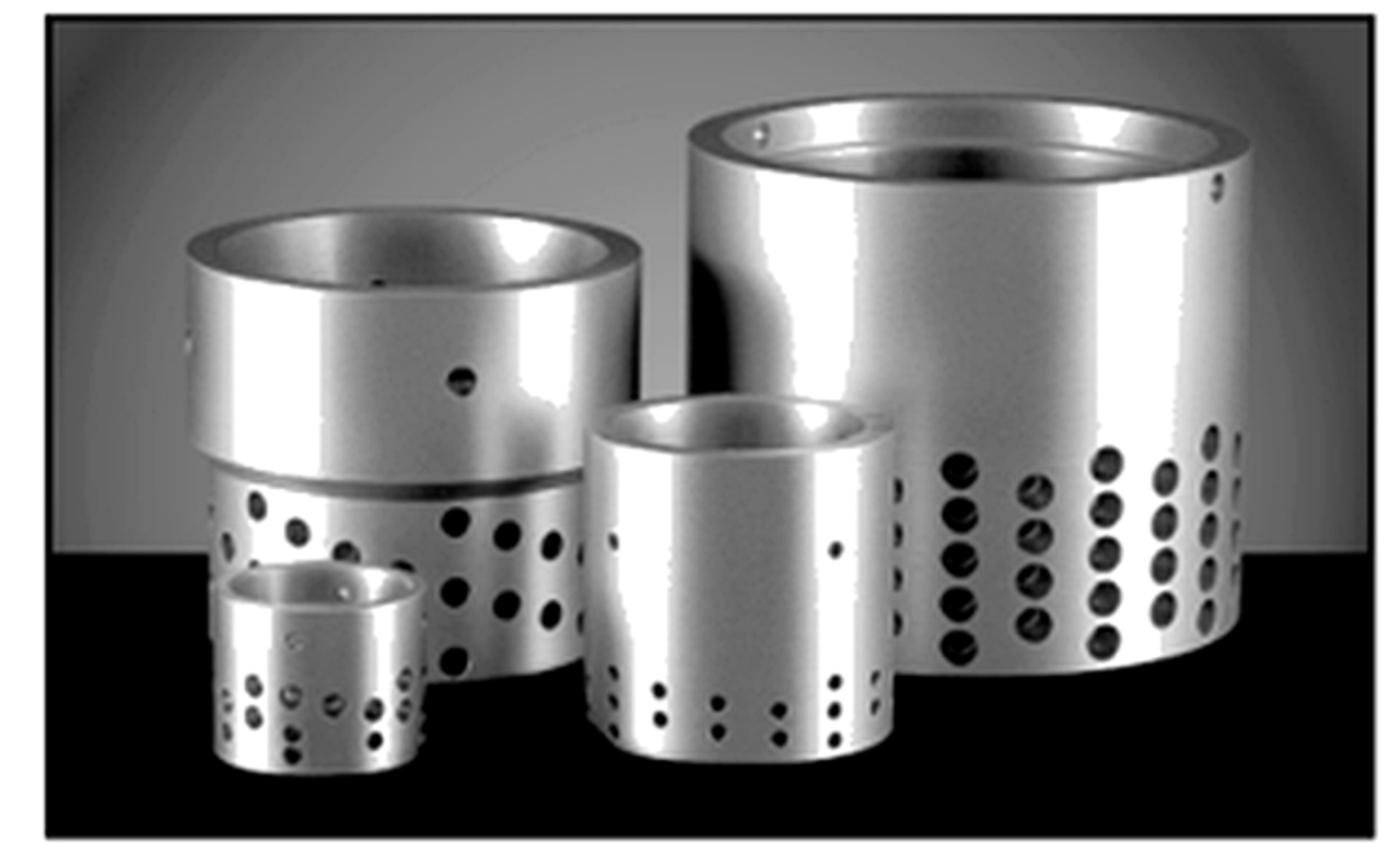
Figure 19. CavControl trim.
CavControl uses multiple small, diametrically opposed flow holes in a special seat retainer (Figure 19). Flow is directed over the plug. As the plug lifts from the seat, successive pairs of holes are uncovered. Each hole produces a cavitating liquid jet that impinges on the opposing jet near the center of the retainer (Figure 20). The resulting interaction creates a central recovery region that promotes vapor collapse away from metal surfaces. Stepped holes are used to favor orifice-type rather than tube-type behavior so that the vena contracta forms outside the retainer passage. [1]
Table 1. CavControl Trim Materials of Construction
| Trim Part | Available Materials |
|---|---|
| Seat Retainer | 316 stainless steel or 400 series hardened stainless steel |
| Plug | 316 stainless steel with Alloy 6 facing or 400 series hardened stainless steel |
| Seat Ring | 316 stainless steel with Alloy 6 facing or 400 series hardened stainless steel |
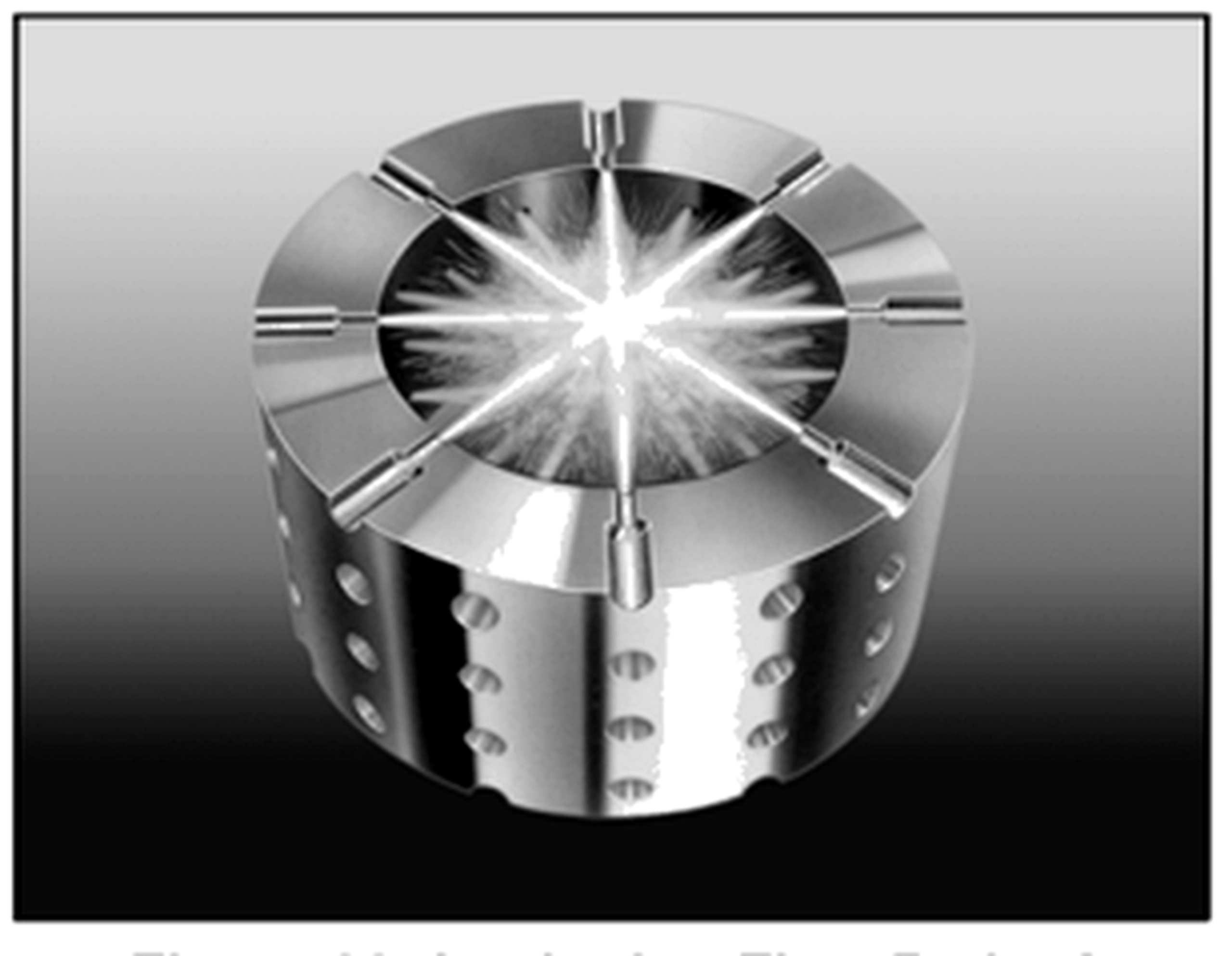
Figure 20. CavControl cage, impinging flow path.
Flow capacity and characteristic are governed by the diameter and spacing of the holes in the seat retainer.
Different hole diameters and spacing patterns can be combined on a single retainer to obtain the required flow characteristic.
Application capacity can be calculated using standard ISA sizing equations. Relative to a conventional globe valve, the CavControl trim is designed for lower pressure recovery and reduced susceptibility to liquid choking, so a given flow coefficient can pass a larger flow at the same pressure drop when the applicable tested coefficients support the calculation. [1]
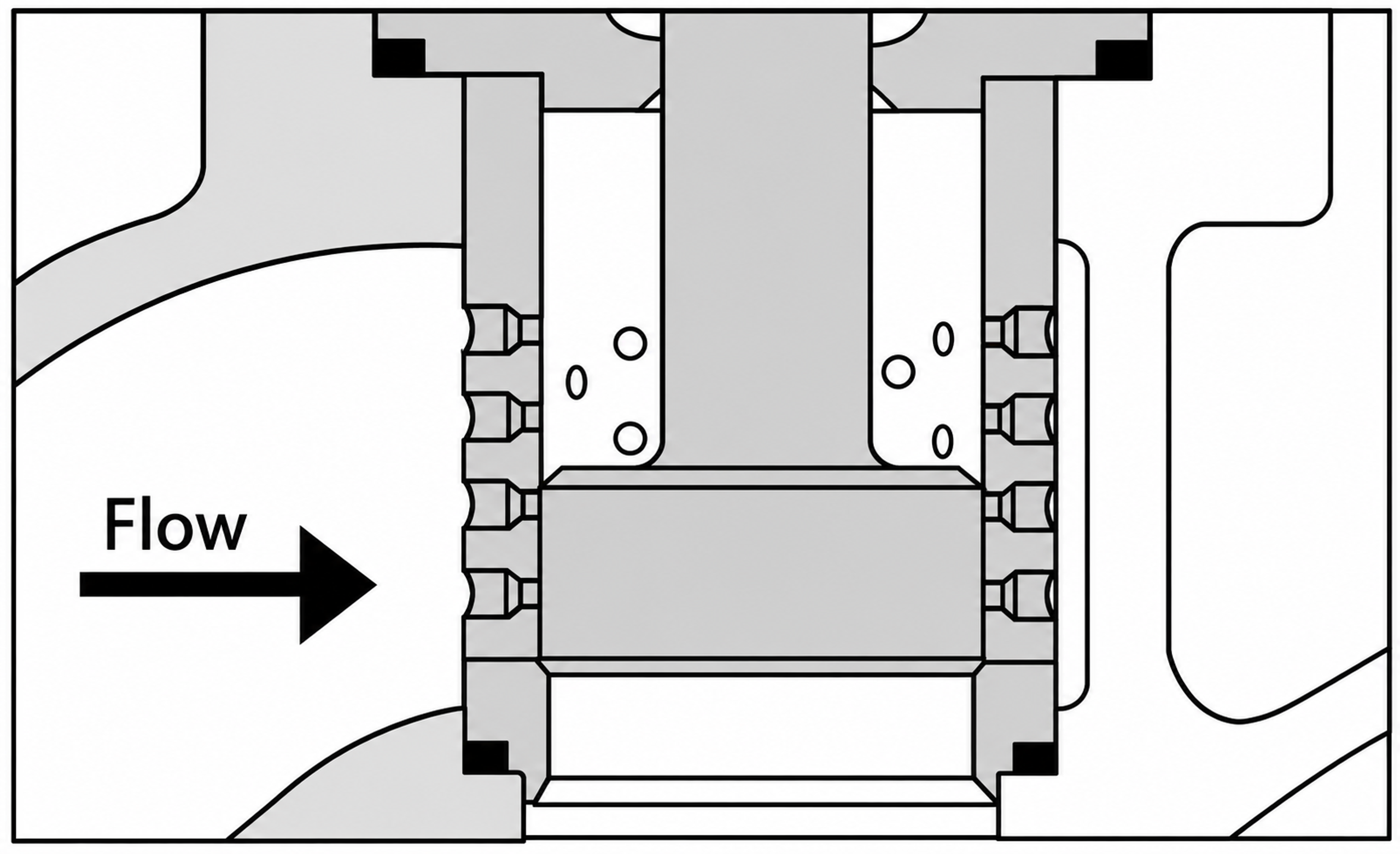
Figure 20. Mascot CavFlo opposed jet trim and pressure profile.
Mascot CavFlo similarly uses multiple small holes for diametrical flow through the seat retainer. As the plug lifts, additional opposed hole pairs are uncovered, and the corresponding cavitating jets impinge near the center of the retainer. [12]
Table 2. Standard Materials of Construction
| Trim Part | Standard Material |
|---|---|
| Seat Retainer | 316 stainless steel or 416 hardened stainless steel |
| Plug | 316 stainless steel with Stellite facing |
| Seat Ring | 316 stainless steel with Stellite facing |
Because the plug closely guides within the retainer while regulating flow through the holes, the fluid must be sufficiently clean to prevent seizure caused by dirt or pipe debris. Hole diameter and spacing determine flow capacity and characteristic. Variable hole sizes and spacing can be combined to obtain the required characteristic. CavFlo is configured for flow over the plug. [12]
5.2 Dual-Cage and Waterworks Valves
Large water-distribution valves may use two sliding perforated sleeves within an automatic valve body. The first cage produces an initial pressure reduction and contains the corresponding recovery region, while the second cage provides additional control toward the downstream pressure. The orifice pattern is selected for the specified inlet-pressure, outlet-pressure, and flow envelope. This arrangement avoids reliance on a fixed downstream orifice whose effectiveness decreases at low flow. [4, 5, 11]
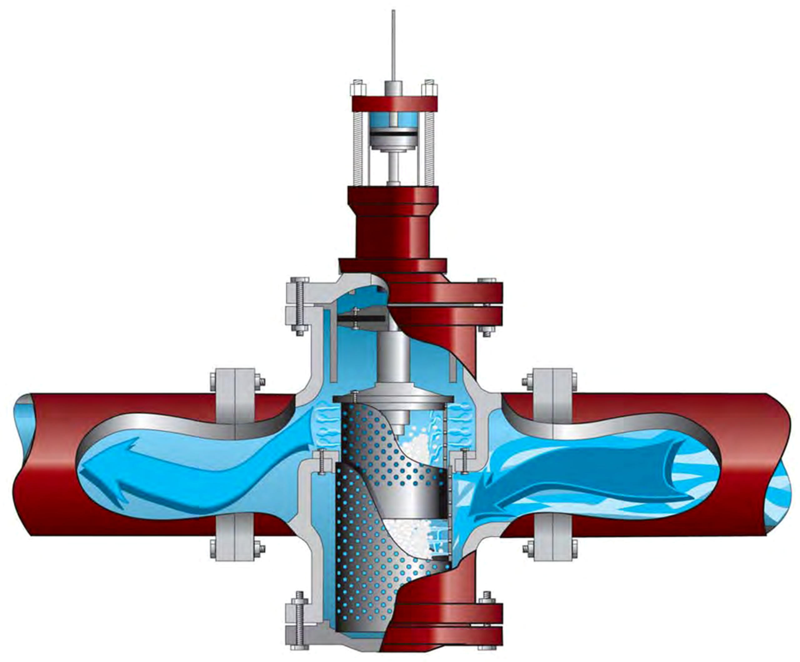
Figure 21. Ross WaterTamer anti-cavitation valve cutaway.
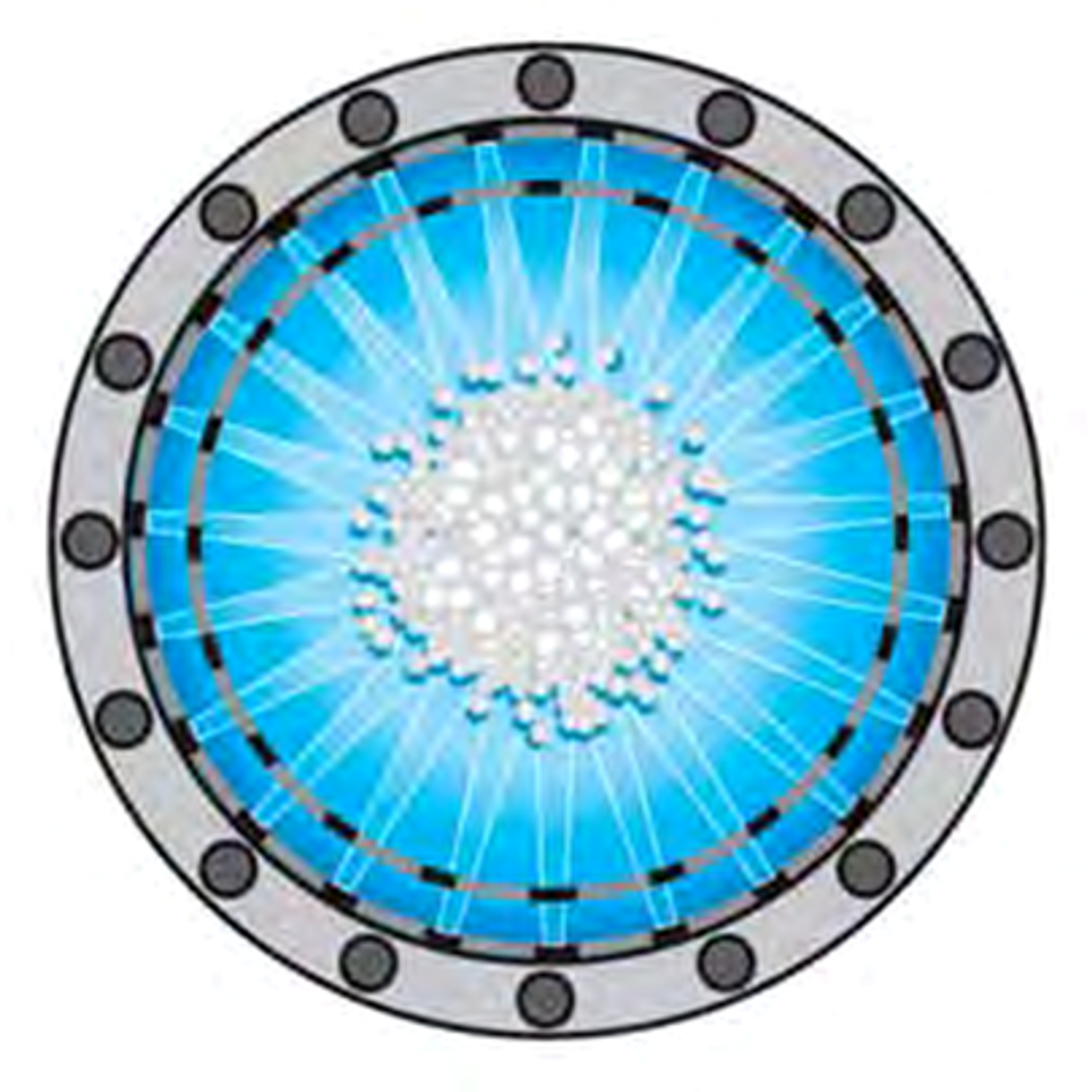
Figure 22. Top view of the WaterTamer nozzle arrangement and central cavitation region.
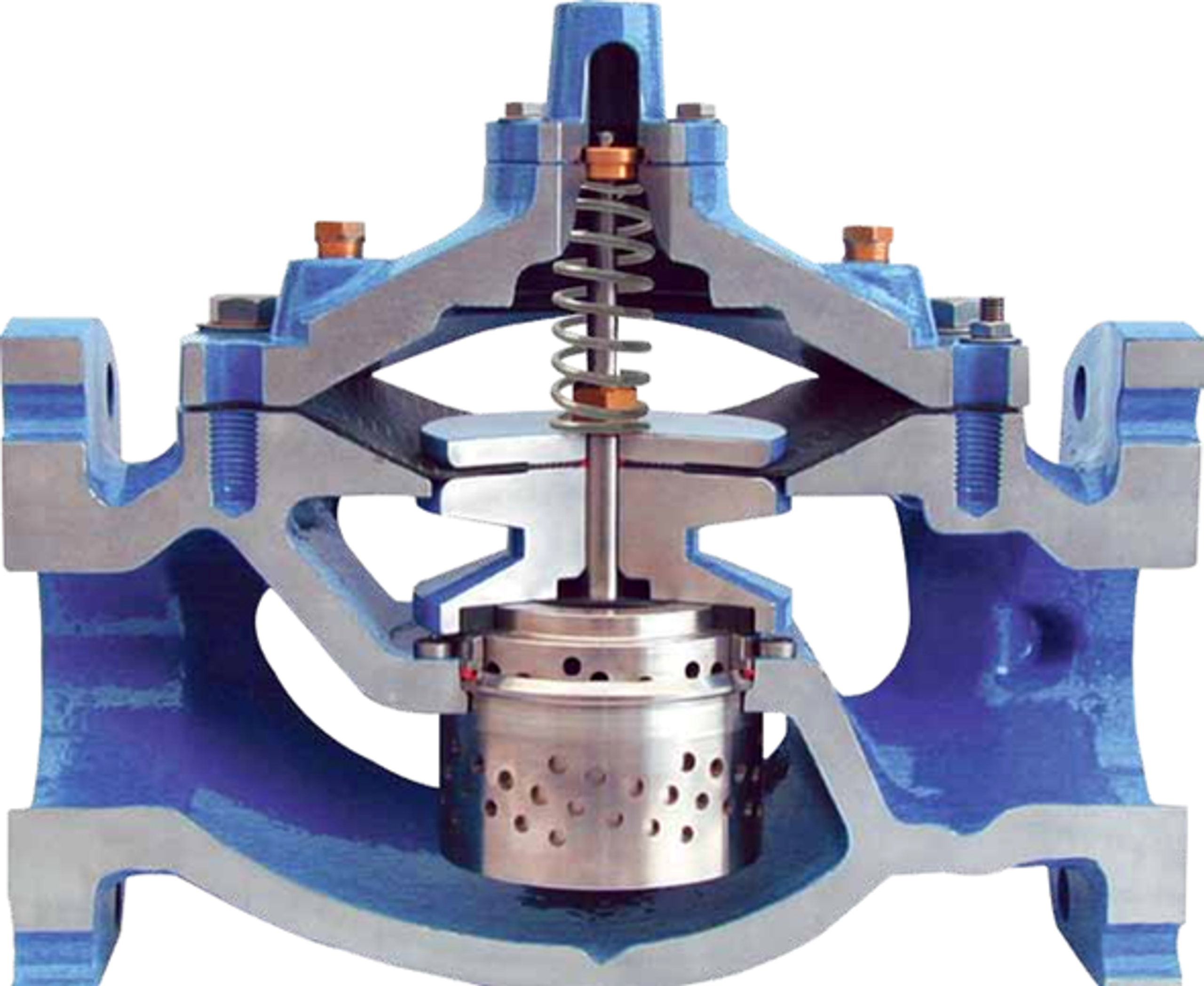
Figure 23. Singer Model 106-PG-AC dual-cage anti-cavitation valve cutaway.
Ross WaterTamer uses inner and outer chambers with opposed nozzles so that the cavity field is concentrated within a central water column. Singer uses dual sliding cages with application-specific round holes. Both approaches show that large waterworks valves require uniform circumferential entry, adequate body clearance, and strong guidance to maintain a symmetric collapse region. [4, 5, 11]
5.3 Stacked-Disk and Expanding-Tooth Trims
Stacked-disk trims create numerous parallel passages within a cylindrical stack. Individual paths may contain teeth, grooves, turns, restrictions, and expansion regions. In the Tiger Tooth design, flow passes radially through a sequence of expanding teeth. Smaller upstream teeth impose a larger fraction of the initial pressure drop, while larger downstream passages limit later-stage velocity and pressure excursions. Disk stacks can be characterized by varying the number, size, and arrangement of flow paths. [1, 2]
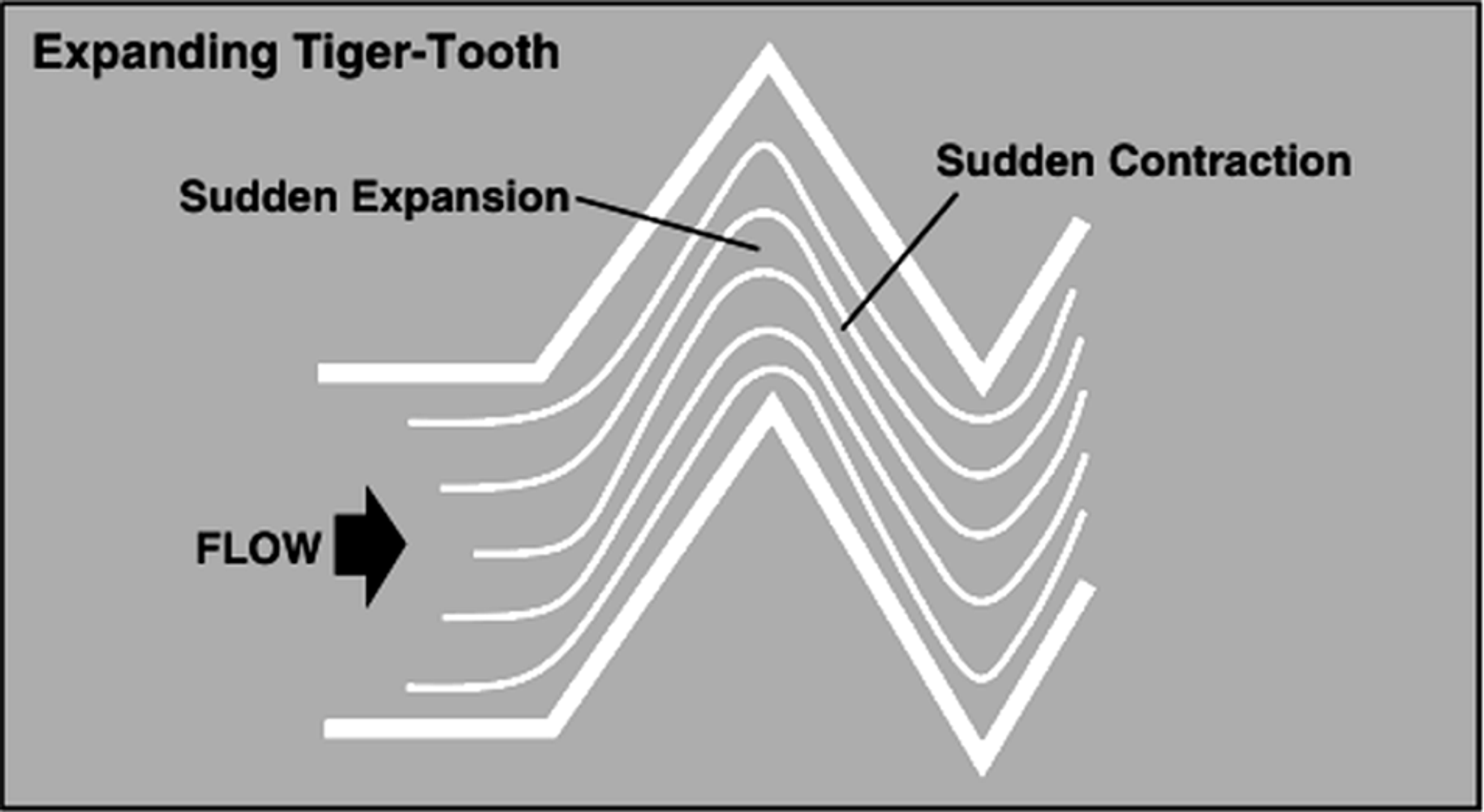
Figure 24: Sudden Expansion and Contraction Caused by Tiger-Tooth Design.
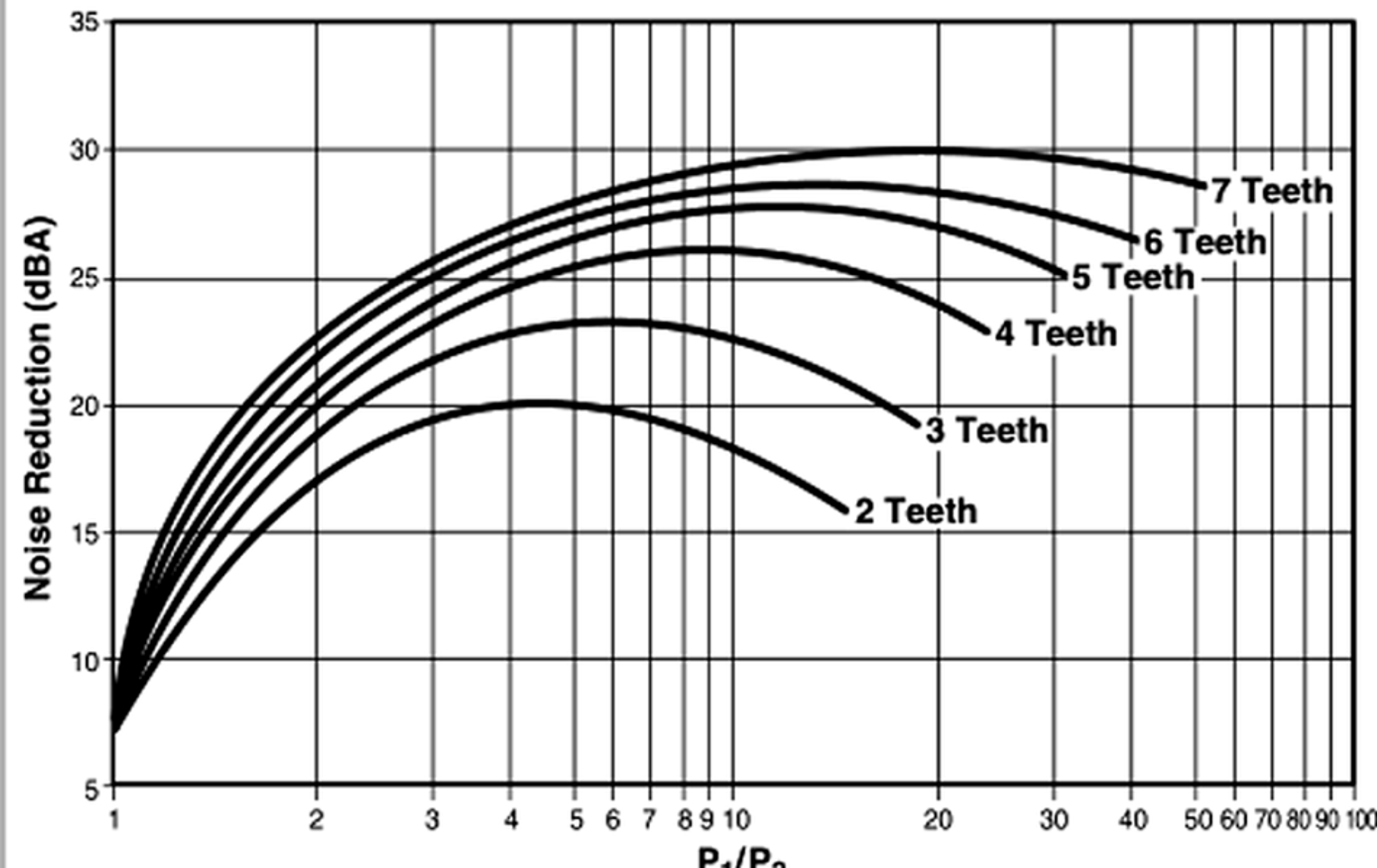
Figure 25: Noise Reduction vs. Number of Tiger-Tooth Teeth.
Table 3: Tiger-Tooth Materials of Construction
| Trim Part | Available Materials |
|---|---|
| Stack | Aluminum-Bronze, 410 stainless steel, 316 stainless steel, 316 stainless steel with Alloy 6 overlay, other alloys as required |
| Plug | 316 stainless steel, 316 stainless steel with Alloy 6 overlay, other alloys as required |
| Seat Ring | 316 stainless steel, 316 stainless steel with Alloy 6 overlay, other alloys as required |
Disk stacks provide high hydraulic resistance within a compact diameter, but narrow passages are susceptible to plugging and must be checked against the maximum credible particle size. Designs with open radial passages and without horizontal ledges are generally more tolerant of contamination than fine labyrinth stacks. Maintenance requires access for passage inspection and verification of stable plug guidance throughout the stroke. [1, 2, 10, 14]
5.4 Intersecting-Channel and Concentric-Sleeve Trims
ChannelStream uses staged cylinders and intersecting channels so that flow repeatedly passes through restrictions, channels, expansion regions, and impingement zones. Low-flow versions place stages in the plug head, permitting very small flow coefficients but requiring exceptionally clean service. Gestra ZK uses concentric perforated sleeves with shifted or partly overlapping openings that form serial nozzles separated by intermediate chambers. The standard ChannelStream trim is intended for flow coefficients of 2.5 Cv and above and uses a cartridge in place of a seat retainer. Flow passes over the plug through a series of close-fitting cylindrical stages containing expansion holes and intersecting circumferential channels (Figures 26 and 27). [1, 2]
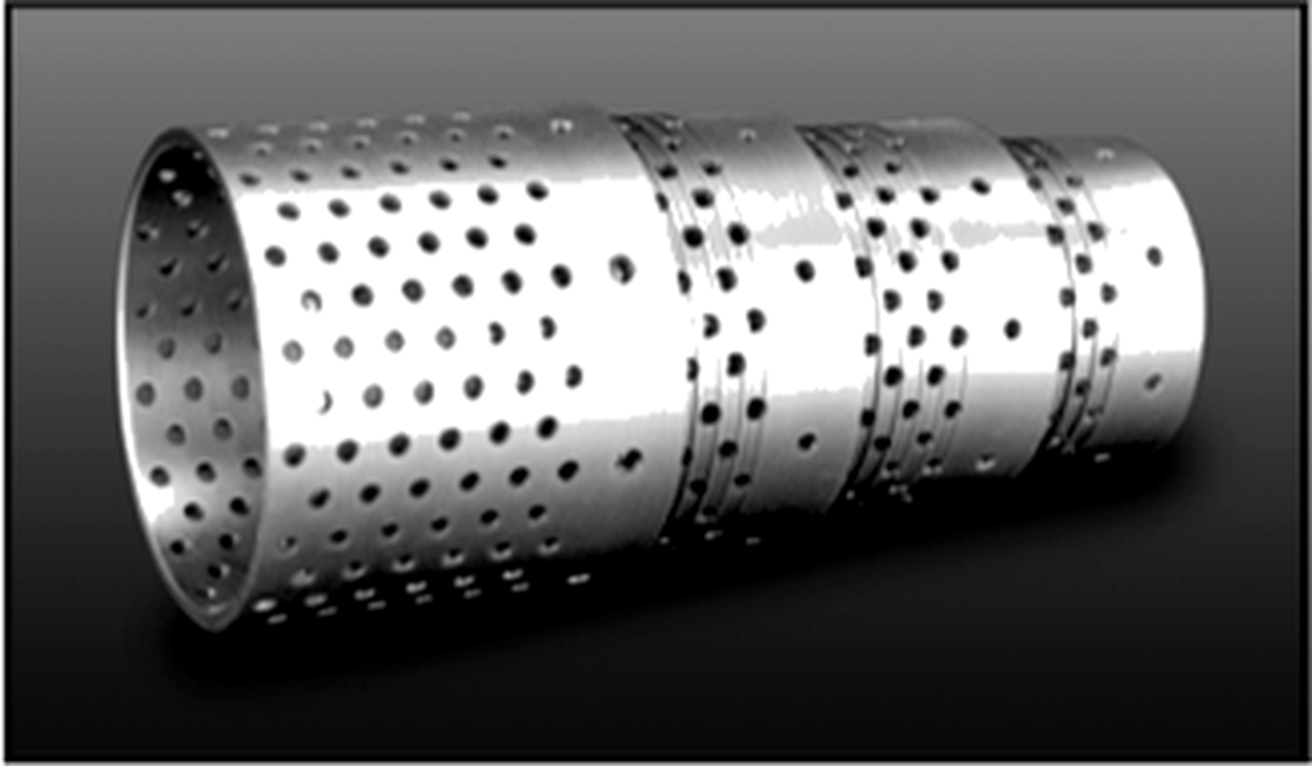
Figure 26. ChannelStream cartridge showing individual stages.
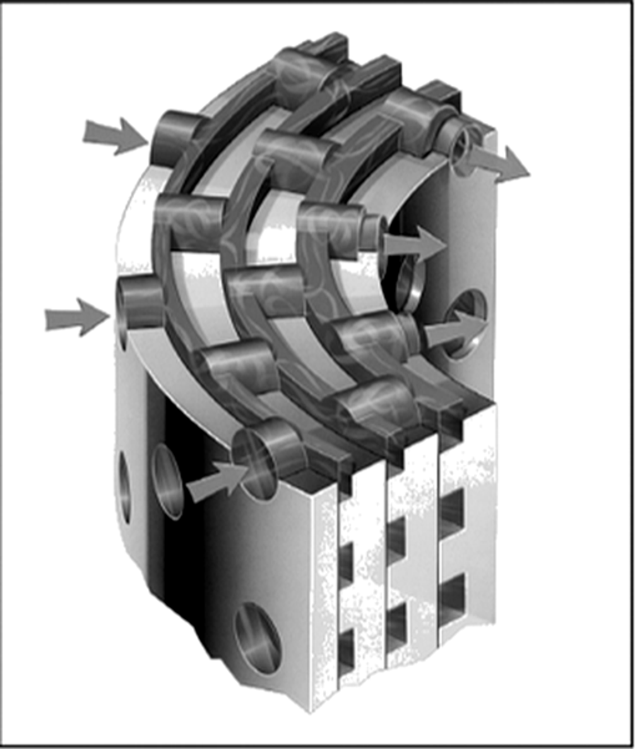
Figure 27. ChannelStream cartridge and three-dimensional flow path.
Concentric-sleeve construction also appears in early patent literature. US3917221A describes nested perforated cylindrical cages for staged pressure reduction. Later patents modify aperture shape, wetted perimeter, and the relationship between throats and expansion chambers to increase hydraulic resistance while preserving capacity. [26, 30]
5.5 Labyrinth and Cascade Trims
Cascade trims machine a sequence of grooves or contoured steps into the plug and cage so that fluid follows a long single path. The total pressure drop is divided among the grooves, limiting pressure recovery at any one location. At low flow, the plug remains close to the seat and the full cascade is active. At higher flow, some designs progressively bypass early grooves as process pressure drop decreases. Super Cascade and top-guided variants retain staged pressure reduction through a larger fraction of travel. [6-8]
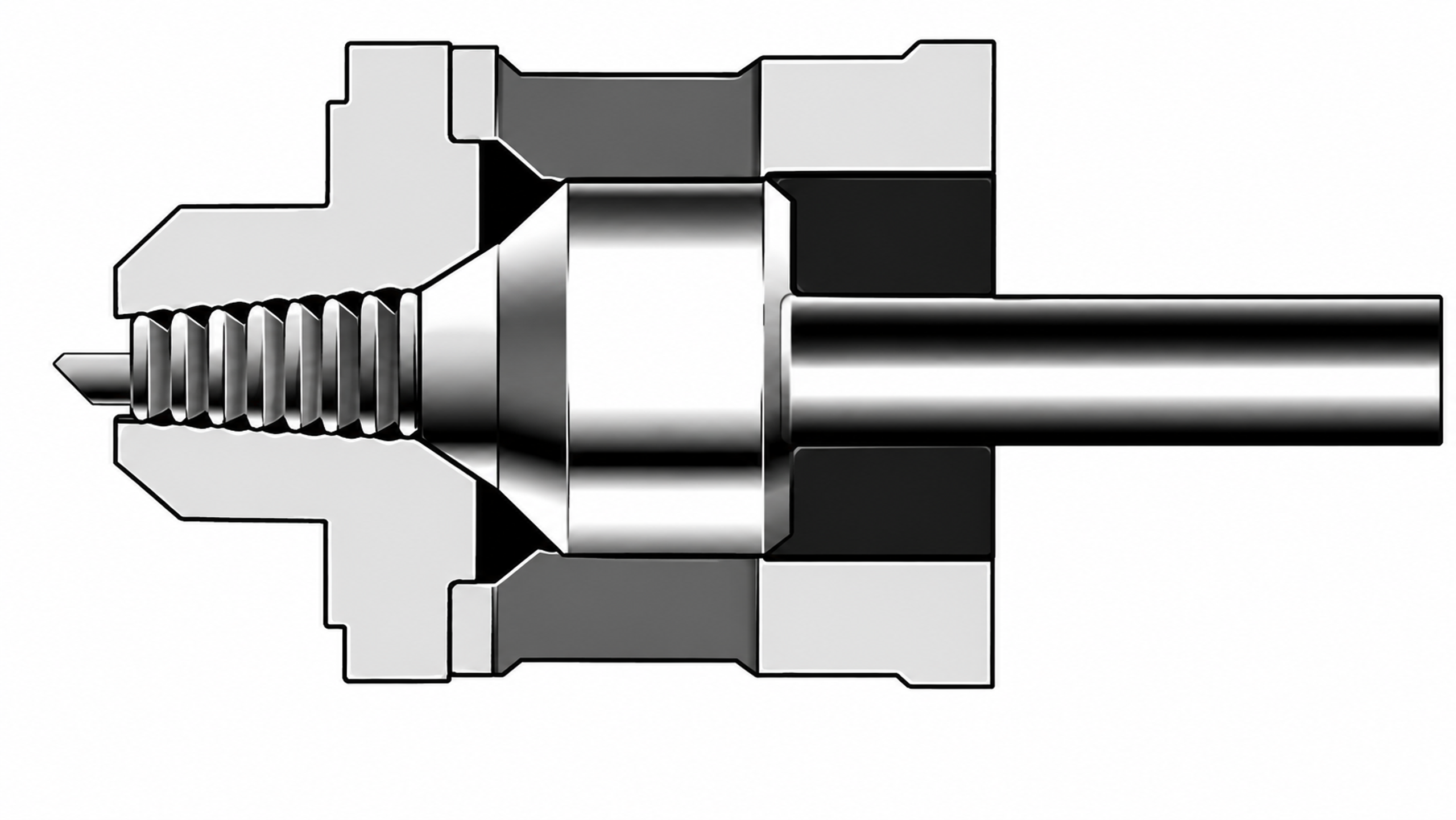
Figure 24. Cascade and labyrinth trim examples from Copes Vulcan and Valvitalia.
Copes Vulcan literature describes hot-water testing at very high differential pressure in which hardened Type 420 stainless-steel trim remained serviceable. The Valvitalia bulletin distinguishes cage-guided and top-guided cascade trims. Cage-guided construction is intended for larger ports and dirty or mildly abrasive service because its passages and plug-shearing action reduce the risk of clogging. Top-guided construction provides up to sixteen stages for small flow coefficients. [6, 7]
5.6 Axial Multistage Trims
In axial trims, flow proceeds along the valve axis through a sequence of notches, liners, or cages. When all stages throttle simultaneously, no stage becomes inactive at partial travel. This arrangement reduces the risk that inner stages become oversized while a final controlling edge carries most of the pressure drop. Axial staging also permits relatively large passages, strong plug guidance, and deliberate separation of the shutoff seat from the pressure-reducing elements. [3, 9, 10]
The LincolnLog design uses a sequence of three-dimensional, high-impedance pressure-reduction stages. The tortuous axial flow path distributes pressure loss and controls velocity through multiple active stages rather than concentrating the differential at a single restriction. [10]
Manufacturer literature describes LincolnLog configurations with as many as ten pressure-reduction stages for high-pressure liquid-letdown applications and pressure drops exceeding 8000 psi (approximately 550 bar). The design is intended for severe and remote services, including wellhead injection and offshore installations, where stage-by-stage pressure control is required. [10]
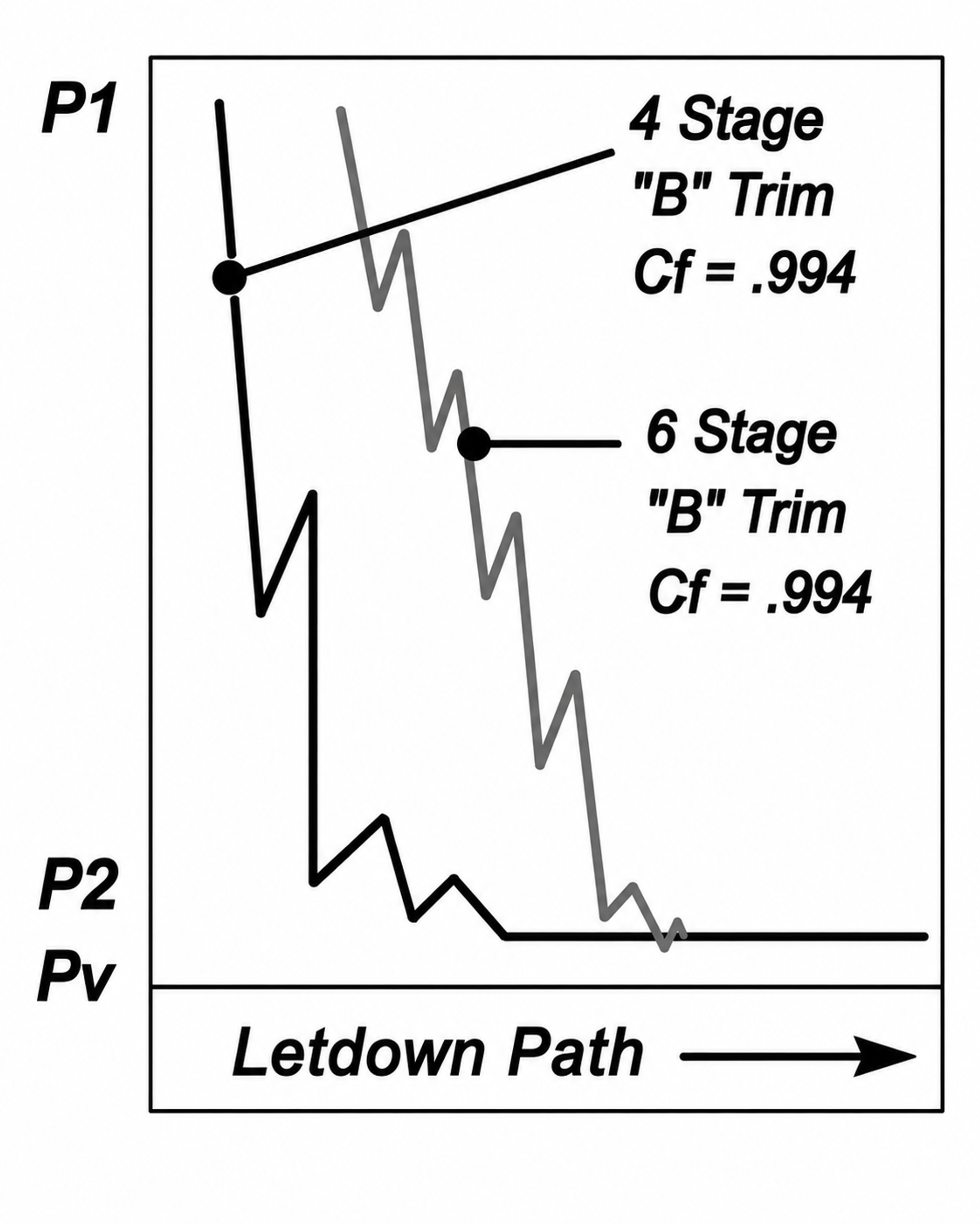
Figure 25. Multistage trim comparison for four- and six-stage configurations.
The axial arrangement throttles all stages concurrently throughout plug travel, limiting concentration of velocity and pressure drop at a single leading or controlling edge. The design objective is to reduce wear on the plug, cage, and seat by distributing the hydraulic load among the active stages. [10]
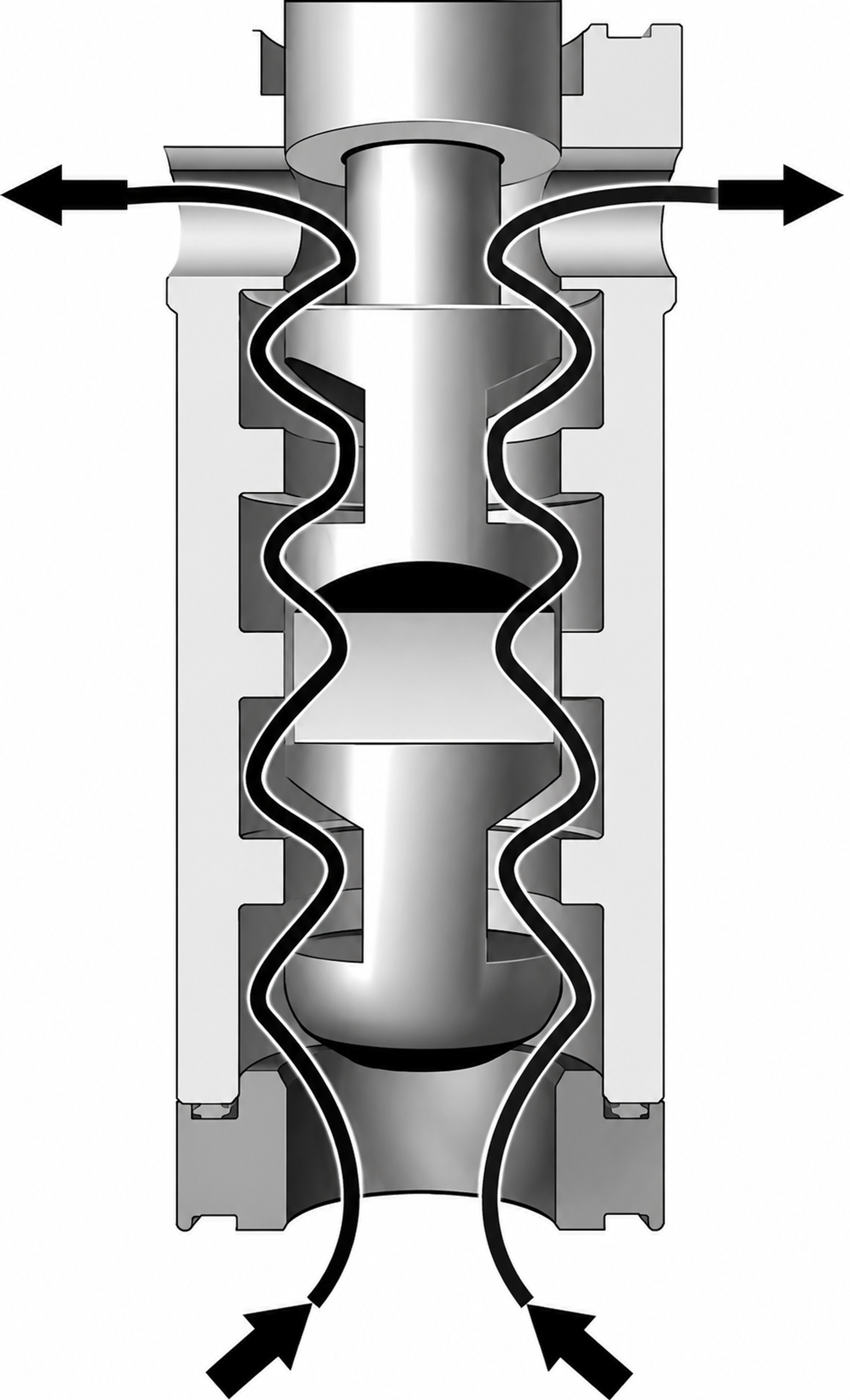
Figure 26. Axial-flow technology with three-dimensional multistage pressure reduction.
LincolnLog literature describes configurations with three to ten axial stages for high-pressure liquid letdown, with relatively large passages for debris tolerance and simultaneous stage activity throughout the stroke. The trim can be installed in globe or angle bodies and uses substantial plug guidance, hardened materials, and protected seats. [10]
5.7 Multistage Multipath Trims
Multipath trims divide total flow among numerous tortuous passages. The MIL Matrix concept combines axial or radial flow with a three-dimensional welded cage assembly and progressively expanding passages. Manufacturer literature describes very low pressure recovery, multiple pressure- and velocity-reduction stages, and designs with up to approximately fifty stages. The large number of small losses produces a gradual pressure decline rather than a few large pressure steps. [9]
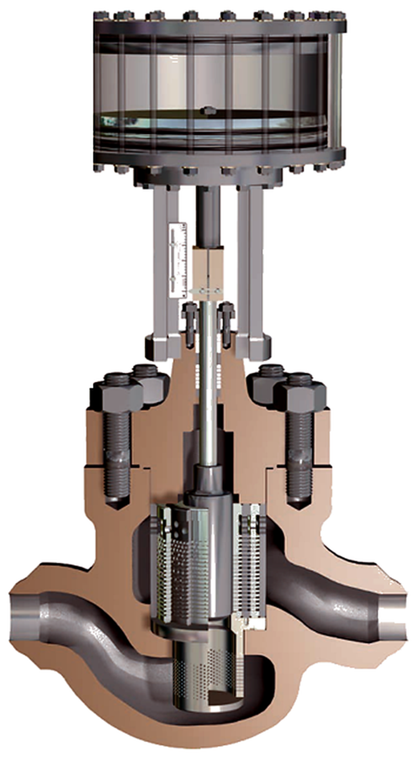
Figure 27. MIL Matrix multistage multipath control valve cutaway.
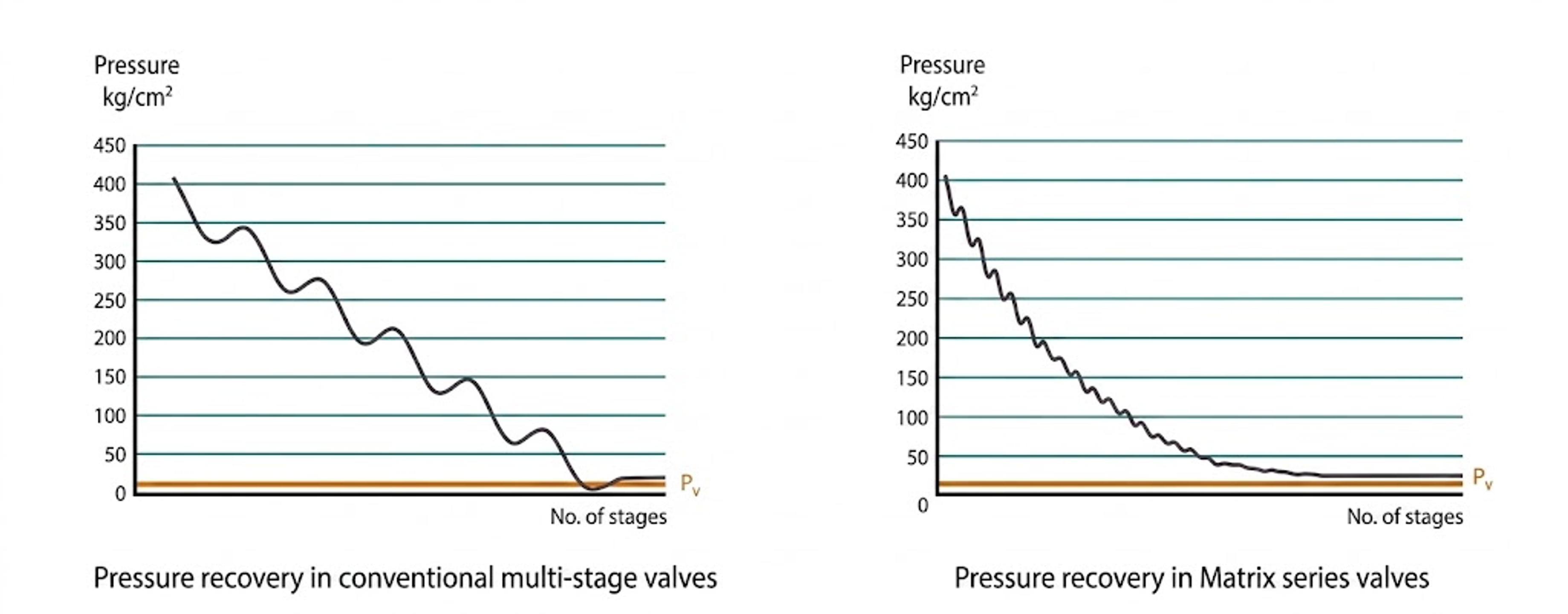
Figure 27. Comparison of conventional multistage pressure recovery with a progressively declining Matrix profile.
5.8 Dirty-Service Trims
Dirty-service design begins with the largest credible particle rather than the average solids concentration. The trim should provide a continuous passage larger than the design particle, minimize dead pockets, resist abrasive cutting, and protect the seat. Fisher Dirty Service Trim combines axial and radial flow paths, expanding flow area, a protected seat, and openings intended to pass relatively large particulate. Product literature states that a substantial portion of the total pressure drop is imposed before the final stage, reducing severity at the exit. [15]
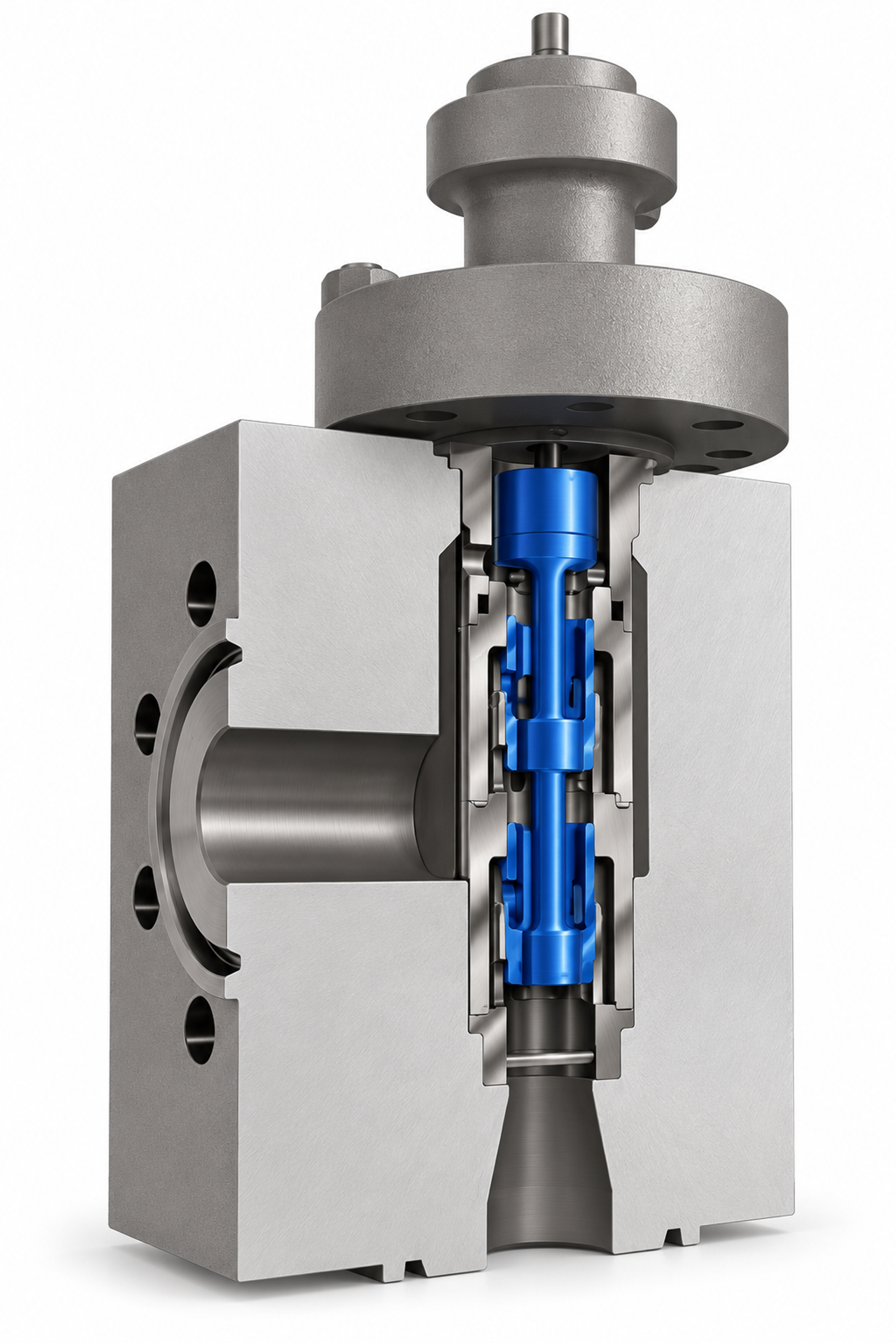
Figure 28. Fisher Dirty Service Trim for high-pressure-drop and particulate service.
Large-passage axial trims and cage-guided cascade trims provide alternative approaches for contaminated service. Fine ChannelStream, MicroCav, close-fitting perforated cages, and compact disk labyrinths are better suited to clean fluids unless adequate strainers and a defined cleanliness program are provided. [1, 2, 7, 10, 14, 15]
5.9 Rotary-Valve Cavitation Control
Rotary valves provide high capacity and compact construction, but conventional ball and butterfly valves can exhibit high pressure recovery and may cavitate at relatively modest pressure ratios. Cavitation control can be improved with characterized balls containing tortuous channels, downstream diffuser elements, or integral inserts containing repeated throats and expansion chambers. Rotary solutions are attractive when line-size capacity or solids tolerance is required, but trim effectiveness must be verified over the full range of rotation. [2, 15, 30]
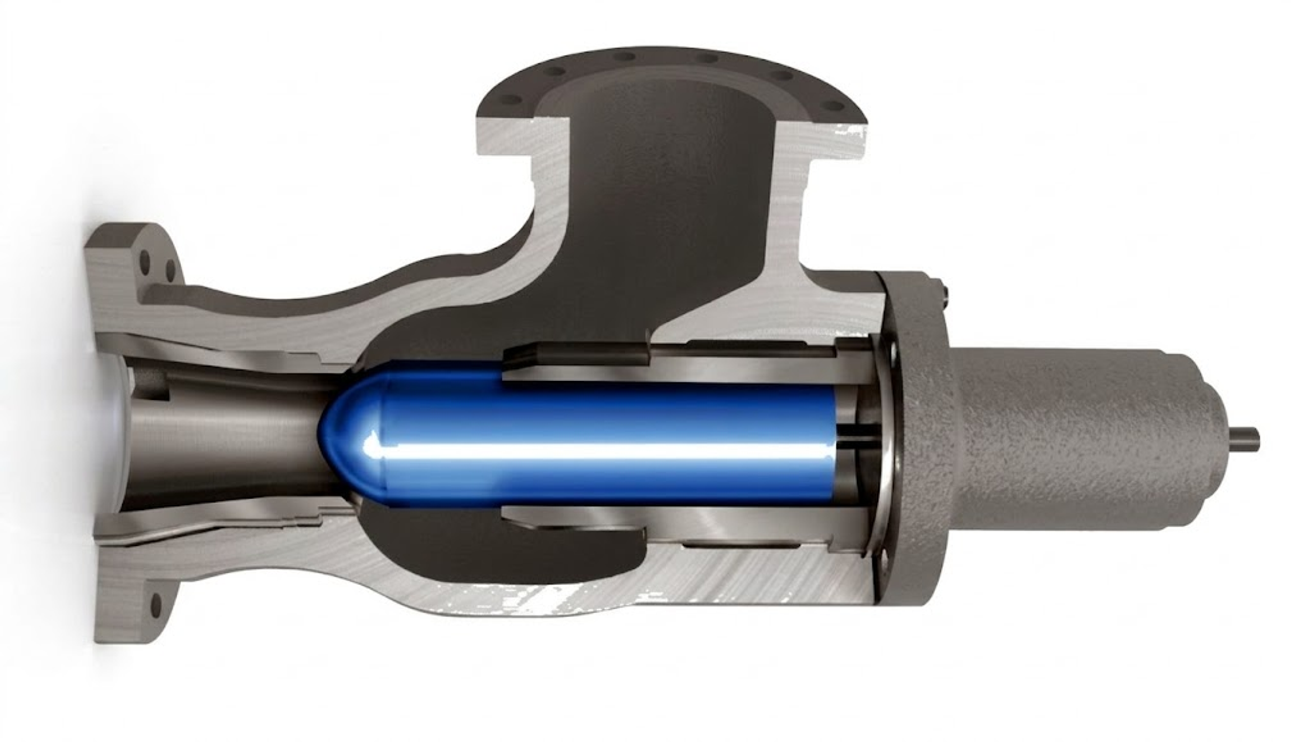
Figure 29. Fisher 461 sweep flow angle valve used for erosive and cavitating applications.
5.10 Fixed Energy Dissipators and Downstream Devices
A fixed multiorifice device can be effective when flow and pressure conditions remain relatively constant. Ross Model 890 uses an engineered multiorifice plate arrangement to dissipate hydraulic energy and limit large-scale eddies, while the Ross MOV uses two perforated plates whose relative alignment changes with travel. Fixed devices are mechanically simple and robust but cannot maintain an optimal pressure profile over a wide flow range. [4]
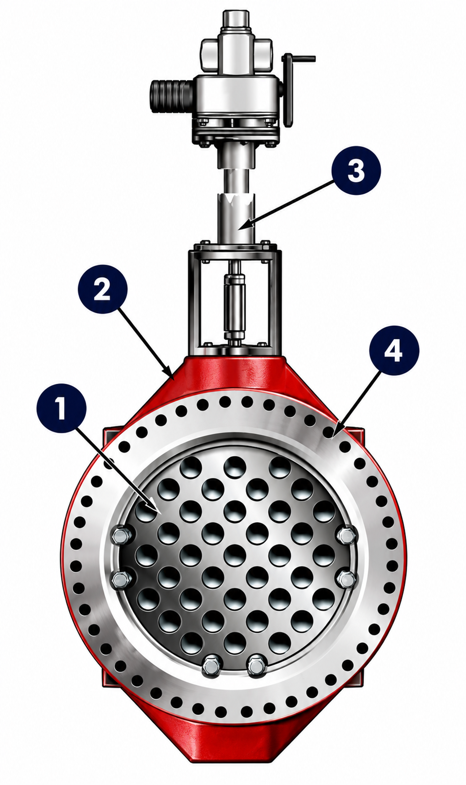
Figure 30. Ross Model MOV valve and numbered key features. 1 Two hardened stainless steel plates with custom designed orifices direct water to center of downstream pipe, safely dissipating energy. 2 Rugged construction throughout with heavy-duty shafts, bearing guides and seals. 3 Available automated or manual controls. 4 Narrow profile “space saving” design. Source: Ross Valve [4].
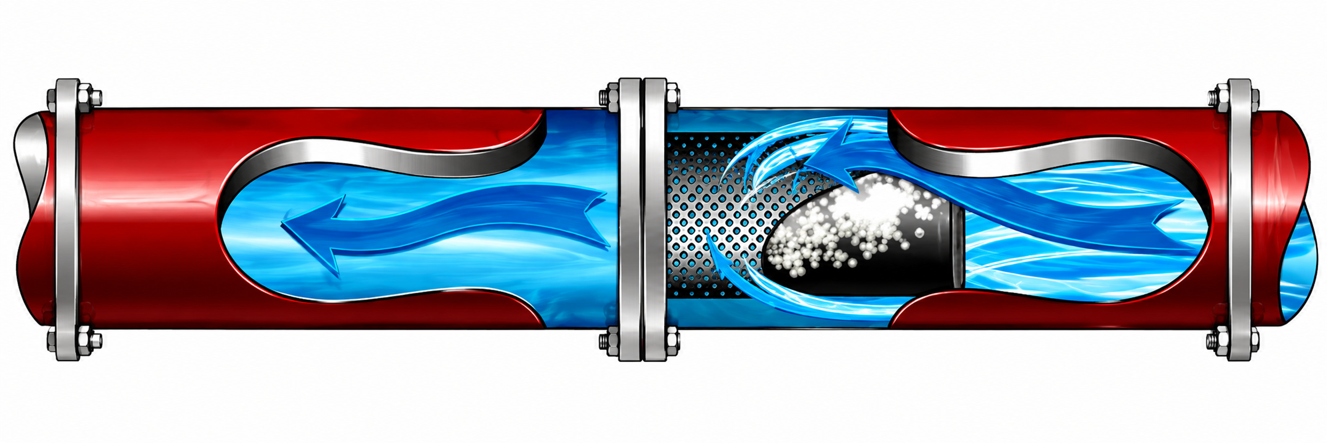
Figure 31. Ross Model 890 fixed energy dissipator flow.