
Technical publication
Back to publications
Reactors & equipment
Anti-Cavitation Control Valves
okozyuk.com
Published
Read complete publication for whole-document Find and printing. Browser Find and native printing on this reader include only loaded content.
Abstract
Cavitation in liquid control valves results from local pressure reduction below vapor pressure followed by vapor collapse during pressure recovery. The associated microjets, pressure waves, vibration, and unsteady hydraulic forces can cause trim erosion, pressure boundary damage, noise, loss of control authority, and reduced service life. This article presents a unified engineering treatment of cavitation physics, liquid valve sizing parameters, pressure recovery behavior, and anti-cavitation trim architecture. The discussion relates cavitation indices and liquid choking criteria to practical design strategies, including staged pressure reduction, opposed jet bubble isolation, stacked disk and concentric sleeve trims, axial multistage geometries, multipath trims, dirty service configurations, and fixed energy dissipators. Material selection, seat protection, outlet velocity, actuator stability, solids tolerance, and system layout are examined as coupled design variables. Application considerations are summarized for water distribution, power generation, oil and gas, petrochemical, and low flow injection services. A worked sizing example demonstrates preliminary severity assessment, choked flow capacity, stage count estimation, and hydraulic power dissipation. The article also reviews field diagnosis, maintenance, computational fluid dynamics, patent development, topology optimization, and additive manufacturing. Final valve selection should be based on the complete operating envelope and tested coefficients for the specific valve and trim geometry. Keywords: cavitation; control valves; anti-cavitation trim; pressure staging; liquid choking; valve sizing; severe service.
4. Hydraulic Design Principles for Anti-Cavitation Trims
4.1 Divide the Pressure Drop
The most direct way to prevent vapor formation is to divide the total pressure reduction into a sequence of smaller losses. If each stage has the same individual incipient coefficient and complete pressure recovery is assumed between idealized stages, the combined coefficient is
Solving for stage count gives
These equations provide a first estimate only. Real trims exhibit incomplete interstage pressure recovery, interacting jets, variable flow area, changes in fluid velocity, and stage coefficients that vary with travel. Detailed pressure-stage allocation therefore requires tested geometry or validated computational analysis. [3, 7, 9, 10, 17, 18]
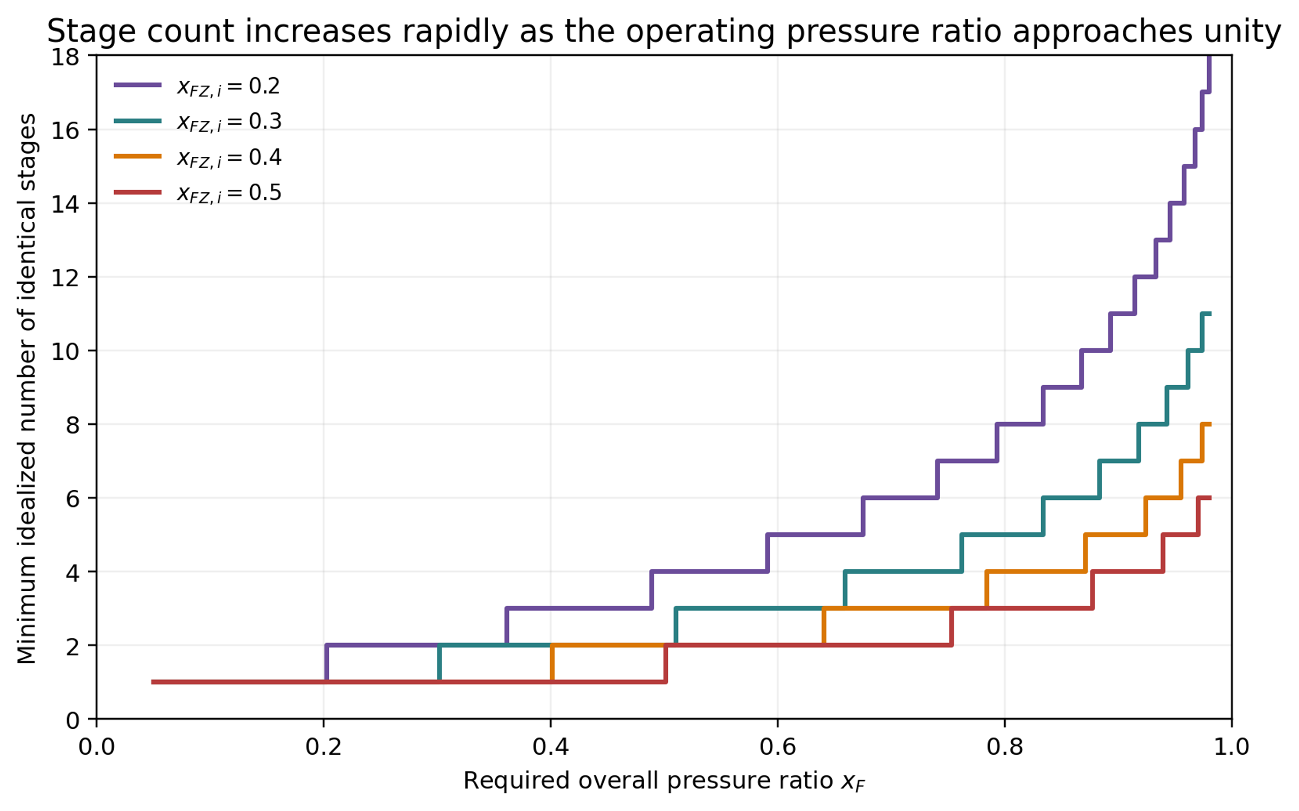
Figure 12. Idealized stage count as a function of operating pressure ratio and individual stage coefficient.
4.2 Allocate Stage Resistance to Control Velocity
Equal pressure drop per stage is not always optimal. In liquids, the pressure margin above vapor pressure decreases as static pressure falls. Later stages may therefore require smaller pressure drops, larger flow areas, or a different distribution of hydraulic resistance. Many severe-service trims use progressively expanding passages to prevent velocity from increasing downstream. Axial trims may use decreasing resistance from stage to stage, while disk stacks enlarge successive teeth or channels. [1, 2, 9, 10]
Equation (19) provides a convenient recurrence when each stage is defined by a pressure ratio relative to vapor pressure. The relationship also demonstrates the importance of absolute pressure: a pressure drop that is acceptable near the inlet can become cavitation-prone when imposed near the outlet. [3, 17, 18]
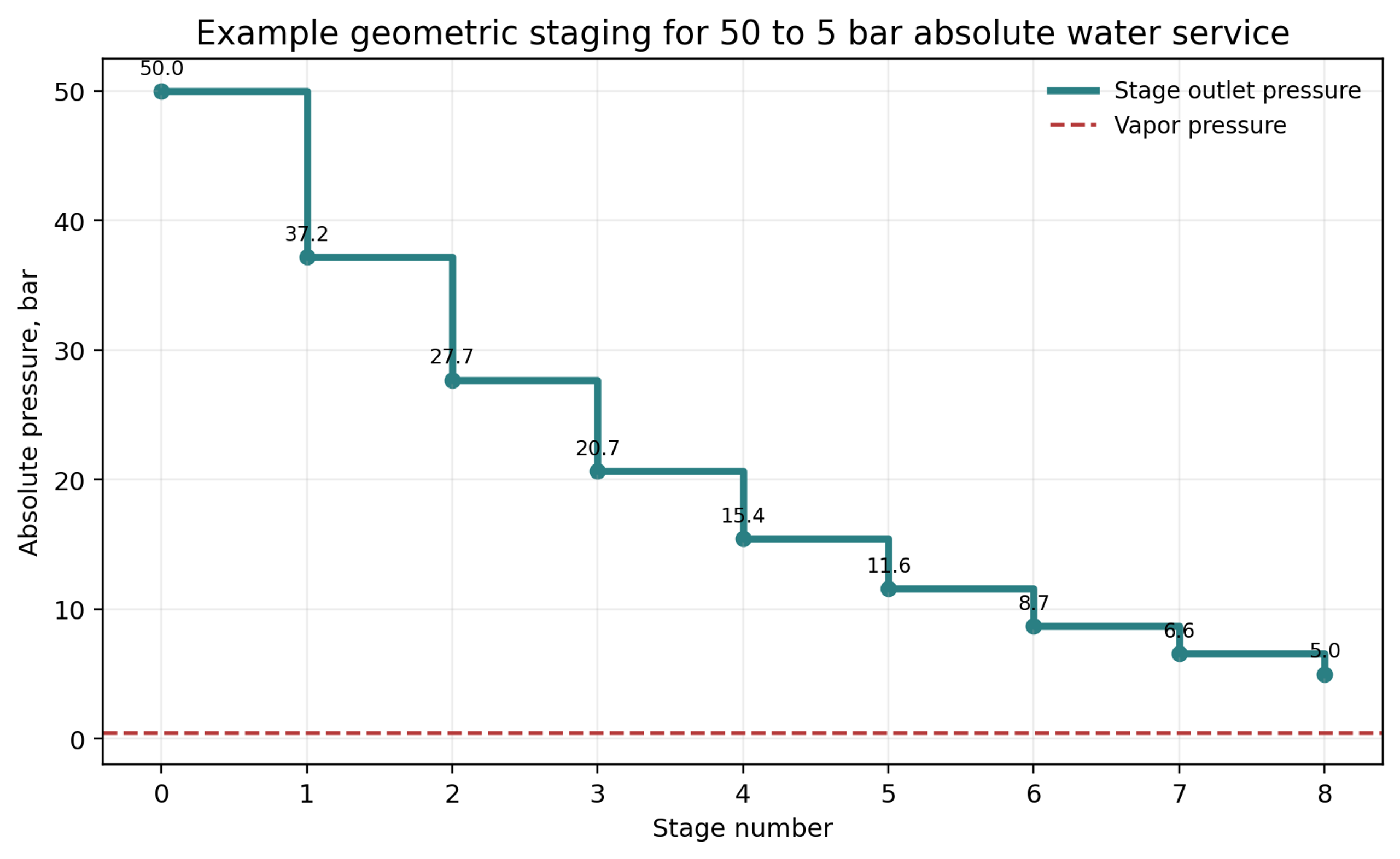
Figure 13. Geometric pressure staging for the worked example developed in Section 8.
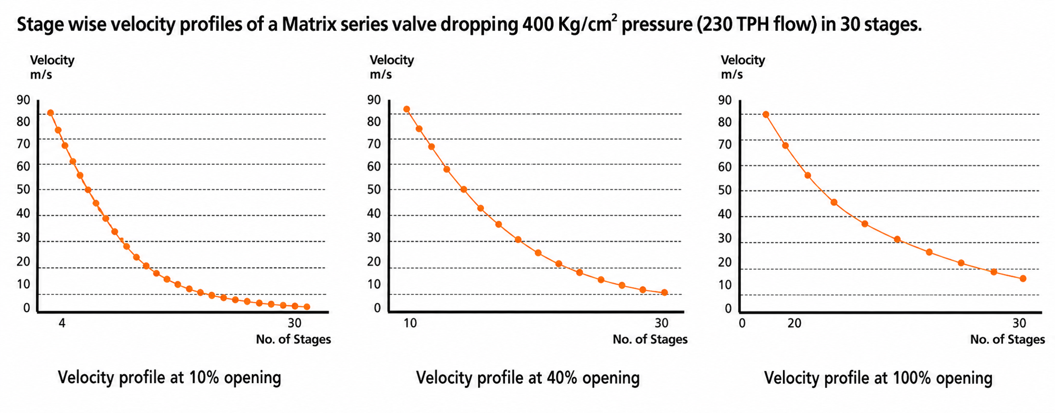
Figure 14. Stagewise velocity profiles for a thirty-stage Matrix valve at different openings.
4.3 Equivalent Capacity of Series Restrictions
For idealized incompressible restrictions in series, an equivalent coefficient can be estimated from
Increasing the number of stages reduces the capacity available from a trim of fixed nominal size. This tradeoff is fundamental. Greater cavitation resistance requires more wetted surface, longer passages, additional contractions, or greater flow subdivision, all of which consume pressure drop and trim volume. [3, 6-10, 13]
4.4 Mechanisms of Irreversible Energy Loss
Anti-cavitation trims combine sudden contraction and expansion, small-passage friction, mixing of converging streams, repeated changes in direction, surface impingement, mutual jet impingement, and controlled pressure recovery. These mechanisms convert organized kinetic energy into heat and small-scale turbulence while preventing a single dominant vena contracta from carrying the full pressure drop. [2, 14]
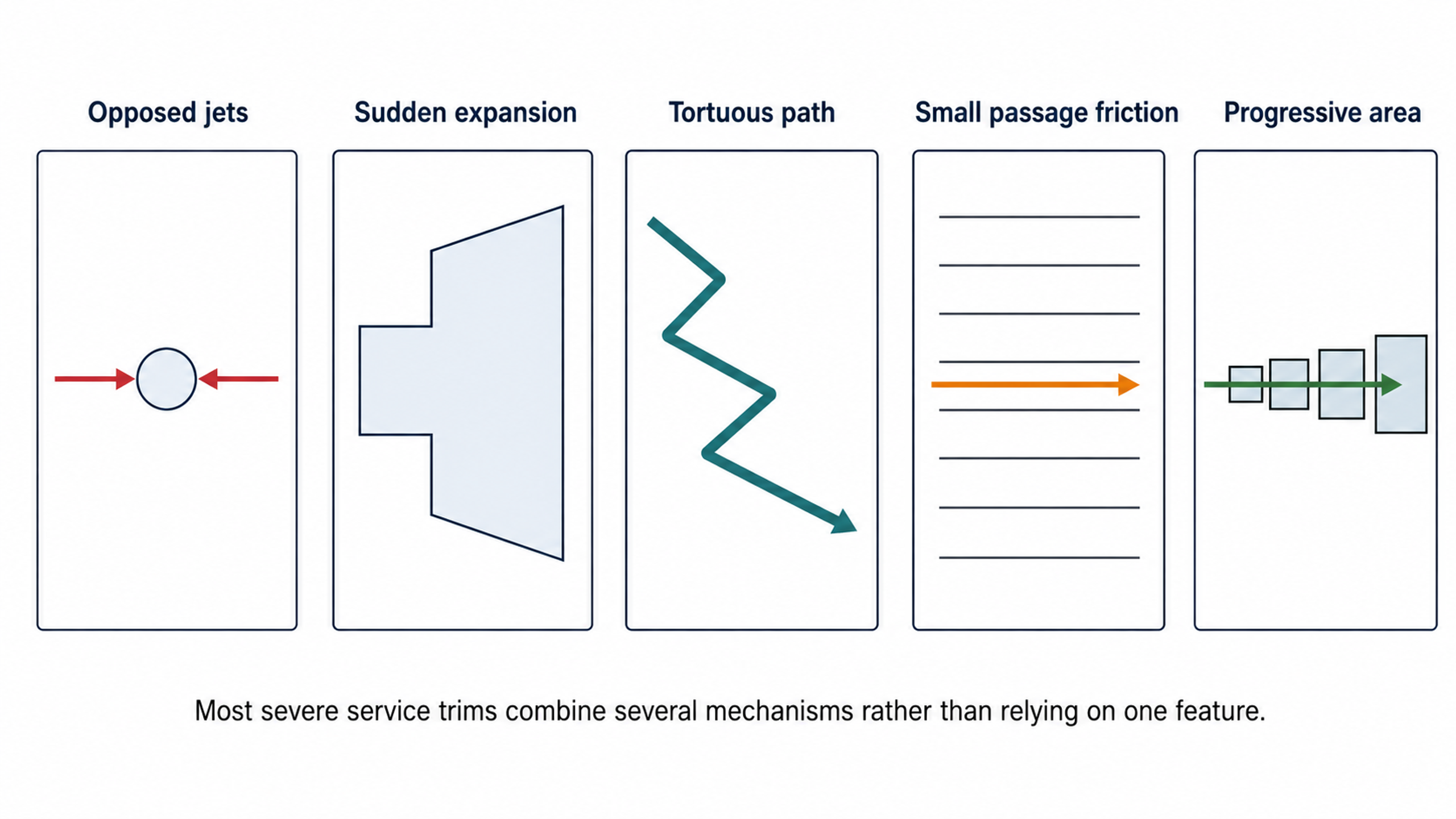
Figure 15. Principal energy dissipation mechanisms used in anti-cavitation trims.
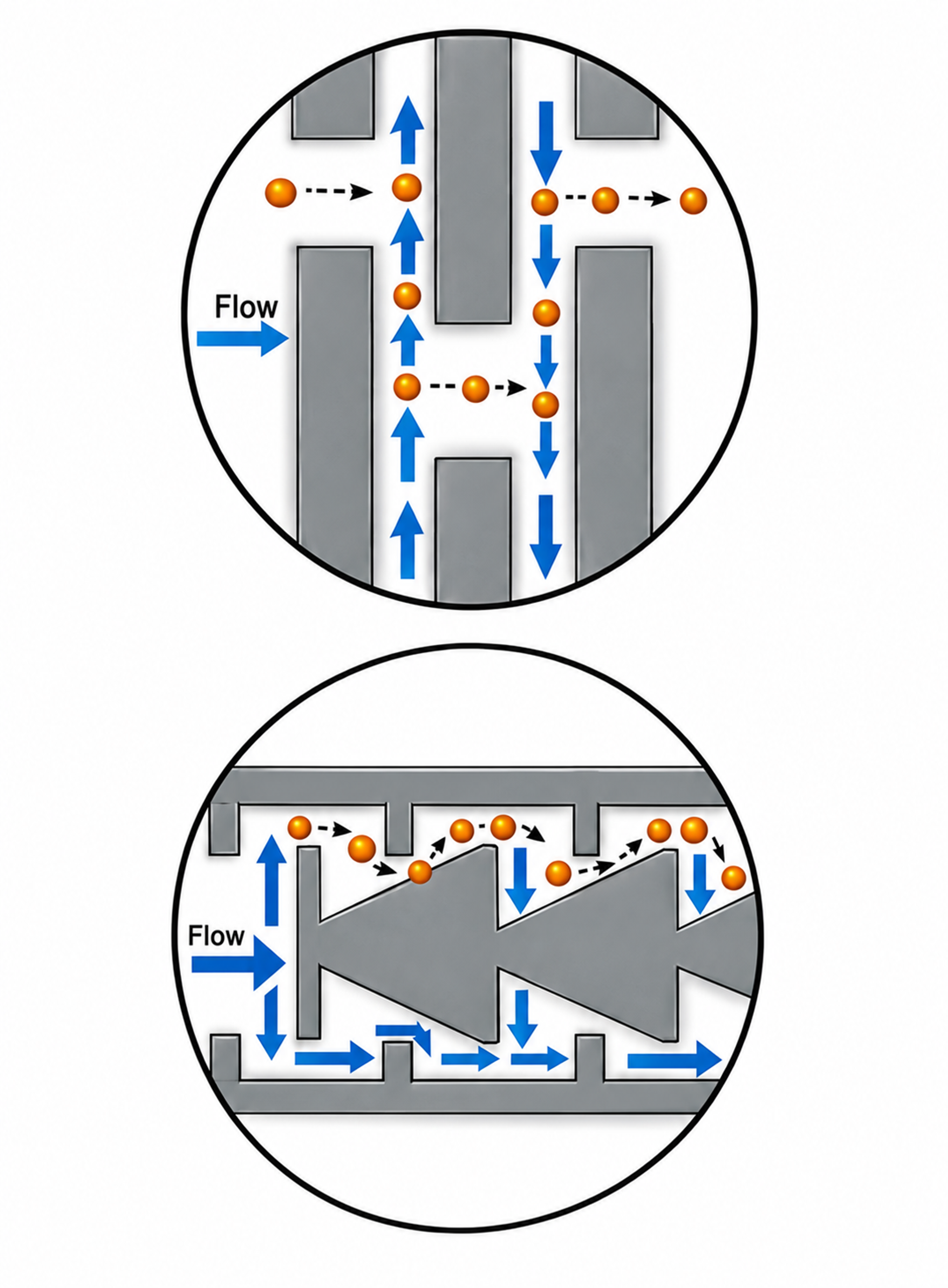
Figure 16. Examples of mechanism combinations for clean and dirty service.
4.5 Bubble Isolation by Opposed Jets
Under mild to moderate cavitation, diametrically opposed holes can direct cavitating jets toward the center of a cage. The opposing streams collide, surrounding the vapor field with liquid and promoting collapse away from the cage wall. Stepped holes are frequently used to create orifice-type behavior and move the vena contracta outside the metal passage. This mechanism is used in Flowserve CavControl, Singer dual-cage designs, Ross WaterTamer, Mascot CavFlo, and related waterworks valves. [1, 2, 4, 5, 11, 12]
Bubble isolation can control damage without eliminating vapor formation. Its capability becomes limited when the pressure drop is extremely severe, the collapse region extends beyond the protected core, or the flow field becomes asymmetric. Passage alignment, hole diameter, cage clearance, travel, and inlet distribution are therefore application-specific. [1, 2, 5, 11, 12]
4.6 Protect the Seat and Controlling Edge
Low-flow operation is often a severe condition because nearly the full pressure drop is concentrated near the seat while the opening is small. Robust designs separate shutoff from throttling. Applicable strategies include trim overlap, a sacrificial upstream seal, a plug chamber that fills before the principal stages open, tandem seats, and placement of the controlling edge downstream from the shutoff surface. [2, 6-10, 15]
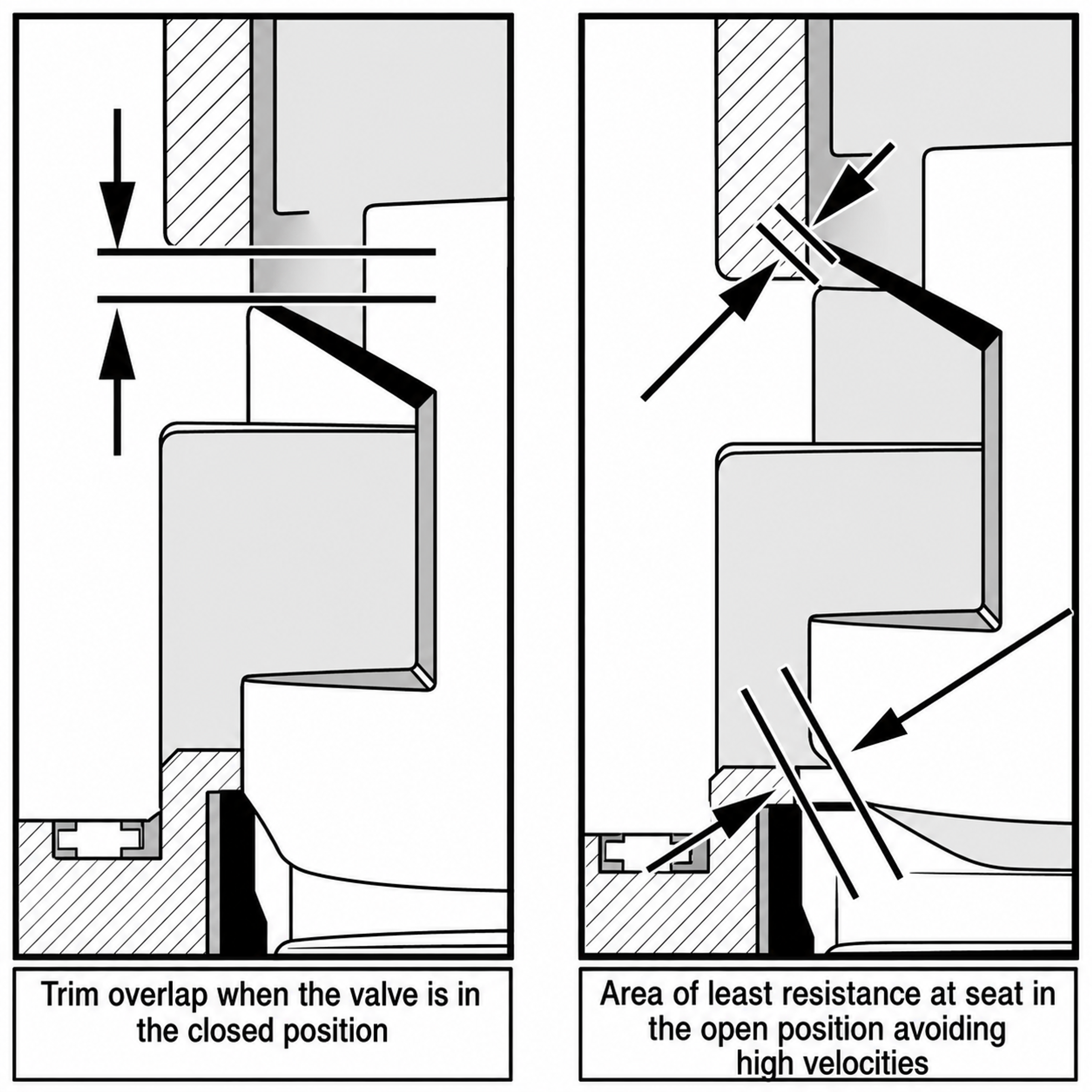
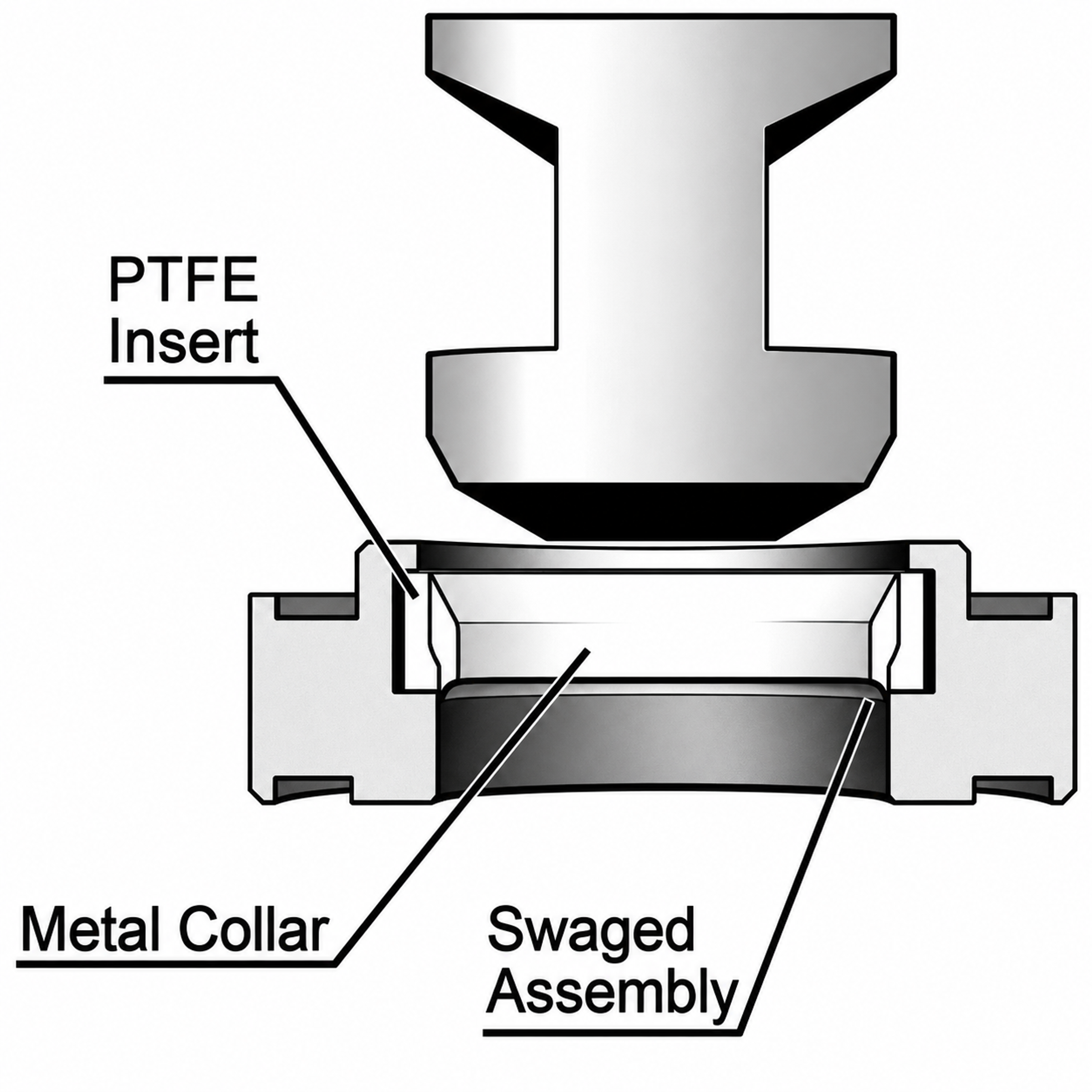
Figure 17. Separation of shutoff and throttling functions in an axial multistage trim.
4.7 Manage Outlet Velocity and Gallery Flow
A large valve body is not inherently excessive. The body gallery must maintain adequate separation between the cavity field and the pressure boundary while distributing flow uniformly around the trim. A preliminary outlet velocity is
The Valtek sizing guide recommends approximately 9.1 meters per second as a practical limit for cavitating or near-saturation liquid service, whereas SAMSON guidance for cavitating operation uses a more conservative outlet velocity near 4 meters per second for its erosion limits. These values are design guides rather than universal limits. The appropriate criterion depends on valve geometry, pressure, fluid properties, piping, and manufacturer experience. [3, 13]
4.8 Consider the Process Loop Before Adding Trim
Cavitation can sometimes be reduced by relocating the valve so that a larger fraction of system resistance remains downstream, thereby increasing valve outlet pressure. Discharge into a vessel, use of a downstream diffuser, or redistribution of pressure drop among several devices can also be effective. A downstream orifice plate can reduce the pressure drop across the valve, but it may transfer cavitation to the plate and is effective only over a limited flow range. [4, 5, 11, 15]
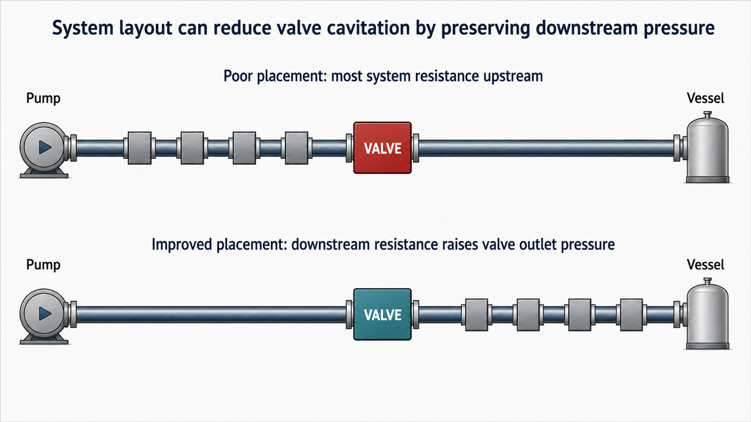
Figure 18. Effect of valve location on available downstream pressure.