
Technical publication
Back to publications
Reactors & equipment
Anti-Cavitation Control Valves
okozyuk.com
Published
Read complete publication for whole-document Find and printing. Browser Find and native printing on this reader include only loaded content.
Abstract
Cavitation in liquid control valves results from local pressure reduction below vapor pressure followed by vapor collapse during pressure recovery. The associated microjets, pressure waves, vibration, and unsteady hydraulic forces can cause trim erosion, pressure boundary damage, noise, loss of control authority, and reduced service life. This article presents a unified engineering treatment of cavitation physics, liquid valve sizing parameters, pressure recovery behavior, and anti-cavitation trim architecture. The discussion relates cavitation indices and liquid choking criteria to practical design strategies, including staged pressure reduction, opposed jet bubble isolation, stacked disk and concentric sleeve trims, axial multistage geometries, multipath trims, dirty service configurations, and fixed energy dissipators. Material selection, seat protection, outlet velocity, actuator stability, solids tolerance, and system layout are examined as coupled design variables. Application considerations are summarized for water distribution, power generation, oil and gas, petrochemical, and low flow injection services. A worked sizing example demonstrates preliminary severity assessment, choked flow capacity, stage count estimation, and hydraulic power dissipation. The article also reviews field diagnosis, maintenance, computational fluid dynamics, patent development, topology optimization, and additive manufacturing. Final valve selection should be based on the complete operating envelope and tested coefficients for the specific valve and trim geometry. Keywords: cavitation; control valves; anti-cavitation trim; pressure staging; liquid choking; valve sizing; severe service.
3. Cavitation Indices and Valve Sizing
3.1 Pressure Definitions
| Symbol | Definition | Engineering note |
|---|---|---|
| p₁ | Upstream absolute pressure | Use a representative location with a developed inlet profile. |
| p₂ | Downstream absolute pressure | Avoid substituting gauge pressure in vapor pressure relations. |
| Vapor pressure at flowing temperature | For mixtures, use a justified effective vapor pressure or vendor method. | |
| or | Minimum local pressure | Usually inferred from test coefficients rather than measured directly. |
| Δp | p₁ − p₂ | Actual valve pressure drop. |
| Thermodynamic critical pressure | Used in the liquid critical pressure ratio factor. |
Table 1. Pressure quantities used in liquid valve sizing.
3.2 Sigma Cavitation Index
A commonly used cavitation index expresses the available pressure margin above vapor pressure relative to the imposed pressure drop across the valve.
High means a relatively large pressure margin and low cavitation severity. Low means a severe pressure reduction. A value at or below unity indicates that the downstream pressure is at or below vapor pressure and flashing is expected. Manufacturer limits are developed by test for specific valve styles. They are not universal material constants and must be corrected where size and pressure scale effects are significant. [1, 2, 14, 16]
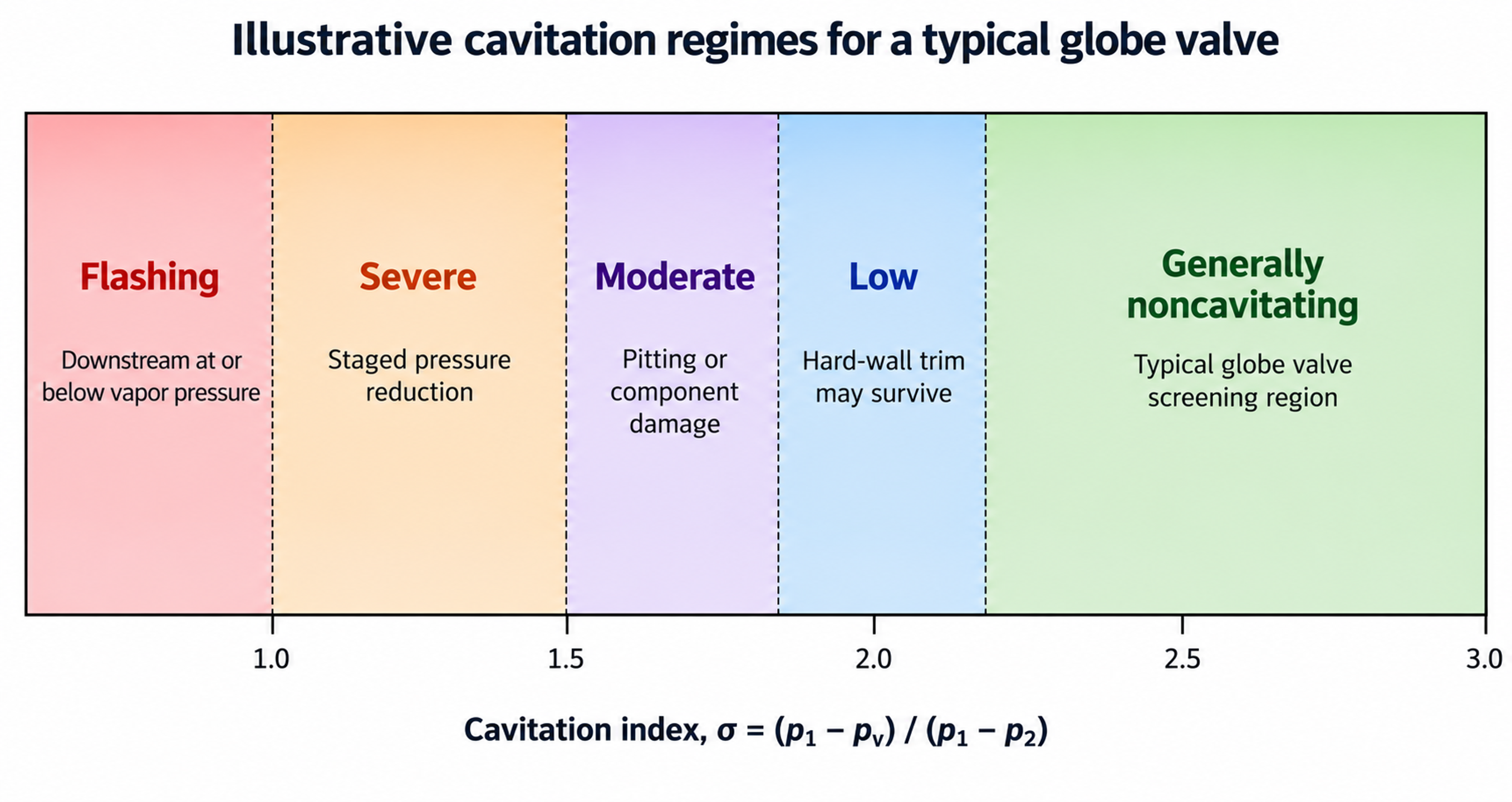
Figure 9. Illustrative regimes for a typical globe valve.
The supplied Flowserve data illustrate how a conventional globe valve can reach choked cavitation at a lower Sigma than the Sigma associated with the beginning of damage. Their example gives approximately and for a particular test valve. The same bulletin classifies staged trims such as Tiger Tooth and ChannelStream for Sigma values approaching 1.002, while opposed jet trim is intended for less severe conditions. These figures are useful for understanding relative severity but are not transferable without the manufacturer scaling procedure. [1, 2]
3.3 Operating Pressure Ratio and Incipient Cavitation Coefficient
IEC-style liquid sizing commonly uses the operating pressure ratio
which is the inverse of Sigma when the same pressure locations and absolute units are used. A valve specific incipient cavitation coefficient can be represented as
At the measured onset of cavitation, is commonly related to vapor pressure through the test method. Cavitation free operation requires the operating to remain below the applicable with an engineering margin. Because changes with travel and trim geometry, full stroke data are required for modulating service. [3, 17, 18]
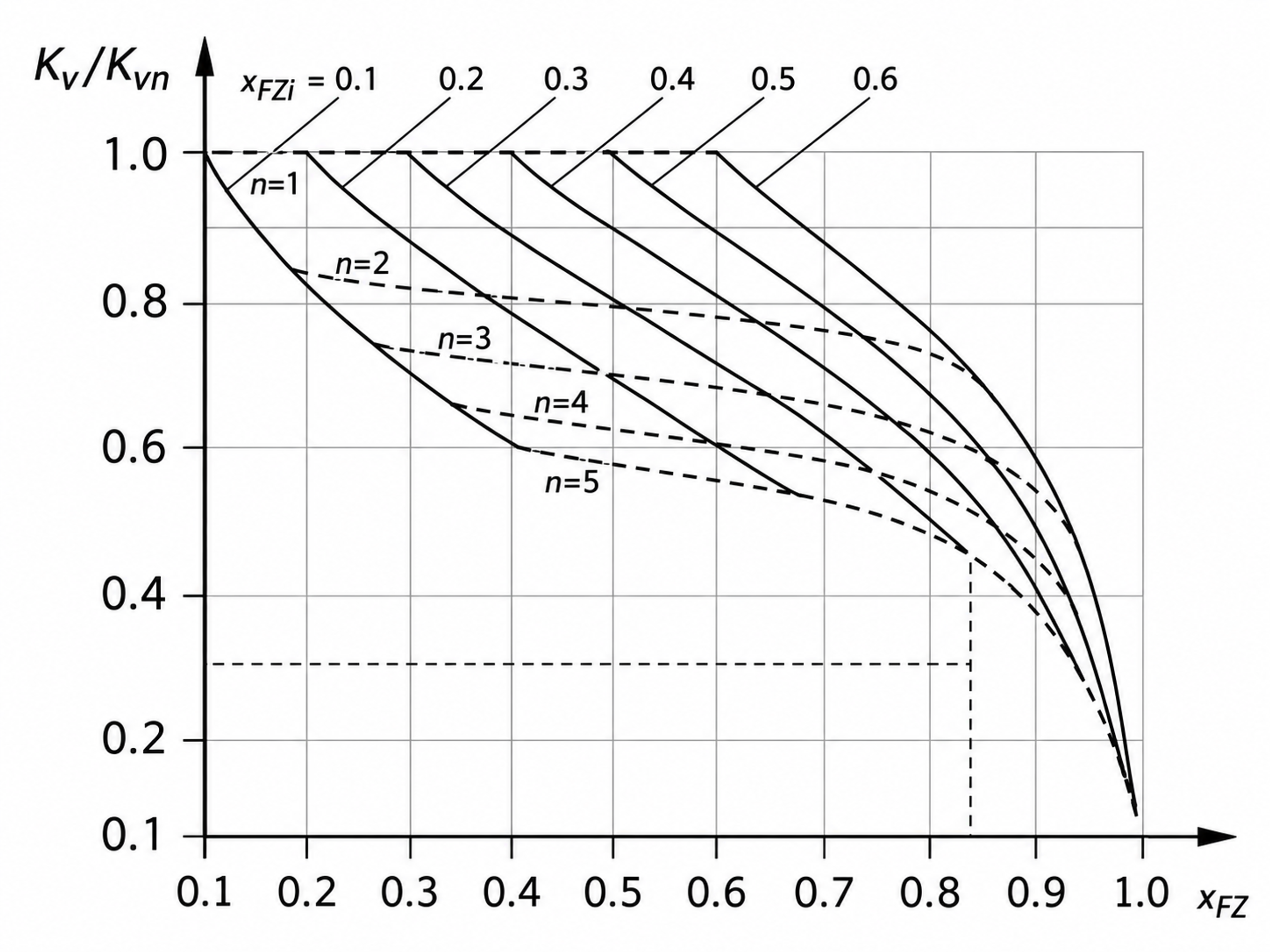
Figure 10. Relationship among multistage valve coefficient, capacity ratio, and the number of stages.
3.4 Liquid Critical Pressure Ratio Factor and Choked Pressure Drop
For preliminary liquid sizing, the liquid critical pressure ratio factor can be estimated from the vapor pressure and thermodynamic critical pressure.
For a valve without attached fittings, a commonly used choked-pressure-drop relation is
For capacity calculations, the allowable pressure drop is the smaller of the actual pressure drop and the choked pressure drop.
The liquid pressure recovery factor is determined by test and reflects valve geometry. High recovery rotary valves generally have lower and are more susceptible to cavitation at a given overall pressure drop than low recovery globe or multistage valves. Attached reducers and expanders require the combined coefficient and piping geometry factor . [13, 17, 18]
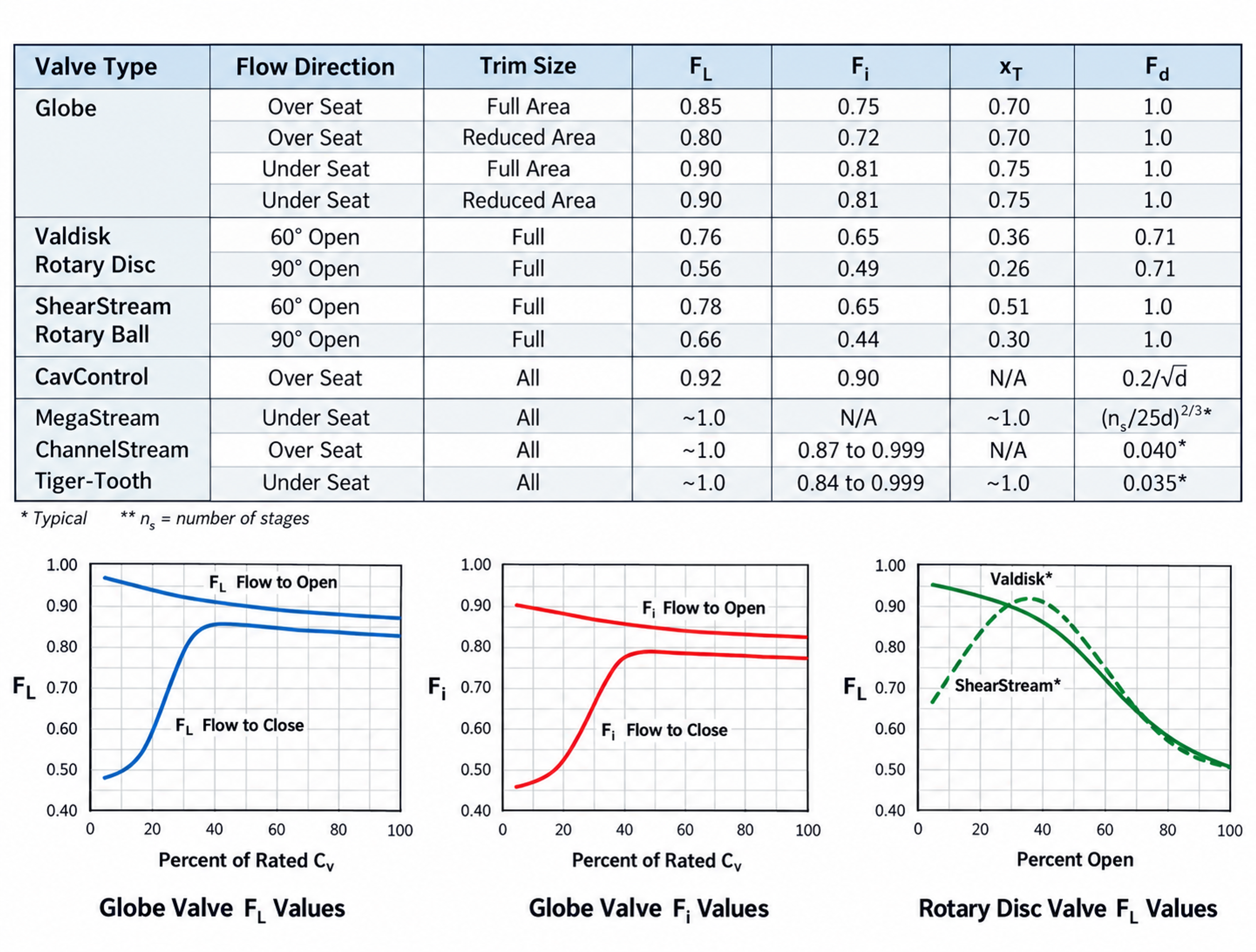
Figure 11. Typical valve pressure recovery coefficients and part travel trends, with liquid sizing relations.
3.5 Flow Coefficient
For turbulent incompressible flow in SI units, a convenient preliminary relationship is
where is in cubic meters per hour and pressure is in bar. The corresponding customary coefficient is approximately
Viscous, low-Reynolds-number, non-Newtonian, multiphase, and slurry services require additional corrections or a different flow model. A valid anti-cavitation selection must also satisfy minimum controllable flow, maximum flow, normal operating travel, rangeability, shutoff, and actuator-force requirements. [13, 17, 18]
3.6 Substantial Cavitation and Manufacturer Criteria
Some sizing systems use a liquid cavitation factor to estimate the pressure drop at which substantial cavitation begins.
The factor is specific to valve style, flow direction, and travel. It is useful for screening, but severe high-pressure service requires manufacturer assessment of absolute pressure, pressure and size scaling, material, residence time, trim-passage geometry, and the location of pressure recovery. [1, 13, 14]
3.7 Scale Effects
Laboratory cavitation data are commonly obtained with water over limited pressure and size ranges. Collapse intensity, cavity length, active-nuclei population, and exposed area can vary with valve size and absolute pressure. ISA practice and manufacturer methods therefore apply size and pressure scale corrections to a reference Sigma. A general representation is
where and are manufacturer determined scale effects. The relation is not a substitute for vendor data. It emphasizes that a favorable small-scale test coefficient cannot be applied directly to a large high pressure valve. [14, 16, 32]