
Technical publication
Back to publications
Reactors & equipment
Anti-Cavitation Control Valves
okozyuk.com
Published
Read complete publication for whole-document Find and printing. Browser Find and native printing on this reader include only loaded content.
Abstract
Cavitation in liquid control valves results from local pressure reduction below vapor pressure followed by vapor collapse during pressure recovery. The associated microjets, pressure waves, vibration, and unsteady hydraulic forces can cause trim erosion, pressure boundary damage, noise, loss of control authority, and reduced service life. This article presents a unified engineering treatment of cavitation physics, liquid valve sizing parameters, pressure recovery behavior, and anti-cavitation trim architecture. The discussion relates cavitation indices and liquid choking criteria to practical design strategies, including staged pressure reduction, opposed jet bubble isolation, stacked disk and concentric sleeve trims, axial multistage geometries, multipath trims, dirty service configurations, and fixed energy dissipators. Material selection, seat protection, outlet velocity, actuator stability, solids tolerance, and system layout are examined as coupled design variables. Application considerations are summarized for water distribution, power generation, oil and gas, petrochemical, and low flow injection services. A worked sizing example demonstrates preliminary severity assessment, choked flow capacity, stage count estimation, and hydraulic power dissipation. The article also reviews field diagnosis, maintenance, computational fluid dynamics, patent development, topology optimization, and additive manufacturing. Final valve selection should be based on the complete operating envelope and tested coefficients for the specific valve and trim geometry. Keywords: cavitation; control valves; anti-cavitation trim; pressure staging; liquid choking; valve sizing; severe service.
7. Application Engineering and Selection
7.1 Required Process Data
A complete valve data sheet should include every relevant operating case, not only the design maximum. Minimum flow and startup can produce the highest pressure ratio, whereas maximum flow often governs body and passage velocity. The following information is required for a defensible selection.
| Category | Required data | Why it matters |
|---|---|---|
| Pressure | Minimum, normal, and maximum p₁ and p₂, all as absolute values | Establishes pressure ratio, choking, flashing, and actuator load. |
| Flow | Minimum controllable, normal, maximum, startup, shutdown, bypass, and relief flow | Determines rangeability, stage activation, and velocity. |
| Fluid | Composition, density, viscosity, vapor pressure, critical pressure, gas content | Controls capacity, nucleation, and collapse intensity. |
| Temperature | Normal and transient range | Changes vapor pressure, density, viscosity, materials, and seals. |
| Solids | Concentration, hardness, shape, maximum particle, expected debris | Determines minimum passage and erosion resistant material. |
| Piping | Line size, reducers, expanders, elevations, downstream resistance, vessel connection | Changes installed coefficients, outlet velocity, and recovery. |
| Control | Characteristic, fail action, stroke speed, shutoff class, actuator supply | Determines controllability and mechanical design. |
| Reliability | Required life, inspection interval, spare trim philosophy, acceptable noise and vibration | Sets margin, material, and maintainability. |
Table 2. Minimum information for anti-cavitation valve selection.
7.2 Severity and Fluid-Cleanliness Map
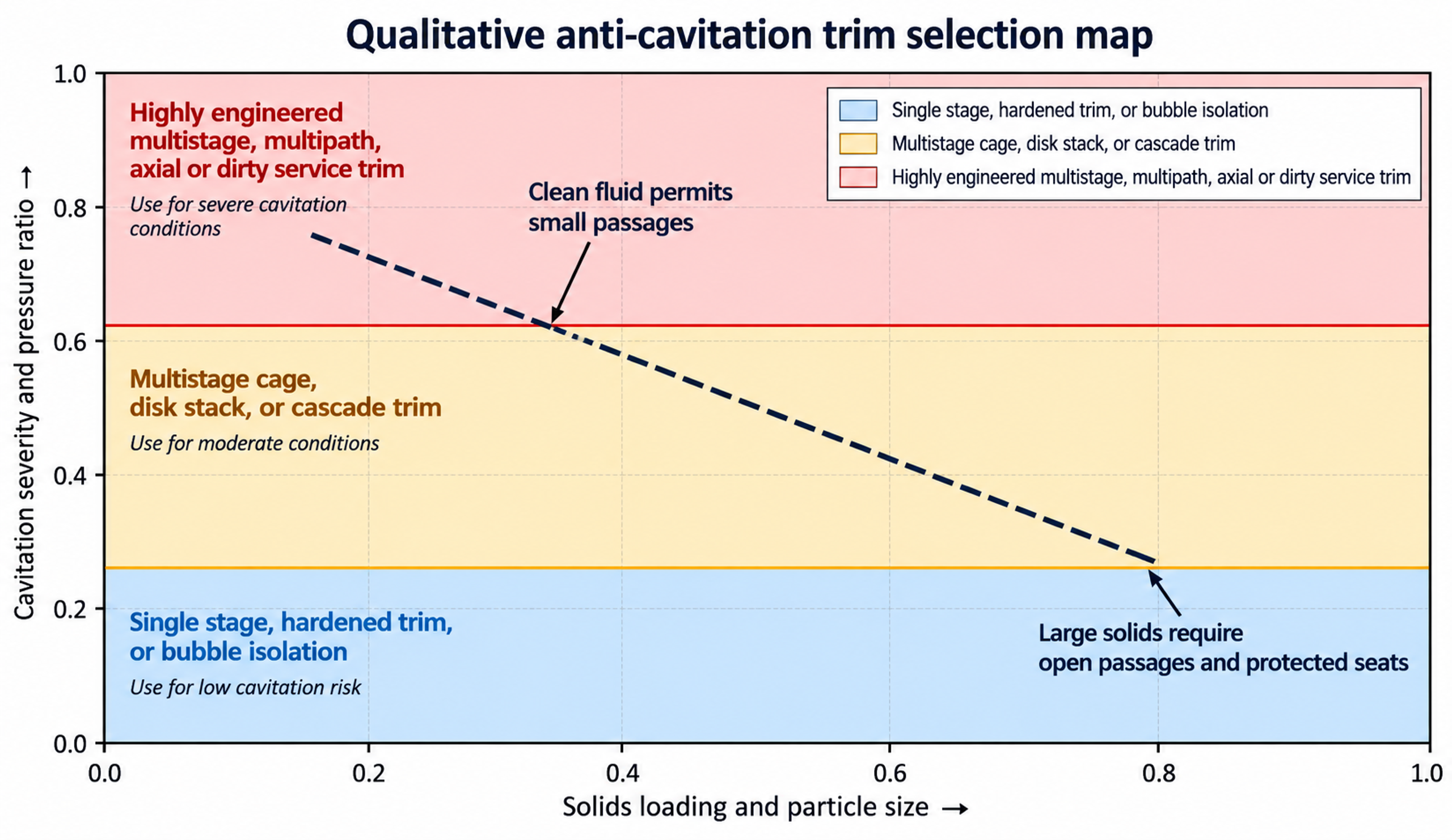
Figure 33. Qualitative selection map based on cavitation severity and solids loading.
The map is intentionally qualitative; vendor-tested coefficients define the actual application boundary. It illustrates a practical tradeoff: increasing cavitation resistance through smaller and more numerous passages generally increases sensitivity to solids. Dirty-service capability therefore tends to require greater trim volume, lower capacity for a given body size, or less compact flow geometry. [7, 9, 10, 14, 15]
7.3 Water Distribution, High-Rise, and Reservoir Service
Large automatic valves in water systems may reduce transmission pressure to a distribution zone, accommodate major elevation changes, fill elevated reservoirs, discharge to atmosphere, or provide continuous pressure relief. Singer literature uses an outlet pressure near or below approximately 30% of inlet pressure as a screening condition for anti-cavitation trim and illustrates a practical 3:1 pressure-ratio rule. This criterion is a screening aid and does not replace detailed calculation. [5, 11]
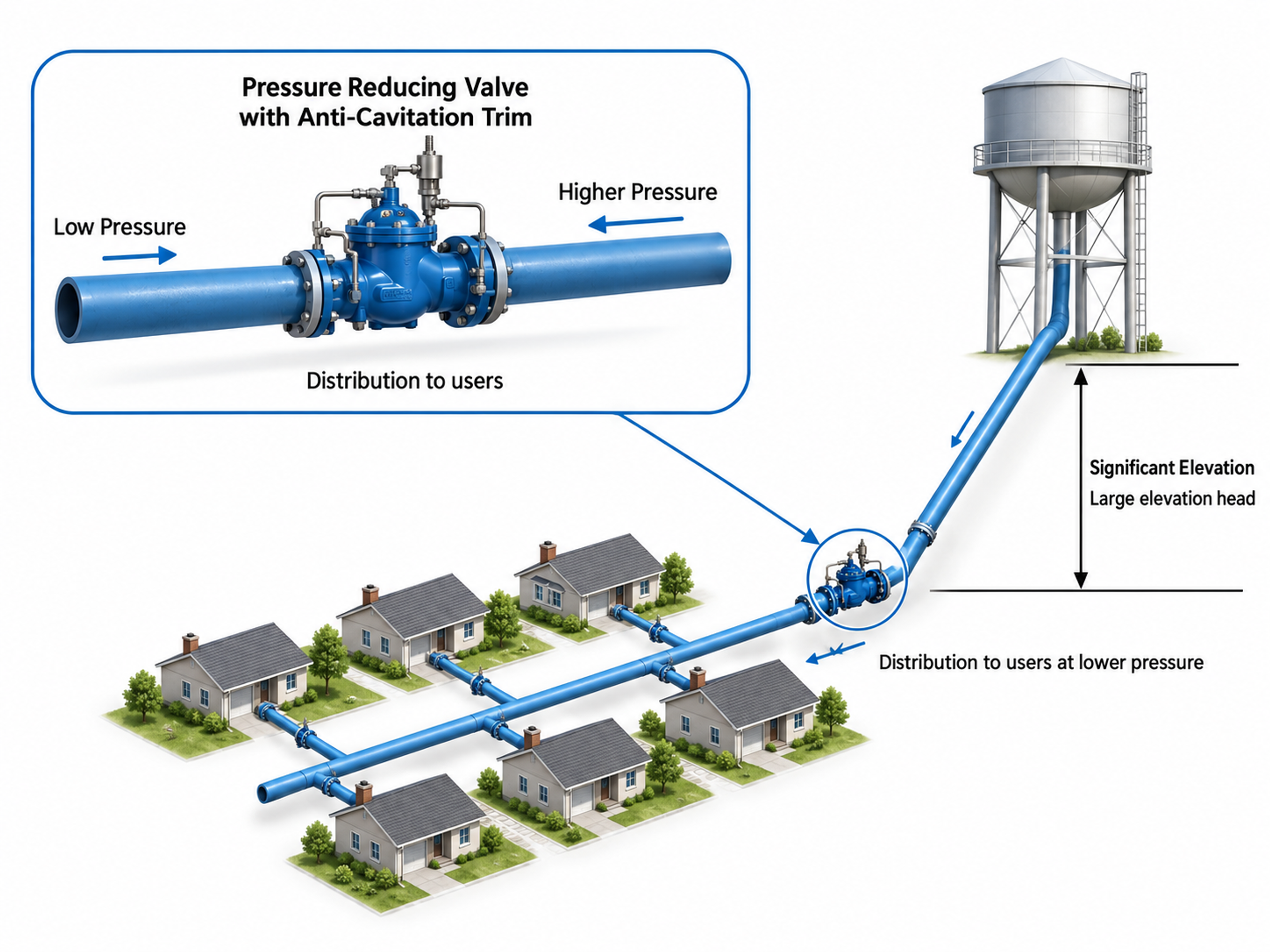
Figure 34. Water distribution pressure reduction application.
Reservoir filling to atmosphere and submerged discharge require particular attention because downstream static head, siphoning, and air entrainment can alter the actual outlet pressure. A discharge line that becomes submerged may develop a pressure profile different from the nominal atmospheric case. The complete line elevation and operating sequence should therefore be included in the hydraulic model. [4, 5, 11]
7.4 Power-Plant Service
Power plants contain several demanding liquid-valve applications, including boiler-feed-pump minimum recirculation, startup feed control, desuperheater and attemperator spray water, blowdown, drain, warmup, and injection service. A single valve may experience high inlet pressure, low outlet pressure, rapid transients, magnetite or weld debris, tight-shutoff requirements, and long closed periods. [2, 6-10, 15]
When boiler-feed demand falls below the pump minimum-flow requirement, the recirculation system returns part of the high-pressure flow through a minimum-recirculation control valve. The valve is typically open during pump startup and closes as system flow increases. This service is severe because the valve may be required to sustain a large pressure drop and intense cavitation while maintaining acceptable erosion, vibration, and noise. The valve may be configured for on/off or modulating duty according to plant design. [9]
Design considerations
-
Capability to withstand very high pressure drop and severe cavitation with controlled erosion, vibration, and noise; severe designs may use 30 to 40 pressure- and velocity-reduction stages.
-
Tight shutoff because leakage causes energy loss and can produce wire drawing at the seat.
-
Ability to remain closed for extended periods after plant load increases.
-
Minimum-flow capacity consistent with pump protection requirements.
-
On/off or modulating control as required by the plant design philosophy.
| Parameters | 660 MW Supercritical | 500 MW Subcritical |
|---|---|---|
| Design pressure | 440 - 480 bar | 315 bar |
| Design temperature | 150°C - 200°C | 150°C - 200°C |
| Max. inlet pressure | 350 - 420 bar | 300 bar |
| Pressure drop | 340 - 410 bar | 290 bar |
| Valve size / Rating | 8"/10" 3000# (special) | 8"/2500# |
| Material-Body/Trims | A182.Gr. F22 | A217Gr. WC6 |
| Rated Cv | 30 - 45 | 35 |
Table 3. Typical parameters [9].
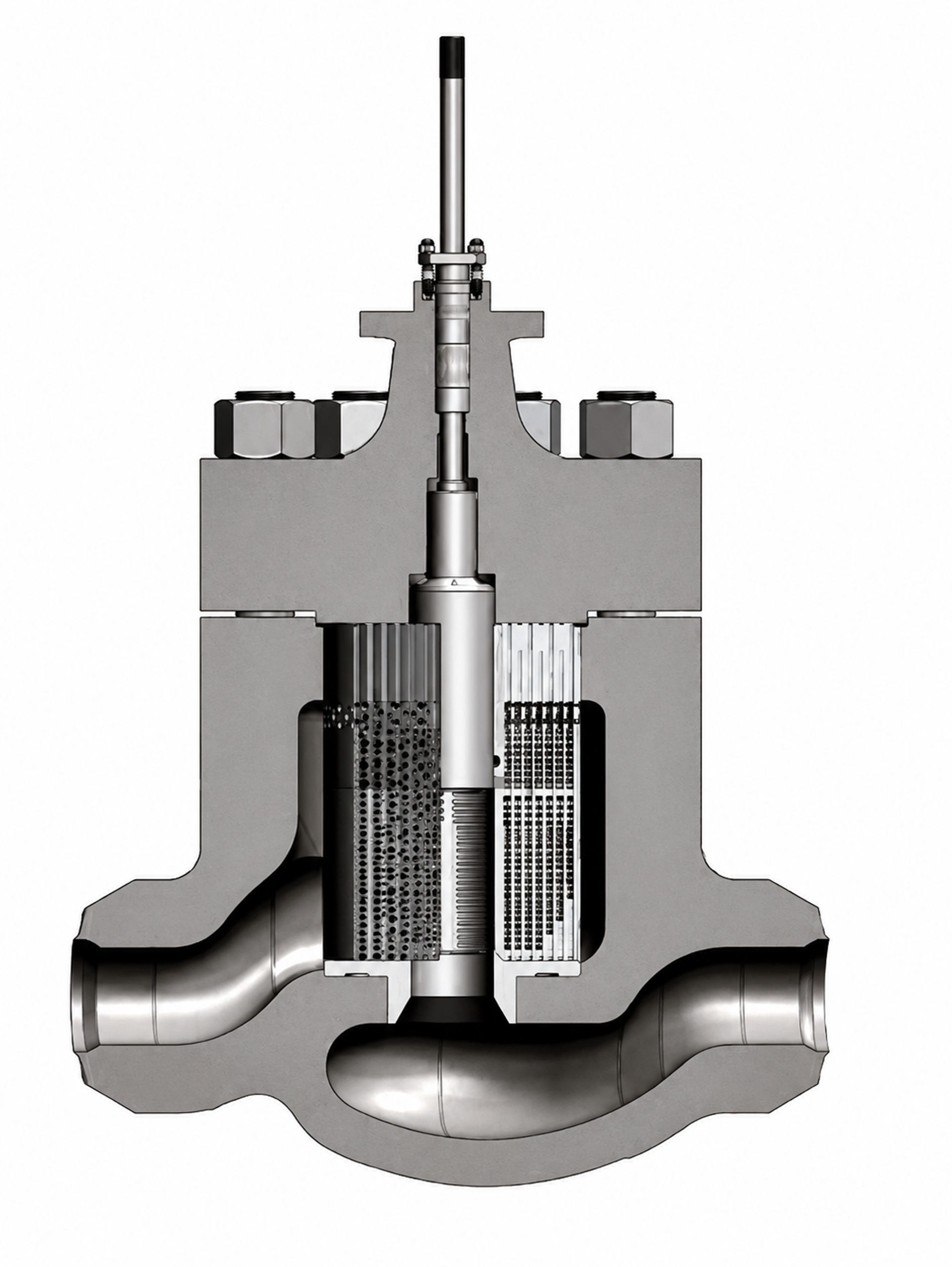
Figure 35. Cross-sectional view of the severe-service recirculation control valve trim and body.
Minimum-recirculation valves must pass the protective flow reliably when main-process demand is low. They may remain closed for long periods and then open against maximum pump head. Seat protection, rapid but stable actuation, debris tolerance, and vibration resistance are therefore critical. Startup-feed valves require high rangeability because pressure drop is high at low flow and decreases as boiler pressure rises. Spray-water valves require precise low-lift control without allowing the seat to become the principal throttling edge. [6-10, 15]
7.5 Oil, Gas, and Petrochemical Service
High-pressure liquid letdown, produced-water injection, wellhead injection, hydrocarbon recycle, pump bypass, and chemical injection can combine cavitation with sand, corrosion, gas breakout, viscosity effects, and remote installation. Refined hydrocarbons can exhibit damage potential comparable with water, whereas crude oils can respond differently because of multicomponent composition and particulate content. Vendor testing and material compatibility are essential. [10, 15]
Large-passage axial trims, dirty-service cages, and hardened or carbide components are commonly used in these services. Compact fine-passage disk stacks can be suitable for clean refined liquids but may plug in crude oil or produced water. The body geometry should direct the outlet jet away from the wall and provide adequate gallery volume. [9, 10, 15]
7.6 Chemical Injection and Very-Low-Flow Service
Very-low-flow-coefficient service is difficult because the controlling openings are small, contamination-sensitive, and exposed to a large fraction of the total pressure drop. MicroCav and low-coefficient ChannelStream trims place multistage grooves or cylinders in a closely guided plug head. Numbered cascade trims provide small repeatable coefficients through labyrinth grooves. Filtration, flushing, material compatibility, and a realistic minimum-flow specification are essential. [1, 2, 8]
7.7 Noise, Vibration, and Actuator Selection
A noise specification should identify the measurement location, operating case, pipe schedule, insulation, and whether the limit applies to predicted airborne sound, internal sound, or workplace exposure. A low external sound level does not demonstrate the absence of cavitation damage. Actuator sizing should include unbalanced hydraulic force, seal friction, packing, acceleration, fail action, and an adequate stability margin. Digital positioners can improve control resolution but cannot compensate for a mechanically unstable plug or an undersized actuator. [9, 10, 15, 20]