
Technical publication
Back to publications
Fundamentals
Physical Basis of Hydrodynamic Cavitation Generation
okozyuk.com
Published
Read complete publication for whole-document Find and printing. Browser Find and native printing on this reader include only loaded content.
2.3 Device Families
Hydrodynamic cavitators may be classified by the mechanism that creates the low pressure region. Figure 2.2 summarizes representative static and dynamic configurations. Orifice plates generate high speed jets and separated shear layers. Venturi devices accelerate and decelerate the flow more gradually, which can reduce irreversible losses relative to a sharp restriction. Multihole plates divide the flow into multiple jets and increase the number of simultaneous cavities. Vortex devices use tangential momentum to produce a low pressure core. Rotor stator systems combine rotational shear with rapid pressure fluctuations, while multistage baffles impose repeated cycles of acceleration and recovery. Contemporary studies of vortex based devices, continuous emulsification, and rotary cavitation illustrate the influence of geometry, scale up, and scale out on device performance [4,5,6].
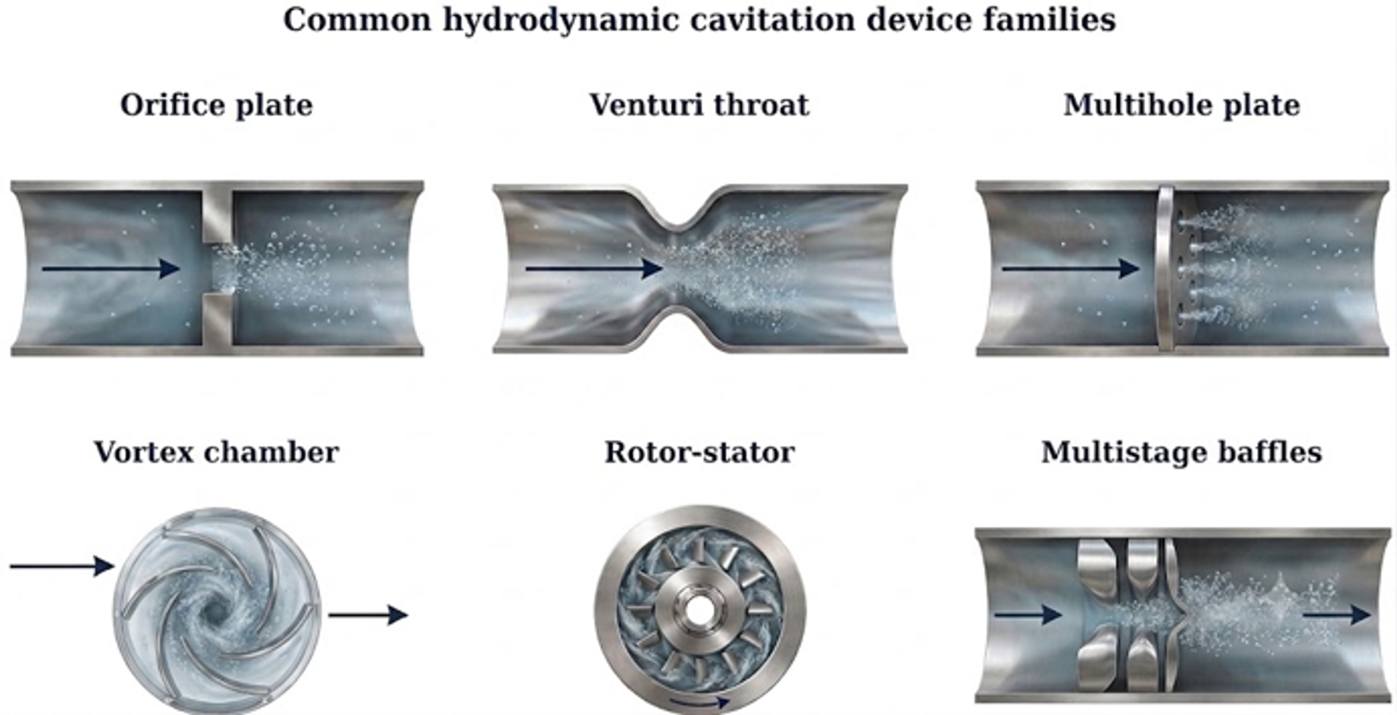
Figure 2.2. Common hydrodynamic cavitation device families. [7]
Table 2.1. Principal device characteristics and typical engineering implications.
| Device | Cavitation zone | Strengths | Main limitations |
|---|---|---|---|
| Single orifice | Jet vena contracta and downstream shear layer | Simple, compact, inexpensive, easy to characterize | High pressure loss; clogging risk; wall collapse and erosion if poorly designed |
| Multihole plate | Multiple jets and interacting cavity clouds | High event density; distributes flow; geometry is easily varied | Hole fouling; unequal flow distribution; manufacturing tolerances matter |
| Venturi | Throat and diffuser | Smoother acceleration; potentially lower irreversible loss | Longer device; cavity position depends strongly on diffuser and backpressure |
| Vortex chamber | Low pressure vortex core | Cavitation can occur away from walls; open flow passage; scale out is practical | Swirl stability and outlet geometry are critical; pressure measurements may not represent core pressure |
| Rotor or rotor stator | Rotor tip, gap, and wake regions | High throughput and strong mixing; tunable rotational speed | Moving parts, seals, mechanical wear, and more complex scale up |
| Multistage baffles | Repeated local restrictions | Multiple treatment zones in one body; adjustable designs are possible | Cumulative pressure loss and potential solids deposition |