
Technical publication
Back to publications
Reactors & equipment
Hydrodynamic Cavitation Technological Equipment
okozyuk.com
Published
Read complete publication for whole-document Find and printing. Browser Find and native printing on this reader include only loaded content.
4. Commercial Equipment
Commercial hydrodynamic cavitation equipment ranges from static, pump driven cavitation skids to rotating cavity rotor systems. Product names often combine the cavitation element with a proprietary process package that includes pumps, tanks, controls, heat exchangers, and application specific dosing. Capacity is fluid dependent because viscosity, gas, solids, temperature, and required pressure drop change both throughput and energy demand [10, 19-22, 26].
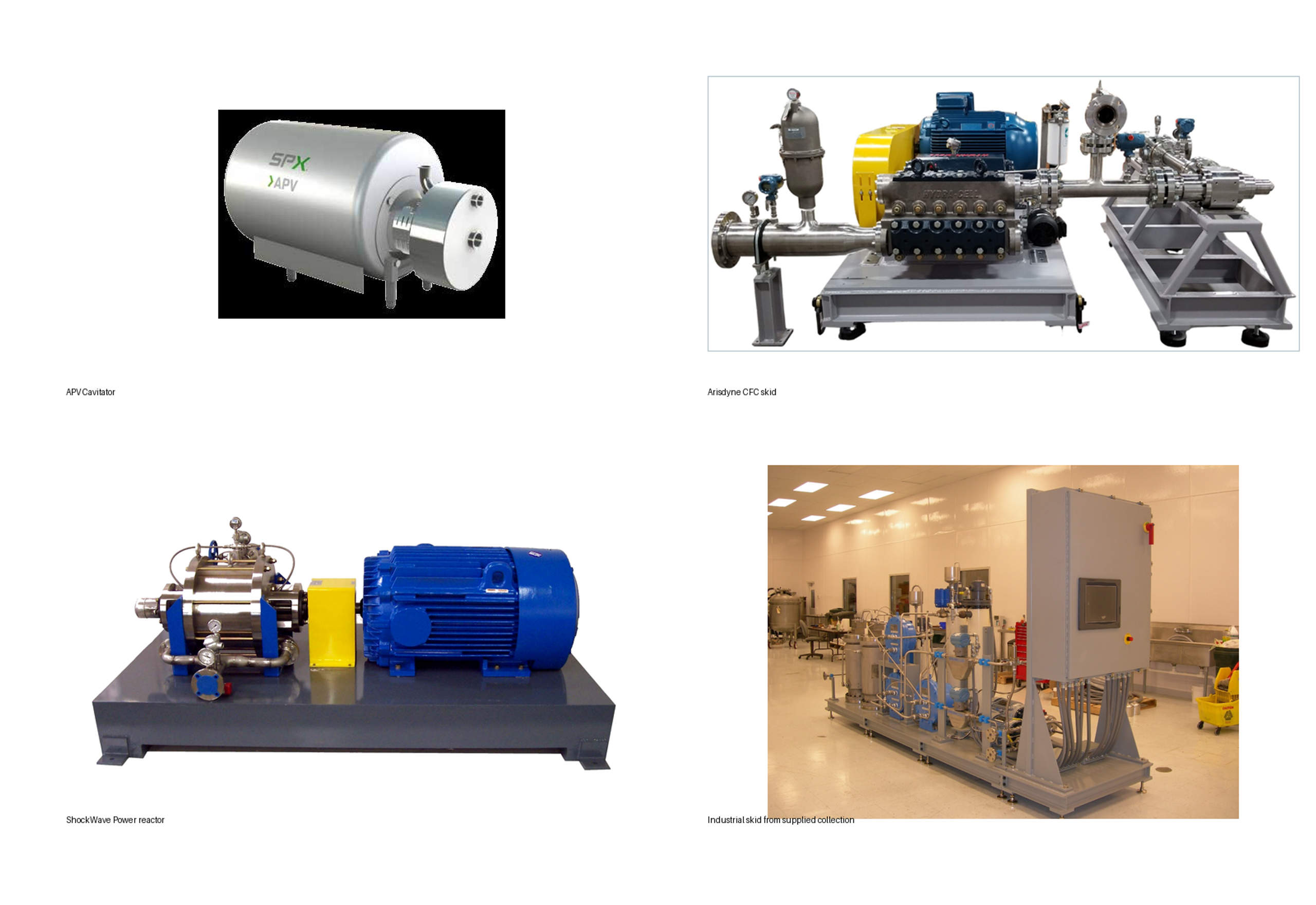
Figure 26. Representative commercial hydrodynamic cavitation equipment: APV cavity rotor processor, Arisdyne controlled flow cavitation skids, and Hydro Dynamics ShockWave Power Reactor [19-22, 26].
4.1 Historical and Laboratory Processors
The materials include historical Five Star Technologies Inc. CaviPro 300 and CaviMax processors and a collection of laboratory and pilot equipment photographs. These systems illustrate the recurring architecture of a cavitation package: a pressure source or rotor, an accessible treatment chamber, flow control, a small feed or hold vessel, and a rigid base. [10, 25, 27].
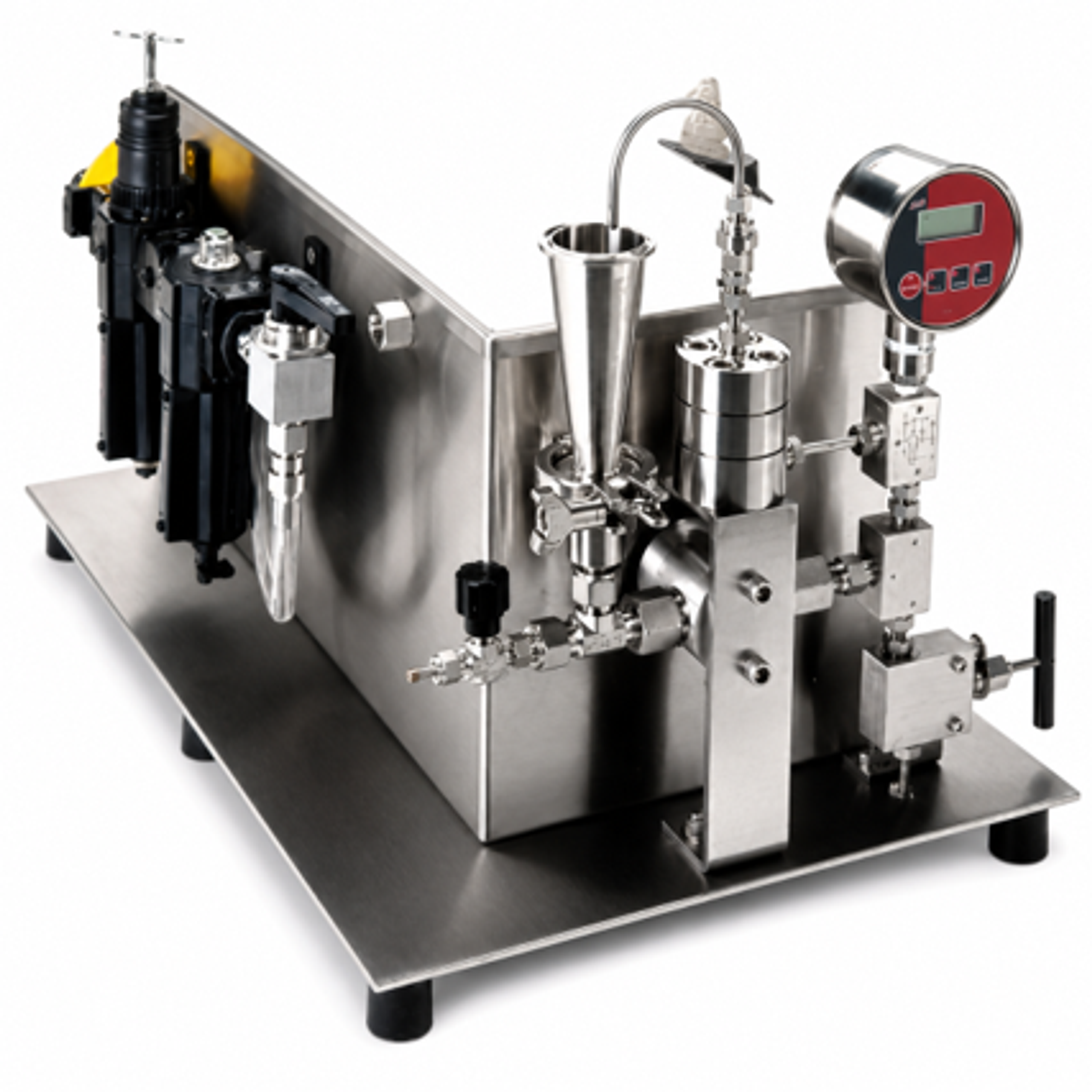
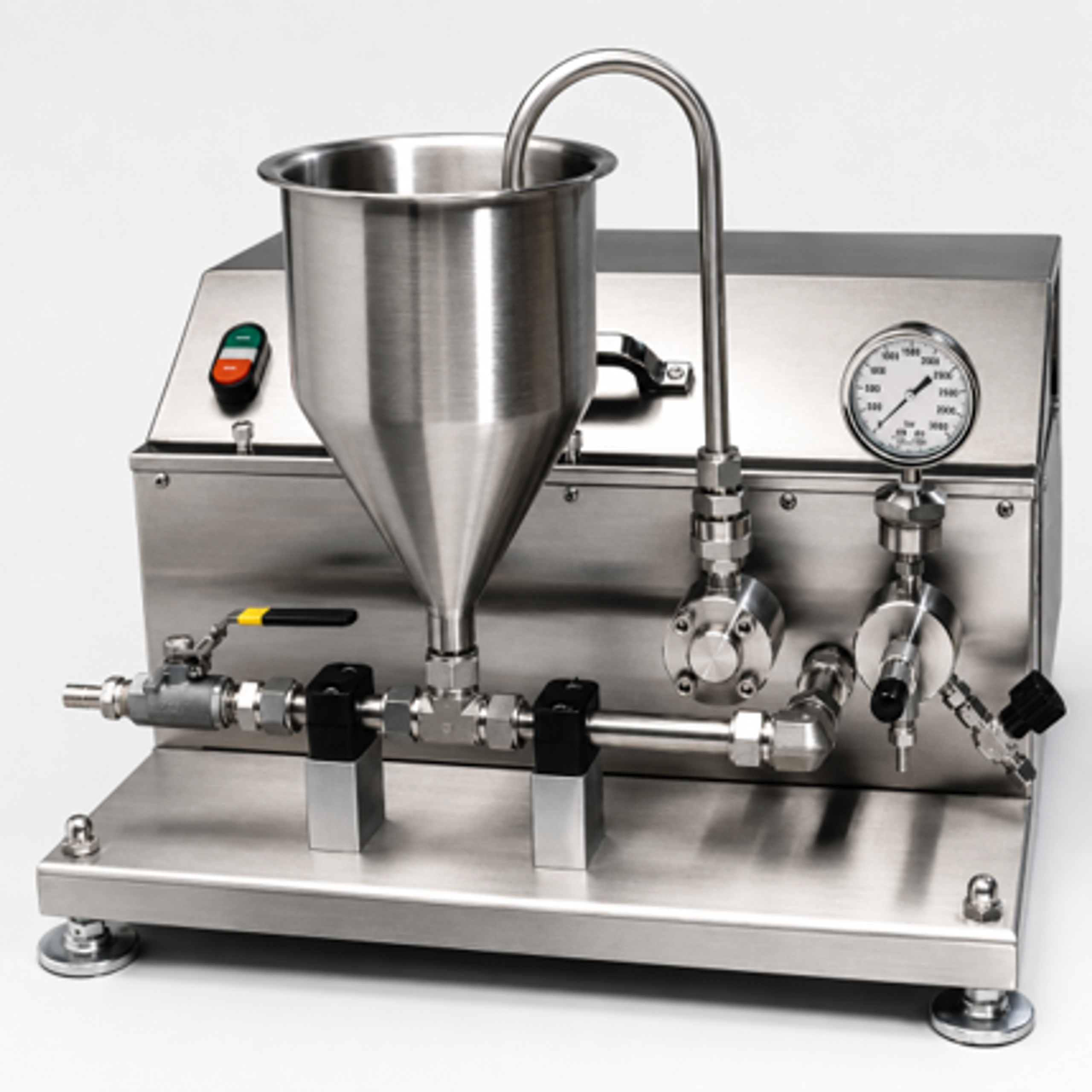
Figure 27. CaviPro 300 and CaviMax [10, 27].
4.2 APV Cavitator and Cavimaster Systems
SPX FLOW acquired the APV Cavitator technology through an exclusive global licensing agreement with Hydro Dynamics, Inc.
The APV Cavitator is a sanitary dynamic system based on a rotor containing multiple rows of holes. The SPX brochure lists four rotor sizes, nominally 200, 305, 355, and 406 mm, with two, three, or four rows of holes, product contact construction in AISI 316L stainless steel, sanitary clean in place design, and application dependent capacity up to 20,000 L/h. [19]. The current official product page continues to present the Cavitator as a controlled cavitation mixer for microscopic integration, emulsification, hydration, gas liquid mixing, and internal heating, while the Cavimaster system combines indirect preheating, cavitational processing, and cooling for dairy protein functionality [26, 37].
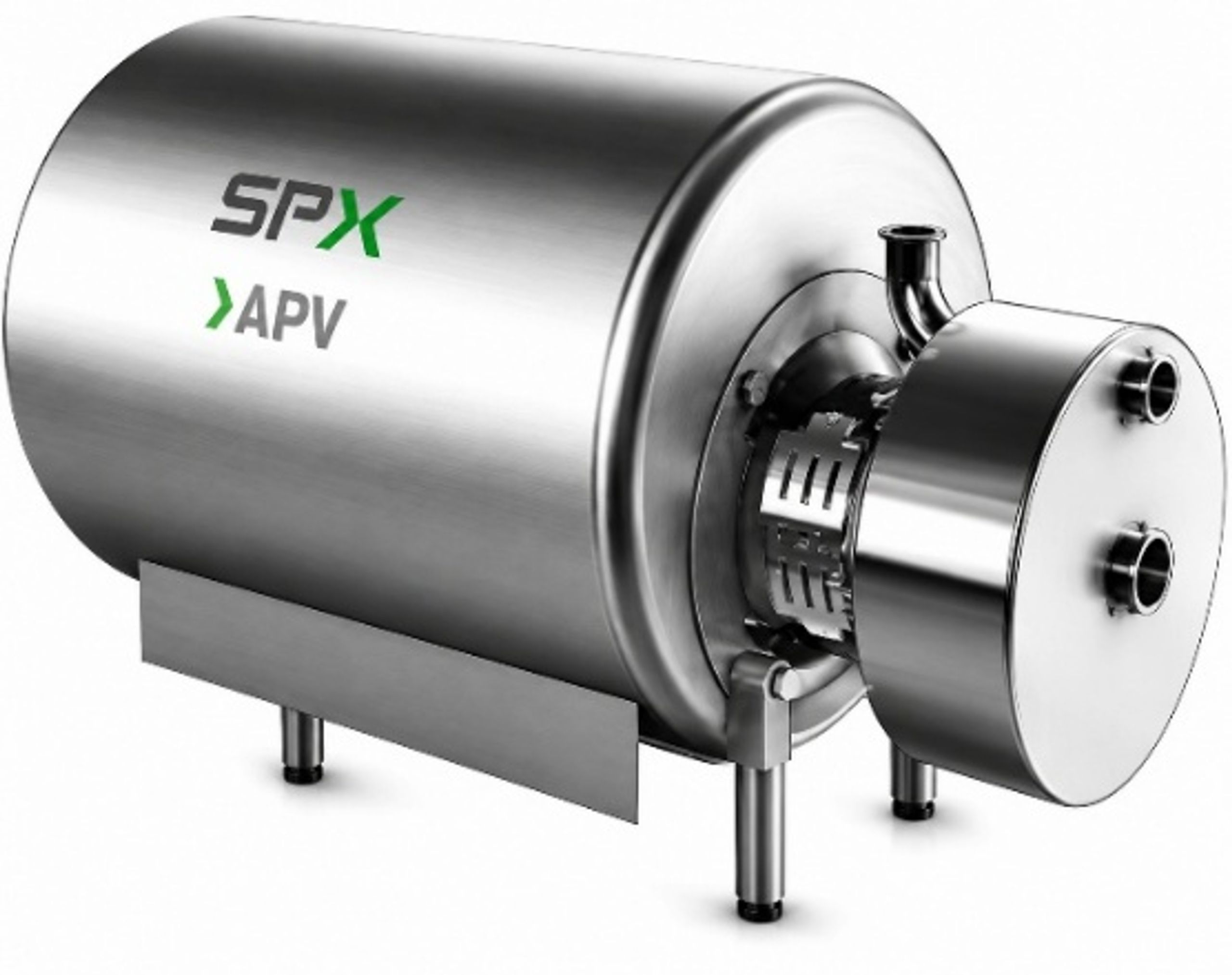
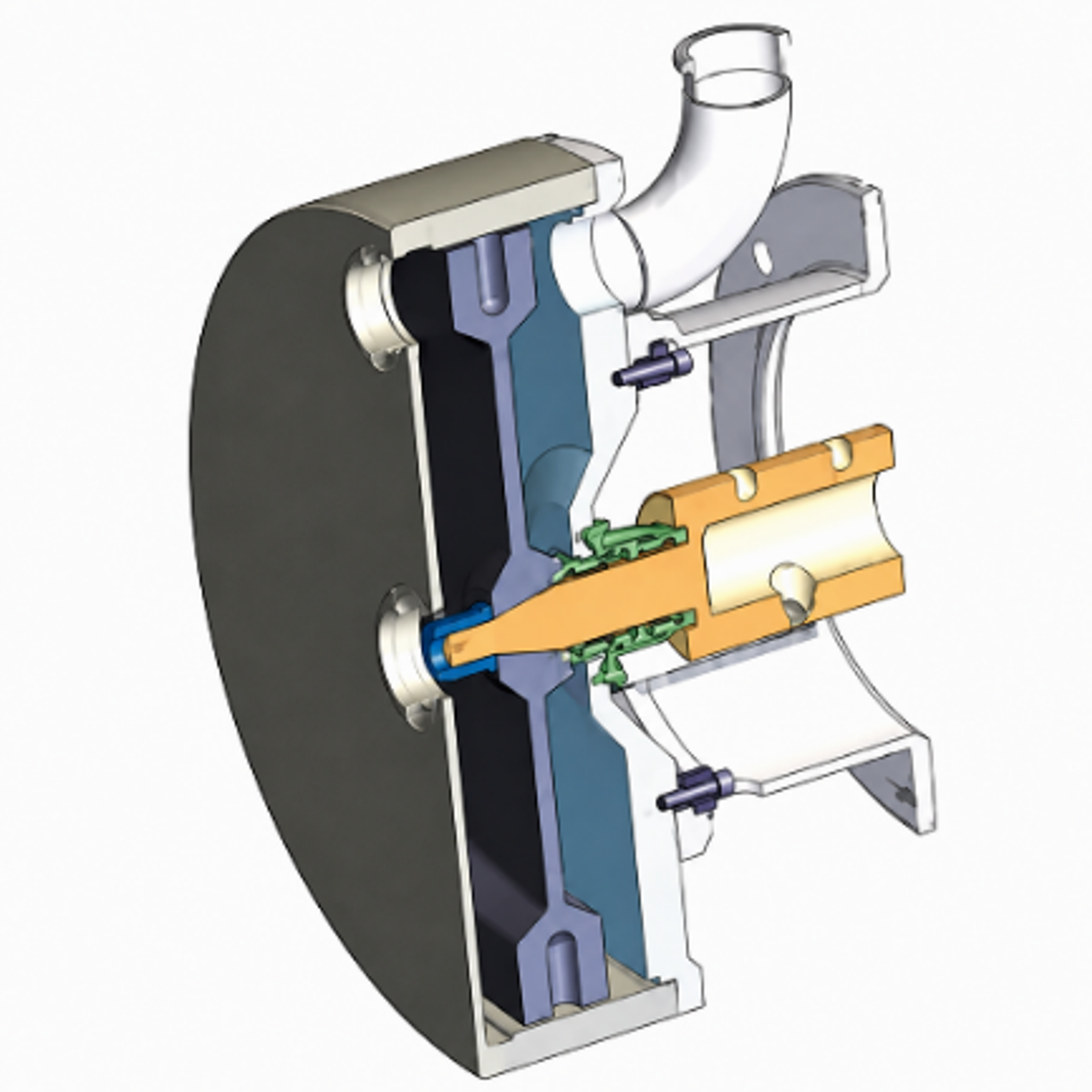
Figure 28. APV Cavitator exterior and cutaway [19].
A sanitary procurement specification for this type of machine should include rotor configuration, motor rating and speed range, seal materials, elastomer grade, maximum inlet and outlet pressure, allowable gas fraction, particle size limit, clean in place velocity, drainability, surface finish, and validation protocol. Because product temperature may rise through motor energy dissipation, cooling capacity and temperature control logic must be defined even when heating is not the primary duty. Vendor reported scale free heating should be evaluated using the actual fouling product, run duration, temperature program, and post run surface inspection [19, 26].
4.3 ShockWave Power Reactor
Hydro Dynamics, Inc. (HDI) is a specialized industrial technology company headquartered in Rome, Georgia, best known as the developer and manufacturer of the patented ShockWave Power Reactor (SPR). Founded in 1991, the company developed a method to safely harness hydrodynamic cavitation.
Hydro Dynamics markets the ShockWave Power Reactor as a cavity rotor system for mixing, extraction, and surface free heating. Current vendor material lists a laboratory package with a 304 stainless steel reactor, variable frequency drive, maximum pressure of 150 psig, and a reported flow range of 0.1 to 7.5 gal/min. The same product line lists an industrial package with application dependent flow up to 1,500 gal/min and a sanitary package up to 150 gal/min. These are vendor specifications and must be confirmed for the selected rotor, fluid, pressure, temperature, and treatment objective [20, 22].
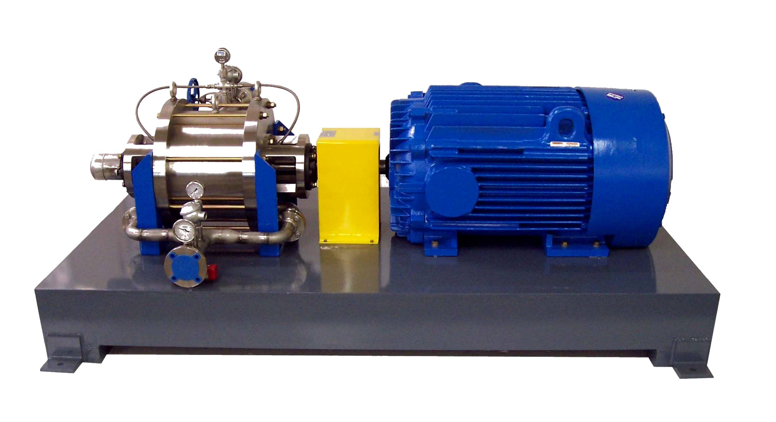
Figure 29. ShockWave Power Reactor [20, 22].
4.4 Arisdyne Controlled Flow Cavitation Systems
Arisdyne Systems, Inc. is a biotechnology and industrial equipment company specializing in patented hydrodynamic cavitation technologies. Founded in 2006 and headquartered in Middleburg Heights, Ohio, the company designs retrofit equipment intended to increase process yields and reduce chemical costs in alternative fuel and industrial fluid processing.
Arisdyne markets controlled flow cavitation as a static device with no moving parts in the cavitation element. Technical material emphasizes mass transfer between liquid phases, biodiesel, vegetable oil, ethanol, and other process intensification duties. Arisdyne reports 100 machines sold worldwide, nominal capacities from 150 to 1,750 metric tons per day, and an application specific energy claim of 2.5 kWh per metric ton. These figures are not universal equipment constants; they depend on feedstock, reaction chemistry, target conversion, pump efficiency, and the declared plant boundary. [21].
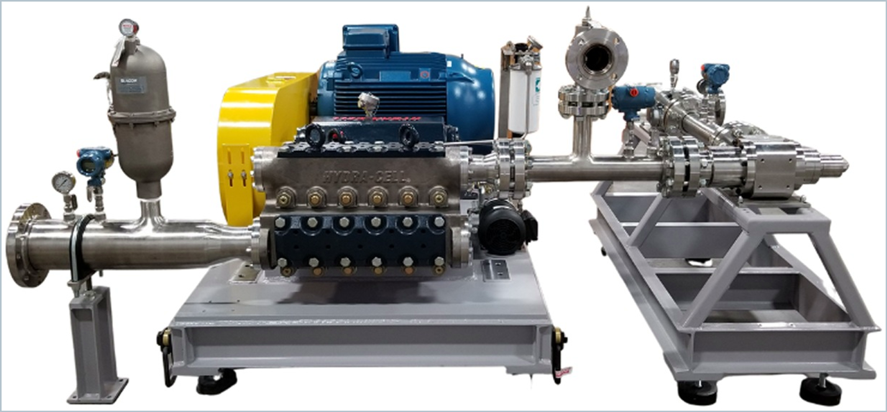
Figure 30. Arisdyne controlled flow cavitation processing skid with feed pump, pressure control, and cavitation section [21].
Arisdyne manufactures several hydrodynamic cavitation homogenizers designed for the efficient mixing and homogenization of liquids using the principles of hydrodynamic cavitation.
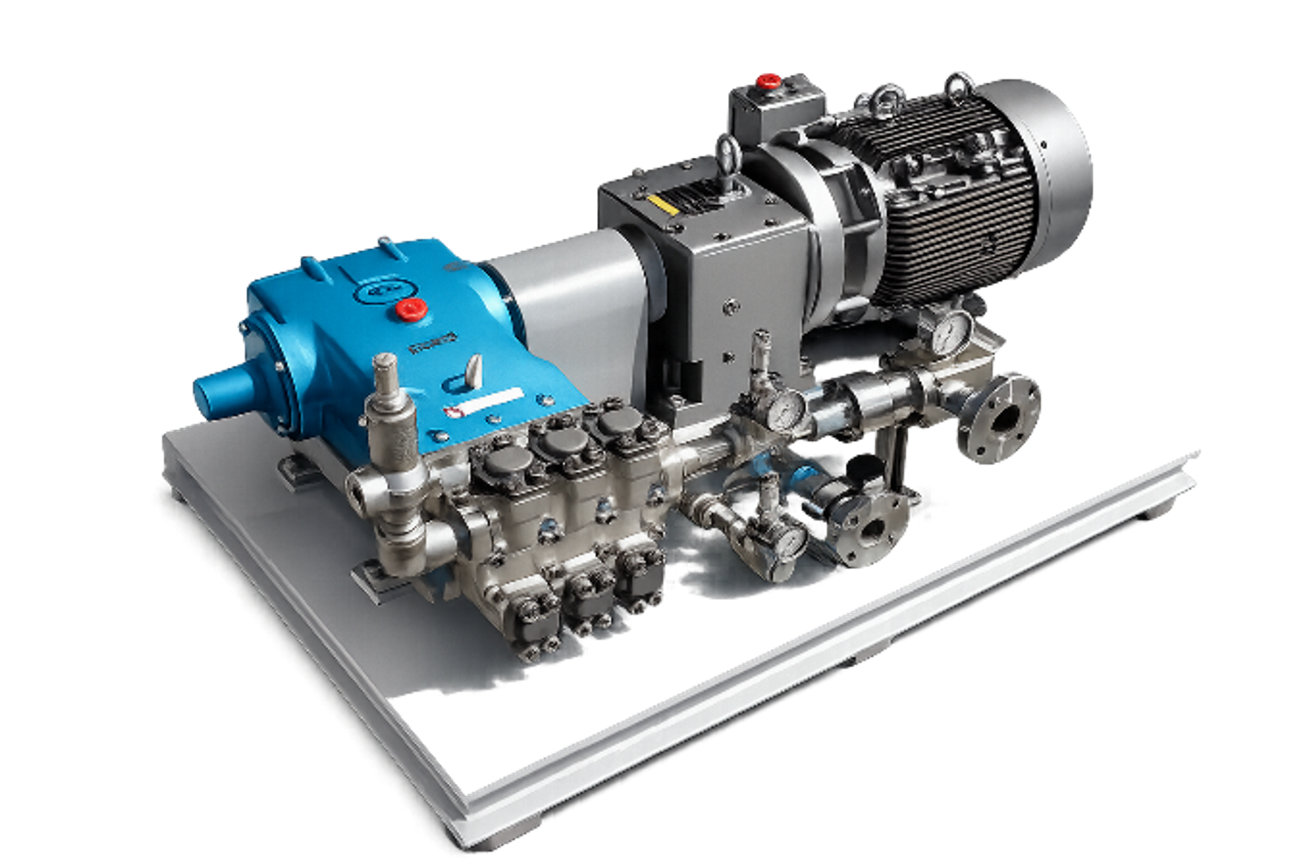
Figure 31. Arisdyne skid configurations homogenizers 8 GPM [27].
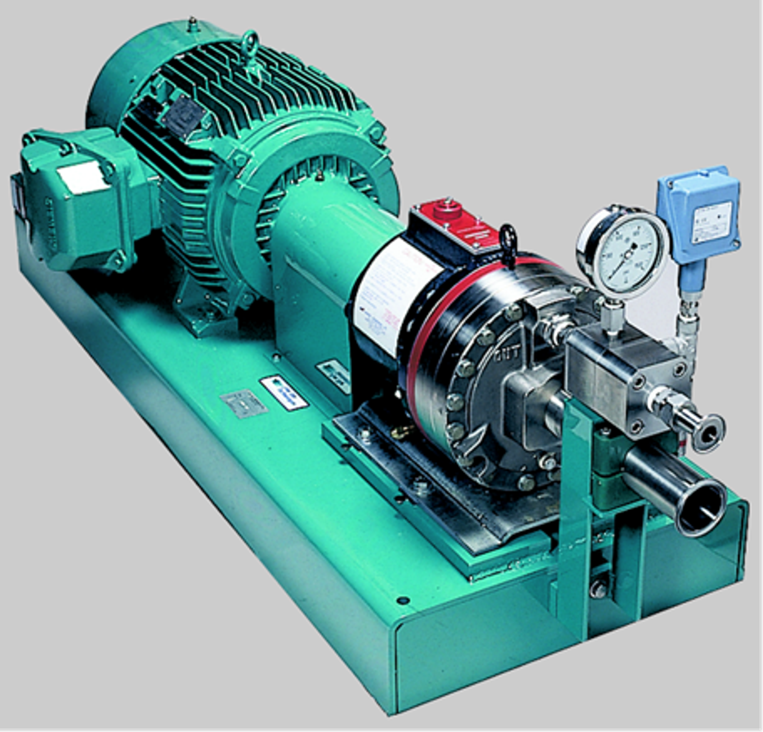
Figure 32. Arisdyne skid configurations homogenizers 30 GPM [27].
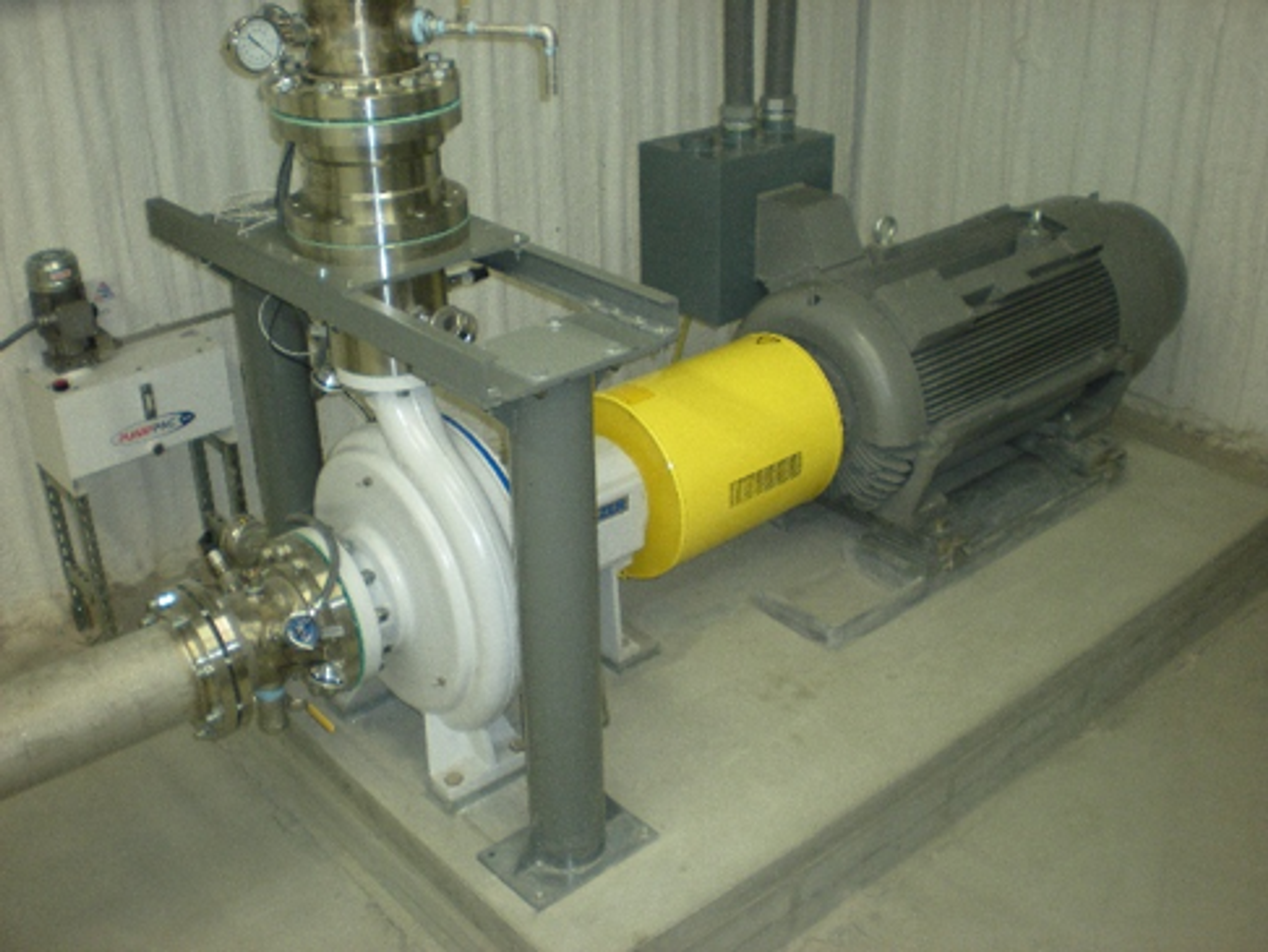
Figure 33. Arisdyne production cavitation skids illustrating 800 GPM [27].
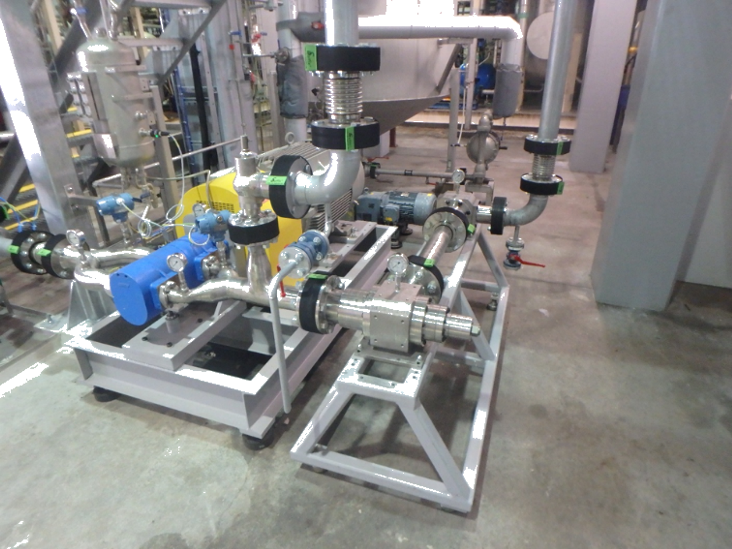
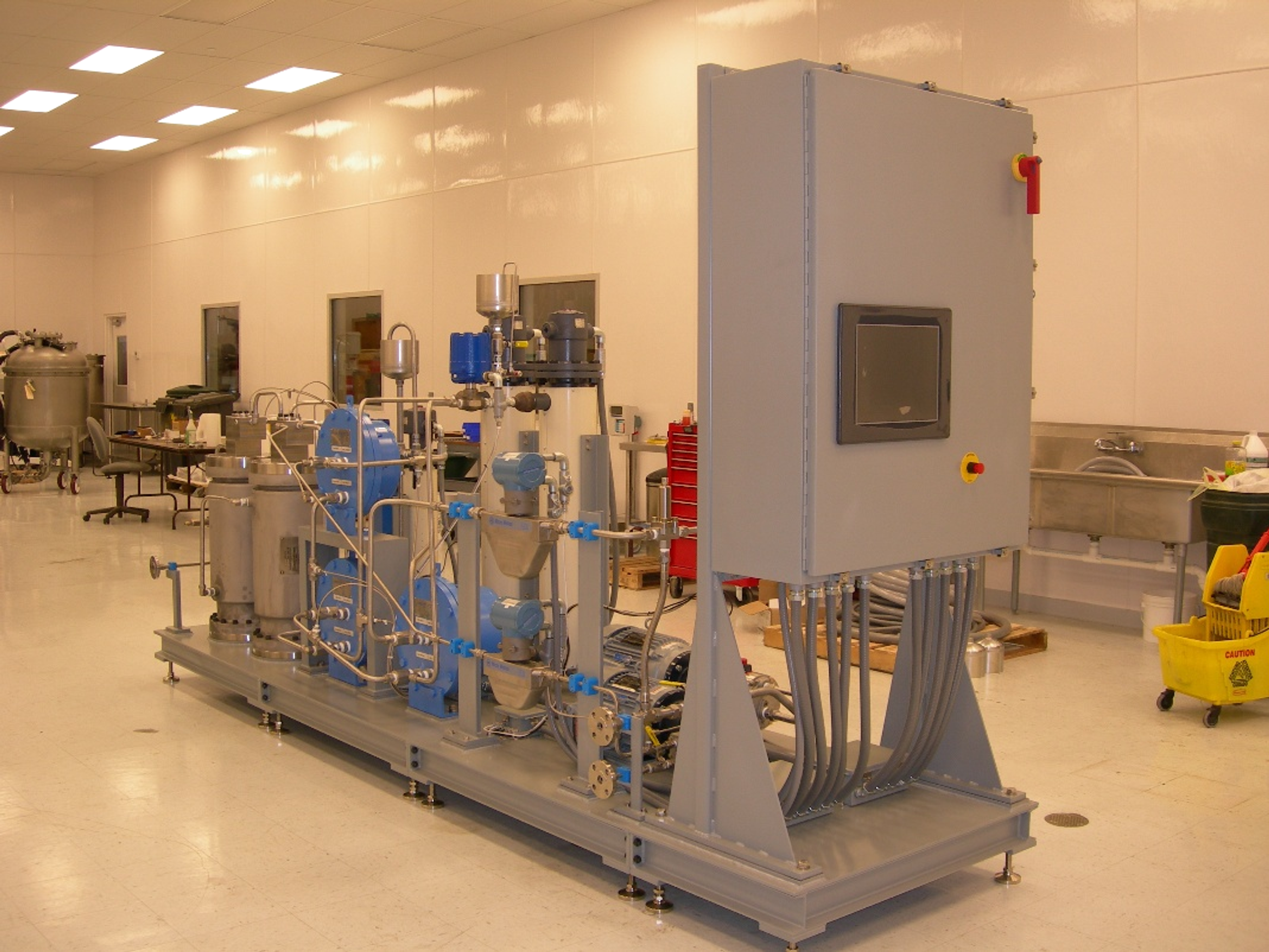
Figure 34. Arisdyne production cavitation skids illustrating industrial integration, rigid supports, valves, tanks, and control panels [27].
4.5 CTI Nano Reactor and CaviTune LPN Systems
Cavitation Technologies, Inc. (CTI) is a specialty industrial machinery corporation that designs, manufactures, and patents commercial hydrodynamic cavitation systems. The company was founded in 2007 and is headquartered in Chatsworth, California.
The supplied Cavitation Technologies material shows static inline Nano Reactor bodies, complete Nano Neutralization skids, and the CaviTune Low Pressure Nano Reactor package. The equipment architecture uses a pump, pressure control components, an inline multistage body, and rigid stainless steel piping on a common base. CTI reported a flow range of approximately 18.9 to 416 L/min, operating pressure from about 15 to 20 bar, 316 stainless steel construction, and recommended upstream filtration of 40 μm for nonabrasive material [34, 35].
Table 9. CaviTune Low Pressure Nano Reactor models reported in supplied promotional literature [34].
| MODEL-5 | MODEL-50 | MODEL-110 |
|---|---|---|
| Pressure, 290 psi (20 bar) | Pressure, 290 psi (20 bar) | Pressure, 290 psi (20 bar) |
| Flow Min., 5 GPM (18.9 liter/minute) | Flow Min., 10 GPM (37.8 liter/minute) | Flow Min., 50 GPM (189 liter/minute) |
| Flow Max. 15 GPM (56.8 liter/minute) | Flow Max., 50 GPM (189 liter/minute) | Flow Max., 110 GPM (416 liter/minute) |
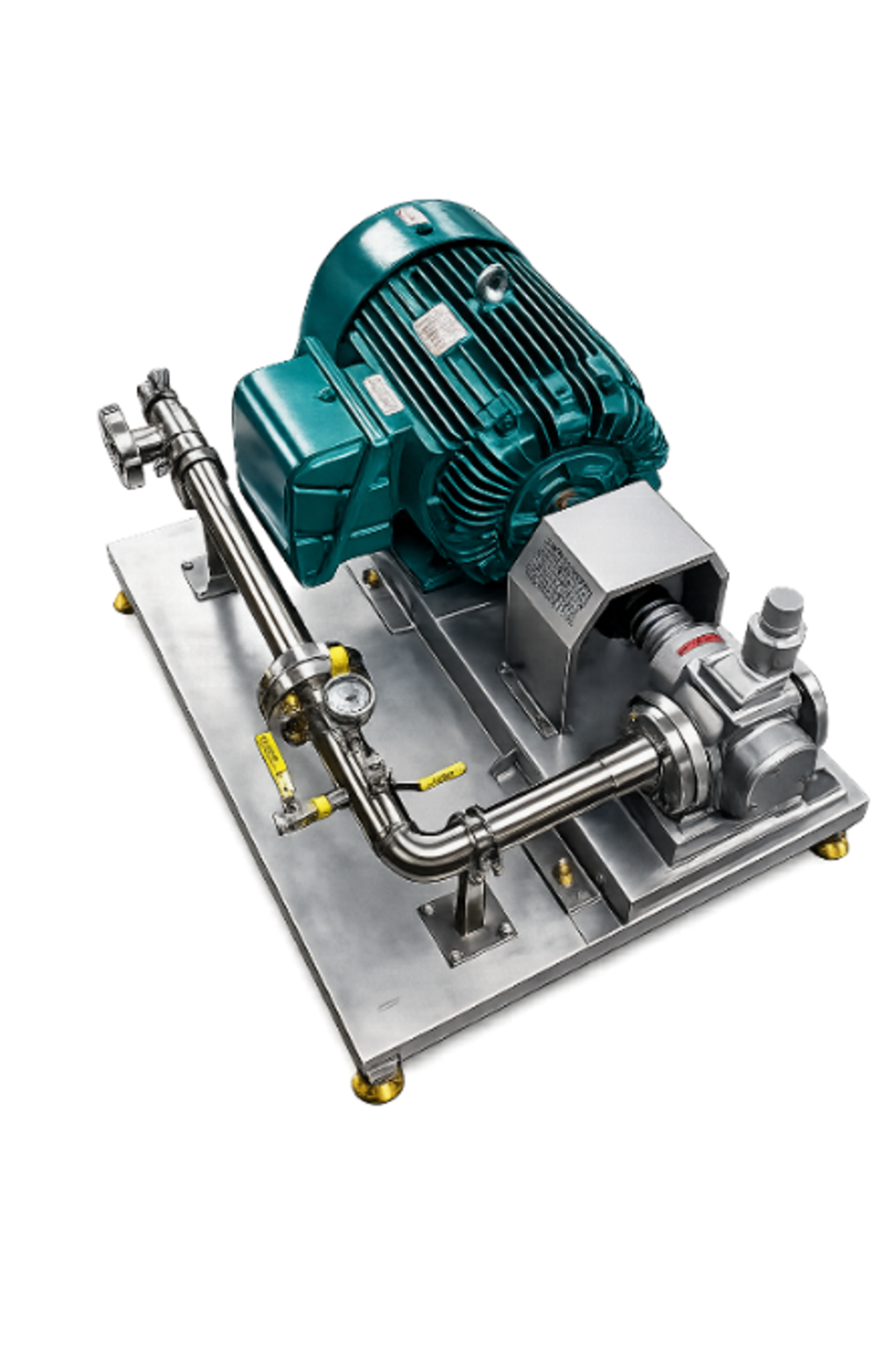
Figure 35. CaviTune Super Mixer Low Pressure Nano Reactor skid [34].
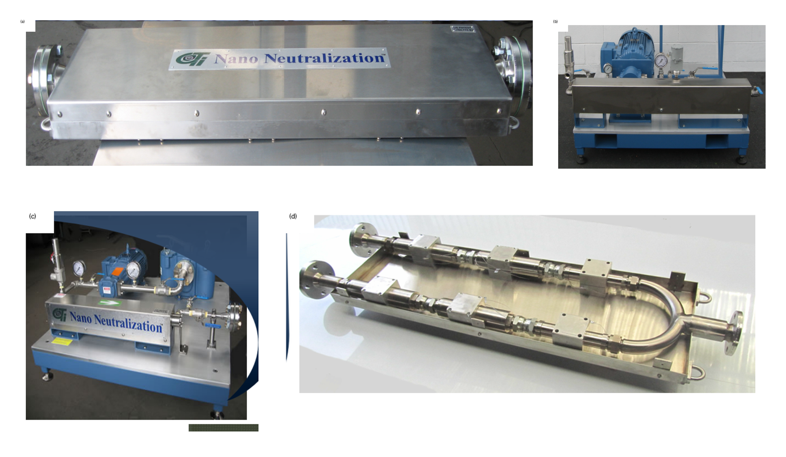
Figure 36. CTI Nano Reactor bodies and Nano Neutralization skid configurations [35].
A 2025 company filing states that the Nano Reactor and LPN were the critical components of the company's historical systems and reports that more than 200 systems had been shipped domestically and internationally. [36]. For procurement, the reactor should be specified together with the pressure source curve, bypass and relief arrangement, filtration duty, stage count, cleanability, pressure rating, corrosion allowance, and a product guarantee measured at the skid electrical disconnect.
Table 10. Selected commercial equipment and procurement considerations. Capacities and benefits are vendor reported unless independently identified.
| System | Cavitation element | Published or supplied information | Procurement verification |
|---|---|---|---|
| APV Cavitator / Cavimaster [19,26,37] | Dynamic rotor with rows of holes | Sanitary 316L construction; several rotor sizes; brochure capacity up to 20,000 L/h; mixing and internal heating. | Product specific capacity, temperature rise, cleanability, particle limit, seal life, and motor power. |
| ShockWave Power Reactor [20,22] | Dynamic rotor with dead ended cavities | Laboratory skid and large flow reactors; mixing, extraction, and heating applications. | Rotor and housing material, actual flow pressure speed map, energy boundary, erosion inspection, and noise/vibration. |
| Arisdyne CFC [21] | Static controlled flow cavitation device | No moving parts in cavitation element; commercial process skids; vendor throughput and energy claims. | Pump power, pressure drop, solids tolerance, pressure pulsation limits, conversion guarantee, and spare element strategy. |
| Historical CaviPro/CaviMax [10,27] | High pressure or controlled cavitation processors | Photographic documentation of laboratory equipment and process architecture. | Current support, pressure rating, parts availability, and regulatory status. |
| Custom research or pilot skid [27] | Interchangeable static or dynamic element | Flexible geometry and modular hardware for development and scale up. | Uncertainty, containment, repeatability, operating envelope, and documented change control. |
| CTI Nano Reactor / CaviTune LPN [34–36] | Static multistage inline cavitation body | Supplied brochure shows skid and inline systems; vendor envelope approximately 38-510 L/min and 52-75.8 bar; company reports more than 200 systems shipped. | Fluid specific pressure flow curve, filtration and solids limit, stage pressure map, pressure rating, cleanability, electrical SEC, and product guarantee. |
4.6 Microfluidics Microfluidizer Processors and Impinging Cavitating Jets
4.6.1 Corporate and Equipment Context
Microfluidics manufactures Microfluidizer processors within IDEX Material Processing Technologies. The current company history states that Microfluidics joined IDEX in 2011. The equipment family spans benchtop, pilot, and production processors, but the common process architecture is a pressure intensifier, a fixed geometry interaction chamber, product cooling, and either collection or recirculation [38, 39, 42, 44, 45].
The engineering classification is high pressure fixed geometry homogenization. The interaction chamber imposes very high velocity gradients, abrupt changes in direction, turbulence, cavitation, jet impact, and a rapid pressure decrease followed by recovery. Depending on chamber geometry, inlet pressure, downstream pressure, liquid vapor pressure, dissolved gas, and viscosity, hydrodynamic cavitation can occur in the accelerated microchannels and in the low pressure region before or during jet impingement. Microfluidics patents explicitly identify high shear, impact, and cavitation as interacting mechanisms in chamber designs [46-48].
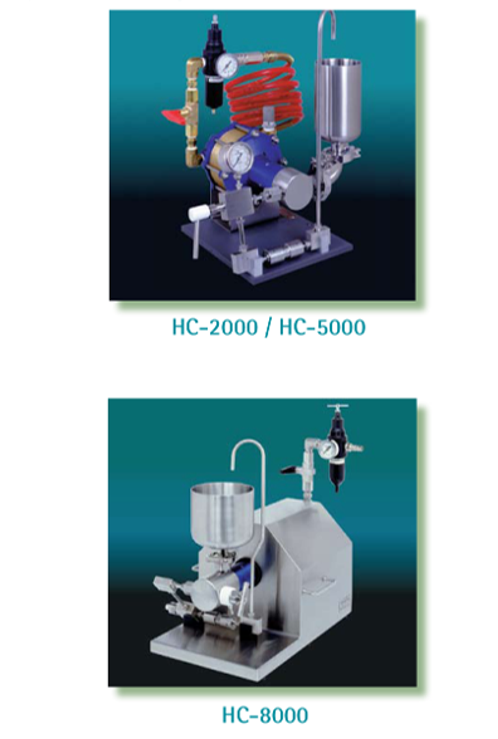
Figure 37. Microfluidics HC 2000, HC 5000, and HC 8000 laboratory homogenizers [38].
4.6.2 Impinging Jet Interaction Chamber Mechanism
In a Y type chamber, a pressurized product stream is divided into two or more microchannels. The streams accelerate and meet at a controlled interaction region. The collision converts organized jet momentum into rapidly fluctuating pressure, small scale turbulence, extensional strain, and local impact. When the static pressure in the accelerating channels or expanding jet falls below the effective inception pressure, cavitation develop. Pressure recovery in the interaction zone and downstream passage then drives collapse. A Z type chamber uses a single tortuous path and strong direction changes, while an auxiliary processing module can provide a larger initial passage for pre dispersion or protection of a smaller downstream chamber [40, 44].
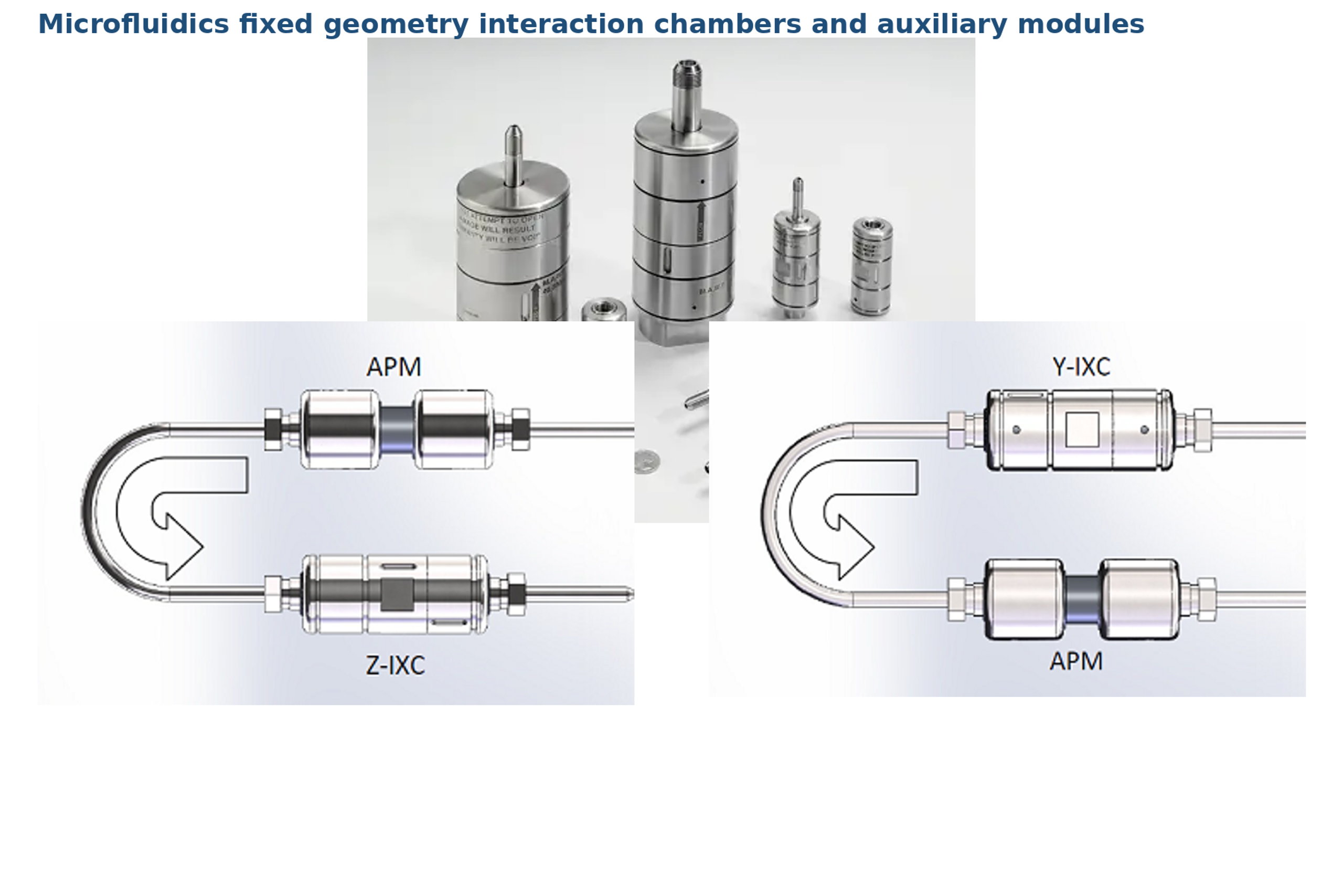
Figure 38. Microfluidics fixed geometry interaction chambers, Y type and Z type flow paths, and auxiliary processing module configurations [44].
Existing technical literature cites characteristic dimensions for microchannels (approximately 50 to 400 µm) and specifies the materials used for their fabrication: aluminum oxide or polycrystalline diamond. Schematics are also provided for a single slot Y type chamber and a multi slot variant used for process scale up. These figures pertain to specific chamber models and should not be regarded as universal specifications applicable to all existing models [40].
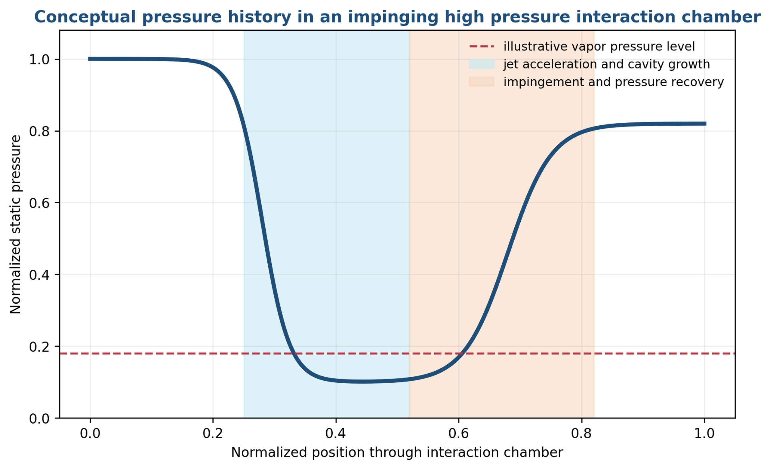
Figure 39. Conceptual pressure history in an impinging high pressure interaction chamber [46-48].
4.6.3 Hydraulic Analysis of the High Pressure Jet
A first estimate of jet velocity is obtained by applying a velocity coefficient to the pressure energy available across the chamber:
where vj is characteristic jet velocity and Cv includes contraction and loss effects. The ideal velocity can be several hundred meters per second at the highest pressures, but the actual local velocity depends on chamber area, fluid compressibility, vapor formation, and multiphase choking. Reports indicate microchannel velocities approaching 500 m/s for selected conditions [40].
The hydraulic energy made available per unit mass is:
The corresponding kinetic power scale carried by a jet is:
If pressure energy is ultimately retained as sensible heat, an adiabatic temperature rise estimate is:
At 100 MPa, Equation (24) gives an ideal rise of about 24 K for water before accounting for pump efficiency, heat transfer, metal heat capacity, vaporization, and the fact that part of the pressure may remain at the outlet. This is why a cooling coil or heat exchanger is integral to most laboratory and production Microfluidizer systems. The short active residence time limits exposure, but repeated passes can accumulate heat [39, 42, 44].
4.6.4 Equipment Range and Scale Continuity
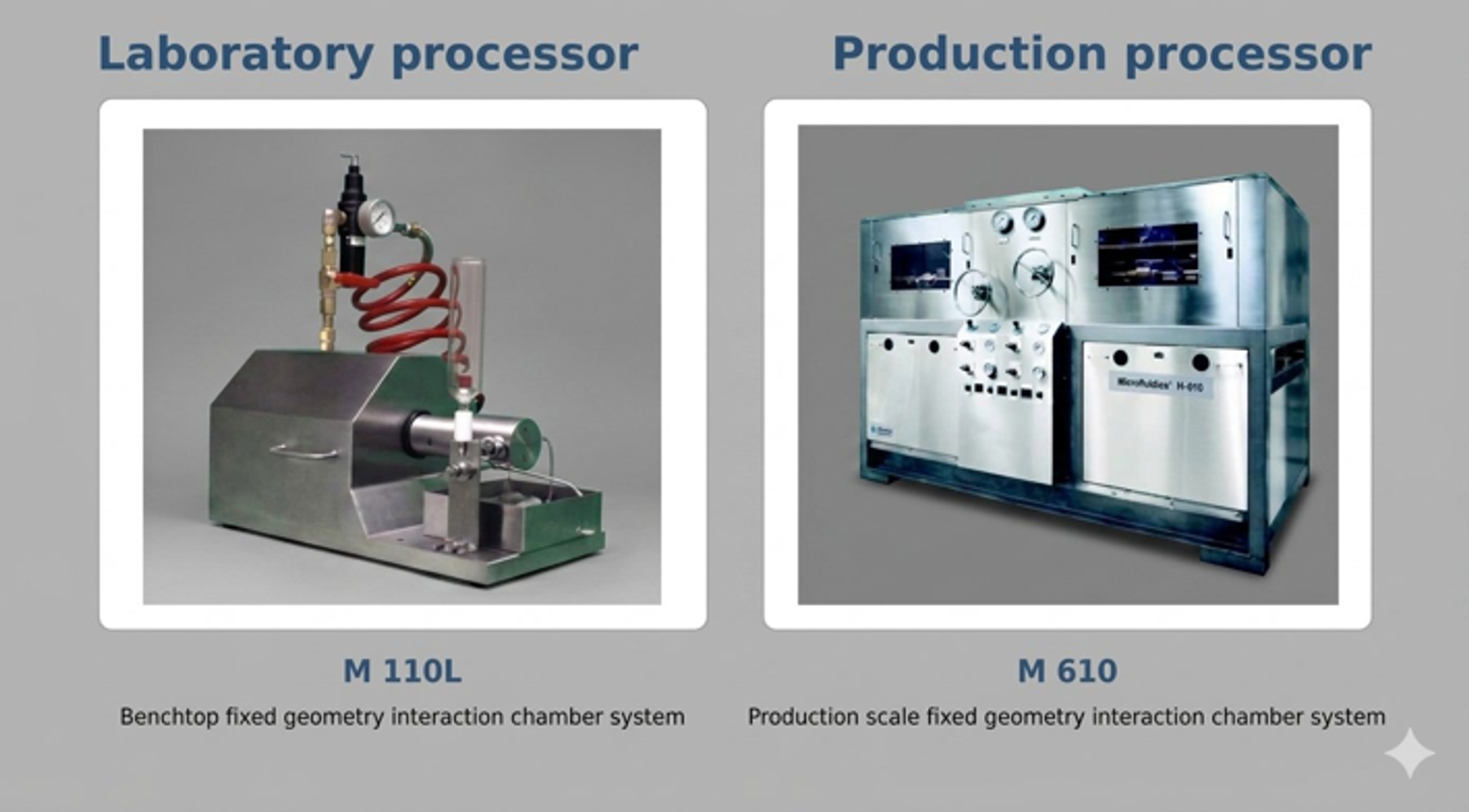
Figure 40. Laboratory M 110L and production M 610 Microfluidizer processors [39, 42].
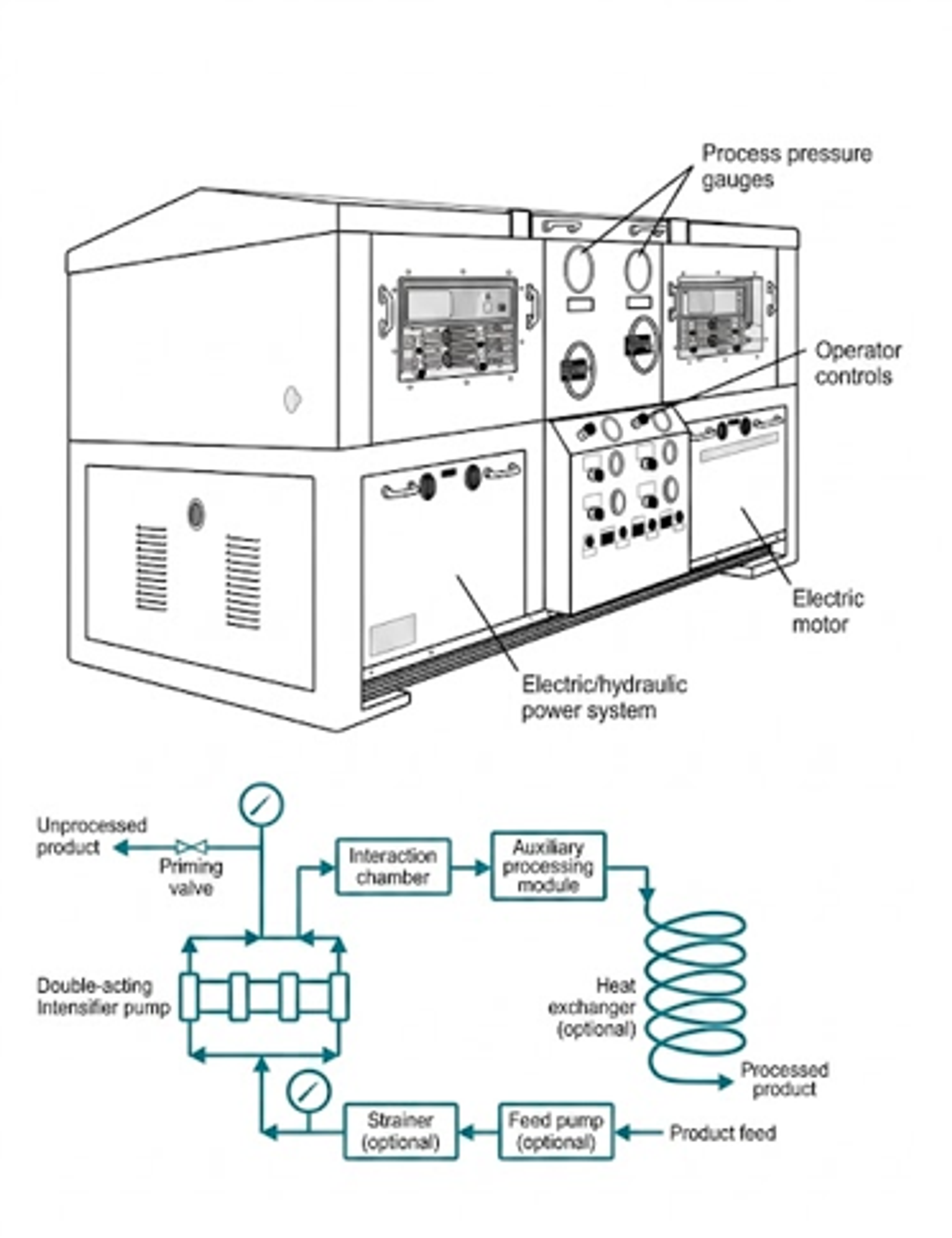
Figure 41. M 610 production processor operating principle, including intensifier pump, interaction chamber, auxiliary processing module, and optional heat exchanger [42].
Table 11. Selected Microfluidics processor ranges.
| Processor | Scale and drive | Pressure range | Nominal flow or sample range | Source |
|---|---|---|---|---|
| HC 2000 | Legacy laboratory pneumatic | 250 to 2,000 psi | Up to 2.0 L/min; 100 mL to continuous | [38] |
| HC 5000 | Legacy laboratory pneumatic | 500 to 5,000 psi | Up to 0.95 L/min; 100 mL to continuous | [38] |
| HC 8000 | Legacy laboratory pneumatic | 1,000 to 8,000 psi | Up to 1.0 L/min; 250 mL to continuous | [38] |
| M 110L | Legacy laboratory pneumatic | 3,000 to 18,000 psi | Up to 0.27 L/min; minimum 14 mL | [39] |
| M 110P | Current benchtop electric hydraulic | Up to 30,000 psi | Up to about 0.12 L/min; small laboratory batches | [44] |
| M 815 | Current pilot electric hydraulic | Up to 30,000 psi | About 1.0 to 1.2 L/min | [44] |
| M 610 | Legacy custom production electric hydraulic | Up to 40,000 psi | Custom; literature reports up to 18 gpm, about 68 L/min | [42] |
The essential scale up principle is preservation of the fixed local chamber geometry and pressure condition while increasing the number of parallel slots or installing additional chambers and intensifier capacity. An engineering scale up should nevertheless verify branch flow balance, pressure pulsation, temperature, product residence time, chamber wear, and the full particle or droplet distribution [40, 42].
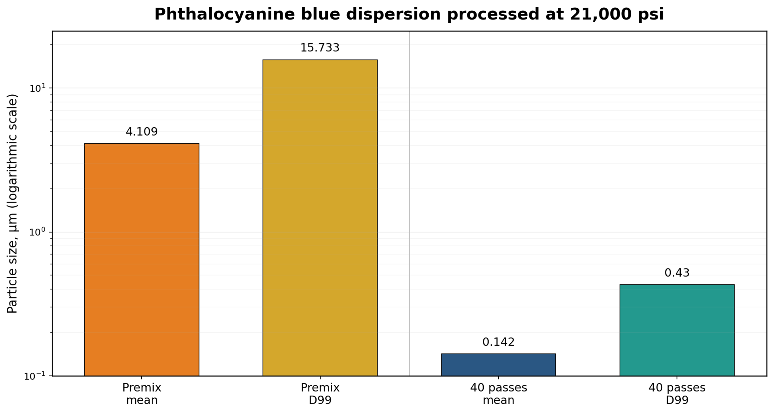
Figure 42. Phthalocyanine blue pigment size reduction reconstructed from Microfluidics data. The graph uses the reported mean and D99 values before processing and after forty passes at 21,000 psi [41].
Table 12. Representative Microfluidizer results from different materials.
| Product | Pressure and passes | Reported result | Source |
|---|---|---|---|
| Liposomes with dye marker | 4,000 psi; one to four passes | About 300 to 400 nm after one pass; subsequent passes tightened the distribution | [38] |
| Soy milk | 4,000 psi; one pass | Mean particle size reduced from 0.76 to 0.40 μm | [38] |
| E. coli suspension | 5,000 psi; three passes | About 90 percent rupture | [38] |
| Phthalocyanine blue dispersion | 21,000 psi; forty passes | Mean size 4.109 to 0.142 μm; D99 15.733 to 0.43 μm | [41] |
| Algae in water | 22,000 psi; two passes | 98 percent cell rupture | [43] |
| Oil in water emulsion | 10,000 psi; one pass | Vendor reported 175 nm average with narrow distribution | [42] |
| E. coli production example | 11,000 psi; one pass | More than 90 percent rupture at 30 gal/h while maintained near 15 °C | [42] |
The pigment result demonstrates that a high final pass count can be required for a difficult agglomerated solid even when the chamber pressure is high. The algae result demonstrates rapid cell disruption under another formulation. For a new process, the equipment should be evaluated using a matrix of pressure and pass count with replicate sampling, particle size distribution, microscopy where appropriate, temperature history, and specific electrical energy.
4.6.5 Engineering Cautions and Qualification
A fixed geometry chamber improves reproducibility only when the feed reaches the chamber in a stable condition. Entrained gas can compress in the intensifier, interrupt check valve operation, and alter cavitation. Oversized particles or fibers can block the smallest passage. Abrasive solids can change the chamber geometry and introduce wear debris. High pressure connections, seals, check valves, cooling capacity, and relief devices must therefore be treated as process critical components. Qualification should include pressure calibration, flow verification, hold up recovery, cleaning validation, inspection of wetted parts, and a documented maximum allowable particle size [39, 42, 44].
4.7 Pion BEE DeBEE Hydrodynamic Cavitation Equipment
4.7.1 Corporate and Equipment Context
Pion acquired BEE International in December 2022 and now markets the DeBEE high pressure homogenizer family as part of its formulation and sample preparation portfolio. Current support information describes a common modular Emulsifying Cell, abbreviated EC, across Nano DeBEE, Micro DeBEE, Mini DeBEE, and larger production systems [49-52].
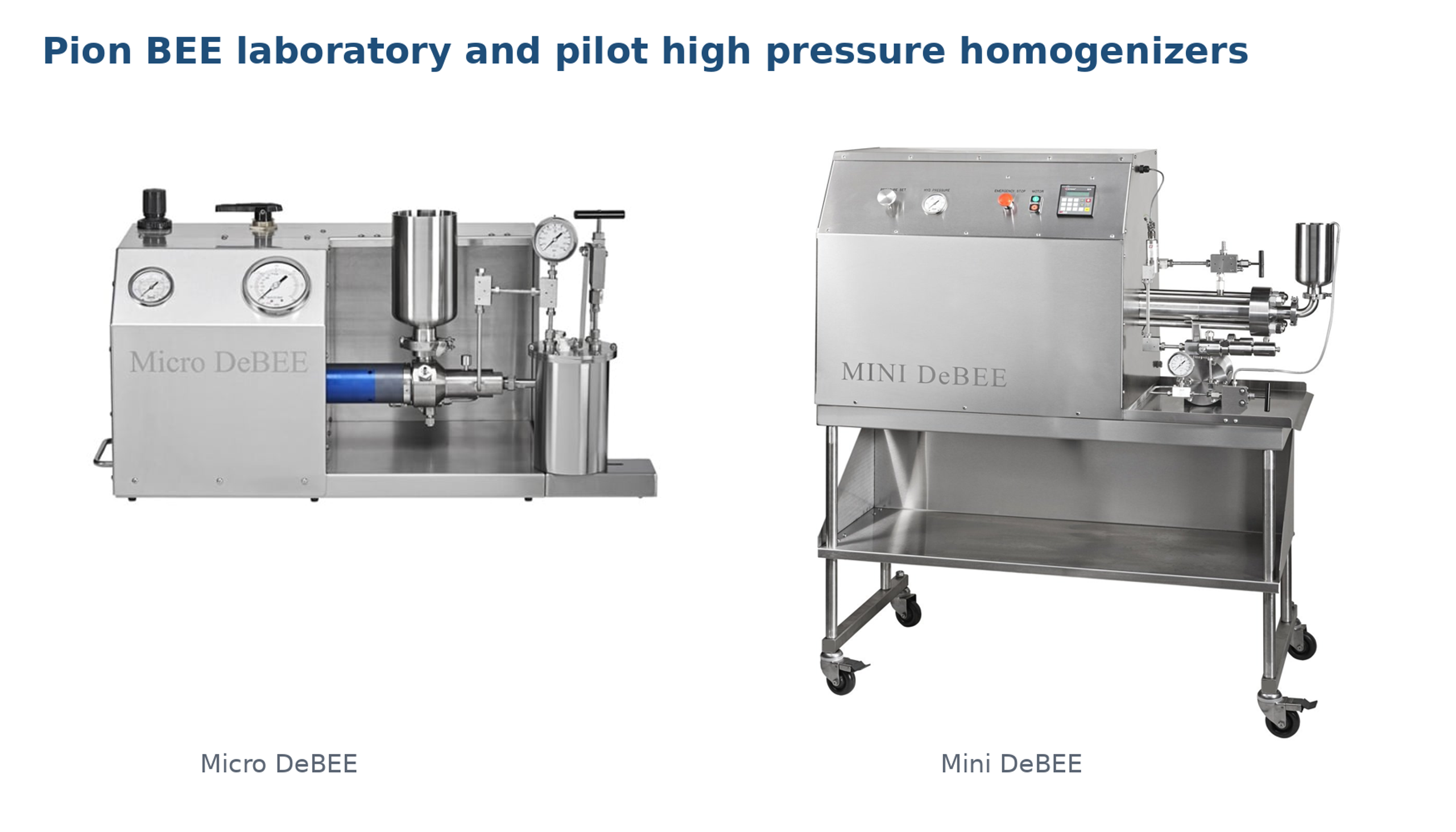
Figure 43. Pion BEE Micro DeBEE and Mini DeBEE equipment [50, 51].
4.7.2 Emulsifying Cell and Controllable Force Balance
The DeBEE architecture uses an intensifier pump to force product through a replaceable nozzle into an Emulsifying Cell. The nozzle creates sudden acceleration and pressure decrease. Cavities form in and immediately downstream of the jet when the local static pressure approaches the liquid vapor pressure or activates gas nuclei. An absorption cell, reactor surface, or controlled flow reversal then converts jet momentum into turbulence, shear, impact, and pressure recovery. Public patent descriptions and current product support material identify cavitation as an intentional mechanism rather than merely an incidental effect [50, 53-55].
Pion distinguishes two principal flow configurations. In parallel flow, product travels through the nozzle and downstream passages without immediate wall impact. Current support literature describes this configuration as providing maximum cavitation with relatively laminar approach flow and identifies cell lysis as a typical use. In reverse flow, the jet impacts a reactor surface and reverses direction, increasing impact and shear. This configuration is commonly selected for difficult particles and emulsions. The modular cell allows nozzle size, backpressure, cooling, and flow pattern to be varied independently [50, 51].
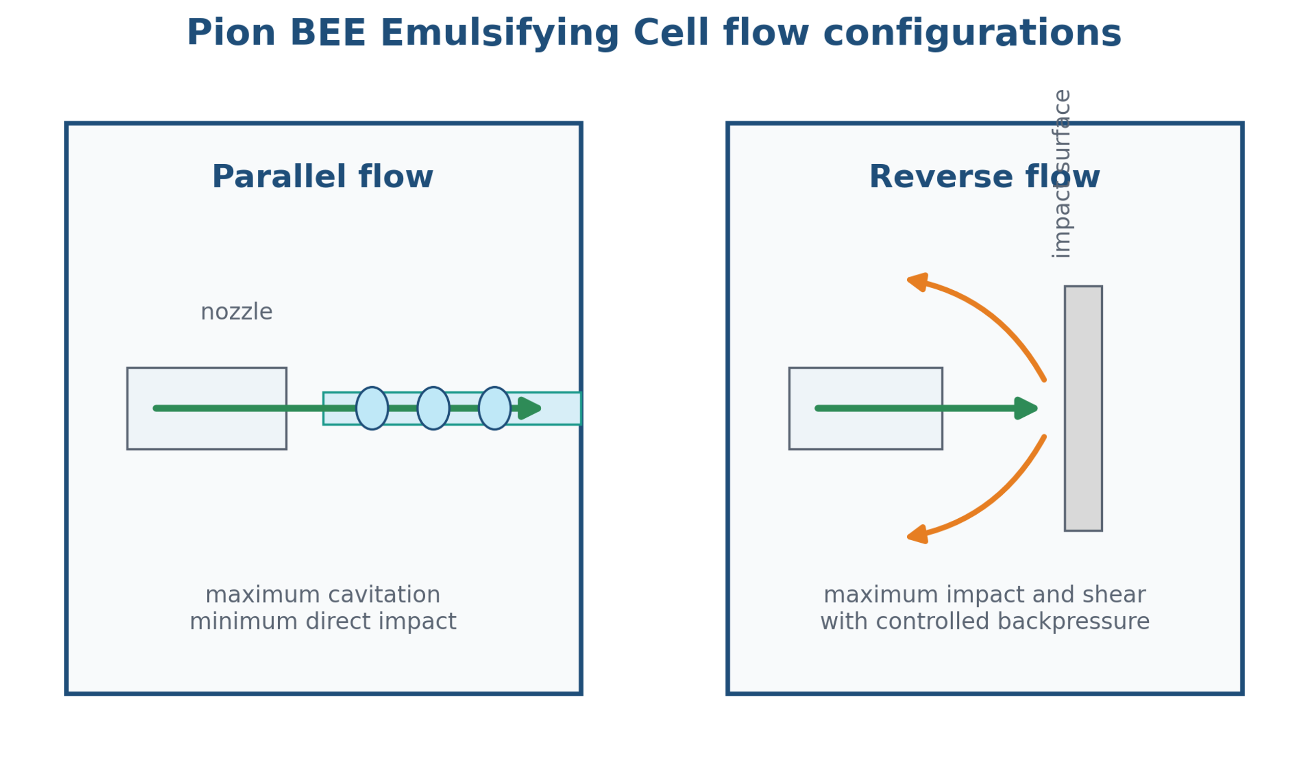
Figure 44. Parallel and reverse Pion BEE Emulsifying Cell flow configurations [50, 51, 53-55].
4.7.3 Hydraulic Analysis and Backpressure
For a nozzle of total area An, a practical incompressible flow estimate is:
where p₁ is pressure upstream of the nozzle and p₂ is the effective pressure in the receiving cell. The downstream backpressure ratio may be defined as:
where is controlled pressure downstream of the primary interaction region. The corresponding jet cavitation number is:
The mean time available for cavity growth between the nozzle and the principal impact or recovery location is estimated by:
These equations separate four controls that are often collapsed into one pressure setting: nozzle area, pressure difference, downstream backpressure, and distance to pressure recovery. Reducing backpressure can increase cavity volume but can also delay collapse or promote choking. Increasing backpressure can intensify collapse near the cell but can also suppress inception. The useful operating window is therefore application specific. A study using a high pressure homogenizer with selectable flow pattern and backpressure control found that pressure, number of passes, flow pattern, and backpressure all influenced nanoemulsion droplet size and distribution [57].
4.7.4 Equipment Range
Table 13. Selected current and legacy Pion BEE equipment ratings. Values depend on product, nozzle, and operating configuration.
| Processor | Role | Minimum sample | Pressure | Vendor reported flow |
|---|---|---|---|---|
| Nano DeBEE | Benchtop development | About 12 mL | Up to 45,000 psi | Application and setup dependent [50] |
| Micro DeBEE | Compact laboratory unit | About 15 mL | Up to 45,000 psi | Up to about 15 L/h [52] |
| Mini DeBEE | Pilot and small production | About 20 mL | Up to 45,000 psi | About 20 L/h at 30,000 psi; about 15 L/h at 45,000 psi [51] |
| DeBEE 2000 | Pilot and production | Process dependent | Up to 45,000 psi | Vendor literature reports up to about 2 L/min [52] |
| DeBEE 4000 | Production and automated systems | Process dependent | Configuration dependent | Custom plant capacity [55] |
Pion states that the Nano DeBEE results scale to larger Mini DeBEE and DeBEE 2000 systems because they use the same underlying EC technology. This is a valuable starting point but not a substitute for engineering verification. At larger scale, the intensifier stroke, check valve dynamics, cooling duty, pressure pulsation, product hold up, and number of parallel high pressure paths can change even when the nozzle and EC geometry are retained [50, 51].
4.7.5 Process Control, Safety, and Product Qualification
A defensible operating record should include primary pressure, backpressure, nozzle designation and measured condition, EC arrangement, parallel or reverse flow mode, flow rate, number of passes, inlet and outlet temperature, cooling duty, product viscosity, gas condition, and sample recovery. The user should record whether the reported pressure is pump pressure or pressure immediately upstream of the nozzle. For small samples, line and cell hold up can materially bias yield and concentration.
High pressure cavitation homogenizers require positive mechanical safeguards: pressure rated tubing and fittings, guarded intensifier components, relief and depressurization procedures, interlocks for cooling and feed, documented maintenance intervals, and inspection for erosion. Sanitary and pharmaceutical service additionally requires drainability, material certificates, cleaning validation, sterilization or sanitization strategy, and control of wear particles. The fact that cavitation is generated intentionally does not eliminate erosion risk; it moves the design objective toward controlled collapse in a replaceable or fluid core region.
4.7.6 Comparative Selection
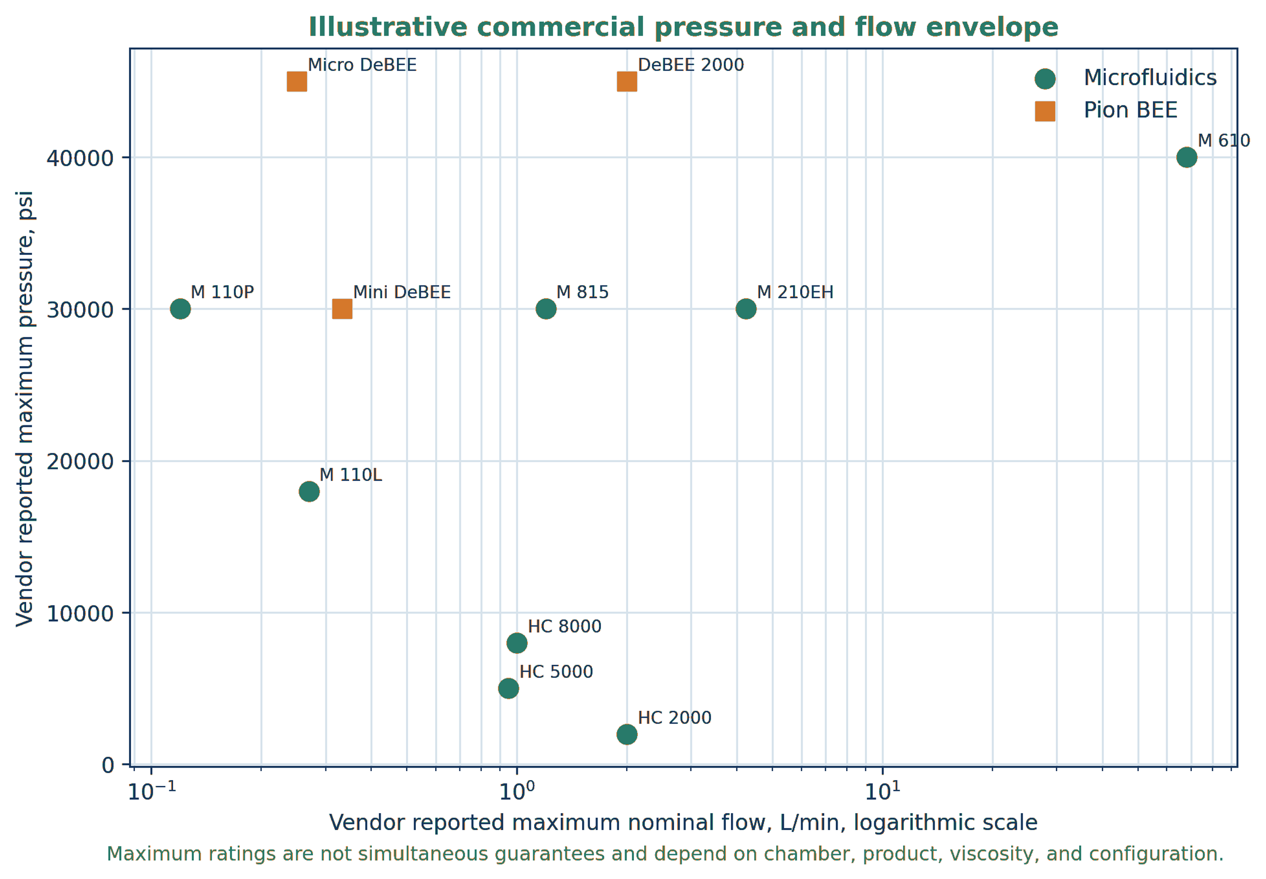
Figure 45. Illustrative pressure and flow envelope assembled from Microfluidics and Pion BEE information [38, 39, 42, 44, 50-52].
Table 14. Engineering comparison of Microfluidics and Pion BEE high pressure interaction systems with conventional static cavitation equipment.
| Architecture | Dominant controllable features | Principal strengths | Primary risks and verification |
|---|---|---|---|
| Microfluidics Y type interaction chamber | Constant pressure, opposed microjets, fixed slots, optional parallel slots | Uniform treatment, strong impingement, narrow geometry, scale continuity | Small passage blockage, chamber wear, heat generation, gas sensitivity; verify actual cavitation contribution. |
| Microfluidics Z type and APM | Tortuous single stream, direction changes, staged passage sizes | Pre dispersion, deagglomeration, cell disruption, protection of smaller downstream chamber | Pressure loss distribution and wear can change with chamber sequence. |
| Pion BEE parallel flow EC | Nozzle size, primary pressure, backpressure, straight flow path | High cavitation contribution, low hold up, modular process development | Collapse location, choking, and gas cushioning require mapping. |
| Pion BEE reverse flow EC | Nozzle, impact surface, flow reversal, backpressure | Maximum direct impact and shear for difficult dispersions and emulsions | Localized erosion, heating, product sensitivity, and impact surface condition. |
| Conventional static cavitator | Orifice, Venturi, vortex, or baffle geometry with pump supplied pressure drop | Simple flow through installation, large passages possible, no moving interaction element | Broader exposure distribution, pressure loss, erosion, and less direct control of impact geometry. |
Microfluidics and Pion BEE systems are best treated as controllable high pressure interaction platforms in which cavitation, shear, impact, and turbulence contribute in different proportions. The selection should follow the product objective. Cell rupture may benefit from strong cavitation and rapid decompression. Hard agglomerates may require high impact and repeated passes. Emulsions require both droplet breakup and sufficiently rapid surfactant adsorption. Sensitive biologics require strict cooling and a pass limit. In every case, the useful metric is product quality at a declared electrical energy, temperature history, and wear state, not the name of the mechanism alone.
4.8 Commercial Specification
A commercial request for quotation should define the fluid envelope, not a single design point. Required data include minimum and maximum density, viscosity, vapor pressure, temperature, solids loading, particle size, gas fraction, corrosivity, and cleanability. The vendor should provide guaranteed flow, inlet and outlet pressure, differential pressure, shaft or electrical power, temperature rise, material of construction, pressure rating, nozzle loads, vibration limit, noise level, seal or gasket life, and expected inspection interval. For dynamic equipment, the guarantee should also include speed range, overspeed protection, rotor balance standard, and bearing life. For static equipment, it should include minimum passage, removable element details, and a pressure drop curve.