
Technical publication
Back to publications
Reactors & equipment
Hydrodynamic Cavitation Technological Equipment
okozyuk.com
Published
Read complete publication for whole-document Find and printing. Browser Find and native printing on this reader include only loaded content.
3. Dynamic Hydrodynamic Equipment
Dynamic hydrodynamic cavitation equipment uses a moving rotor, disk, blade, pin, tooth, dimple, cavity, or oscillating element to create time dependent low pressure zones. A rotor may also generate the system flow, or a separate pump may supply the machine. The dynamic device can therefore combine cavitation, high shear, pumping, mixing, and heat generation. It is controlled by rotational speed, rotor diameter, clearances, flow rate, inlet pressure, backpressure, and residence time. Unlike a static restriction, it also has mechanical limits associated with stress, critical speed, balance, seal velocity, bearing load, and vibration [2, 3].
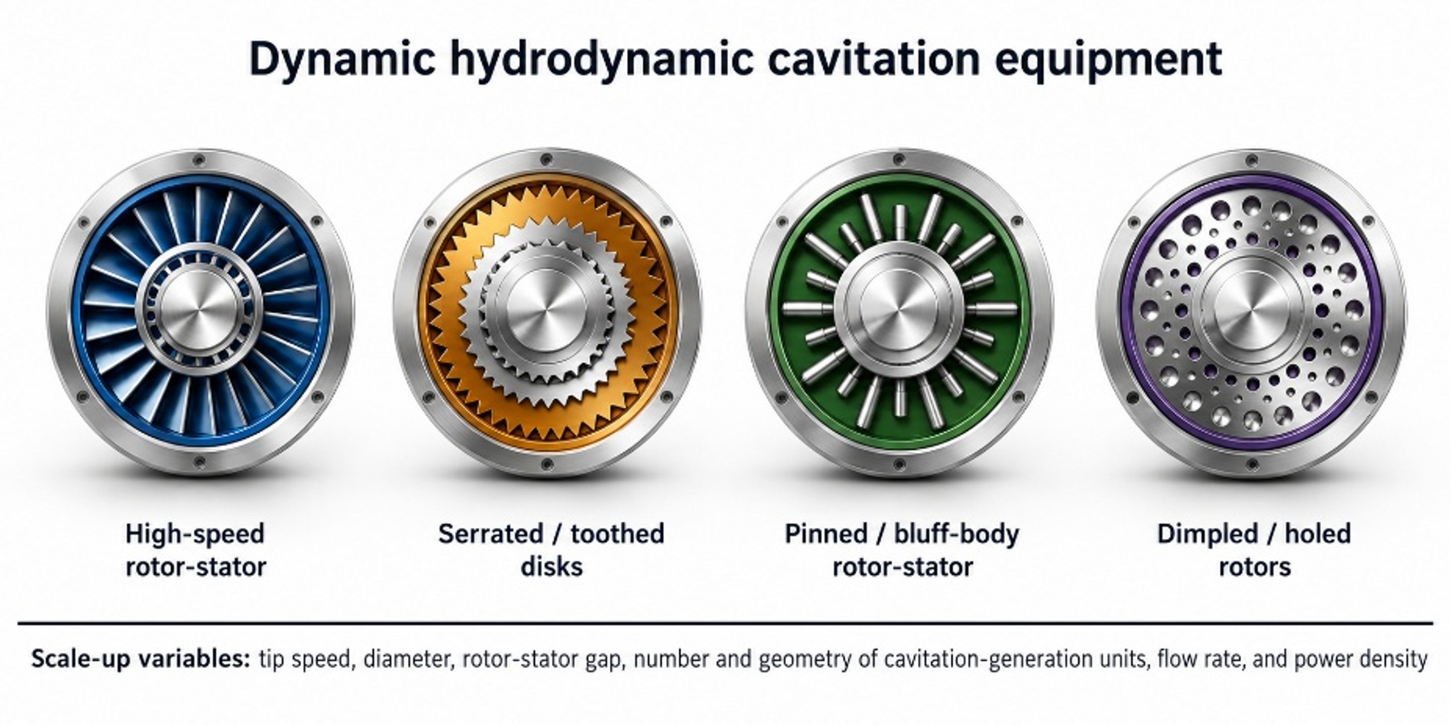
Figure 16. Major families of dynamic hydrodynamic cavitation equipment [58].
Rotor tip speed is a primary dynamic similarity variable:
where ω is angular velocity, R is rotor radius, D is rotor diameter, and n is rotational frequency in revolutions per second. Tip speed determines the magnitude of local relative velocity, but does not define the complete flow because throughflow, gap velocity, blade count, and stator interaction also contribute. A rotational Reynolds number may be written as:
The characteristic length and speed used in must be stated. For a narrow rotor stator gap, a gap based Reynolds number may be more informative than a rotor radius definition. Dynamic scale up based only on equal tip speed can preserve one stress scale while changing passage frequency, residence time, torque, power density, and cavity recovery time.
A rotating cavitator should be characterized by the relative velocity and repetition frequency at each cavitation generating element, not by shaft speed alone. For Ne identical pins, teeth, grooves, holes, or recesses encountered once per revolution, the nominal passage frequency is:
where n is rotational frequency in revolutions per second. In a narrow rotor stator clearance δ, the first estimate of the gap shear rate is:
The shaft power supplied to the liquid and mechanical losses is determined from measured torque T:
A dimensionless power coefficient permits comparison of geometrically related rotors:
If a fluid element remains in the active region for a mean residence time tres, the nominal number of cyclic encounters is:
Equations (16) through (20) are equipment descriptors, not direct measures of collapse intensity. The actual pressure amplitude also depends on inlet pressure, vapor loading, local slip, gap flow, throughflow, stator interaction, and gas content. Nevertheless, they expose why equal tip speed can produce unequal treatment: a larger rotor changes encounter frequency, residence time, torque, and power density even when utip is preserved.
Dynamic cavity rotors use circumferential recesses, dimples, pins, or holes to create many local low pressure events during every revolution. A liquid element may experience repeated acceleration, wake formation, cavity growth, and pressure recovery before leaving the active chamber. The process response therefore depends on feature count, rotational speed, residence time, local gas content, and the pressure field surrounding the rotor. Figure 17 shows the mechanism without assigning it to a single proprietary geometry [3, 16, 31].
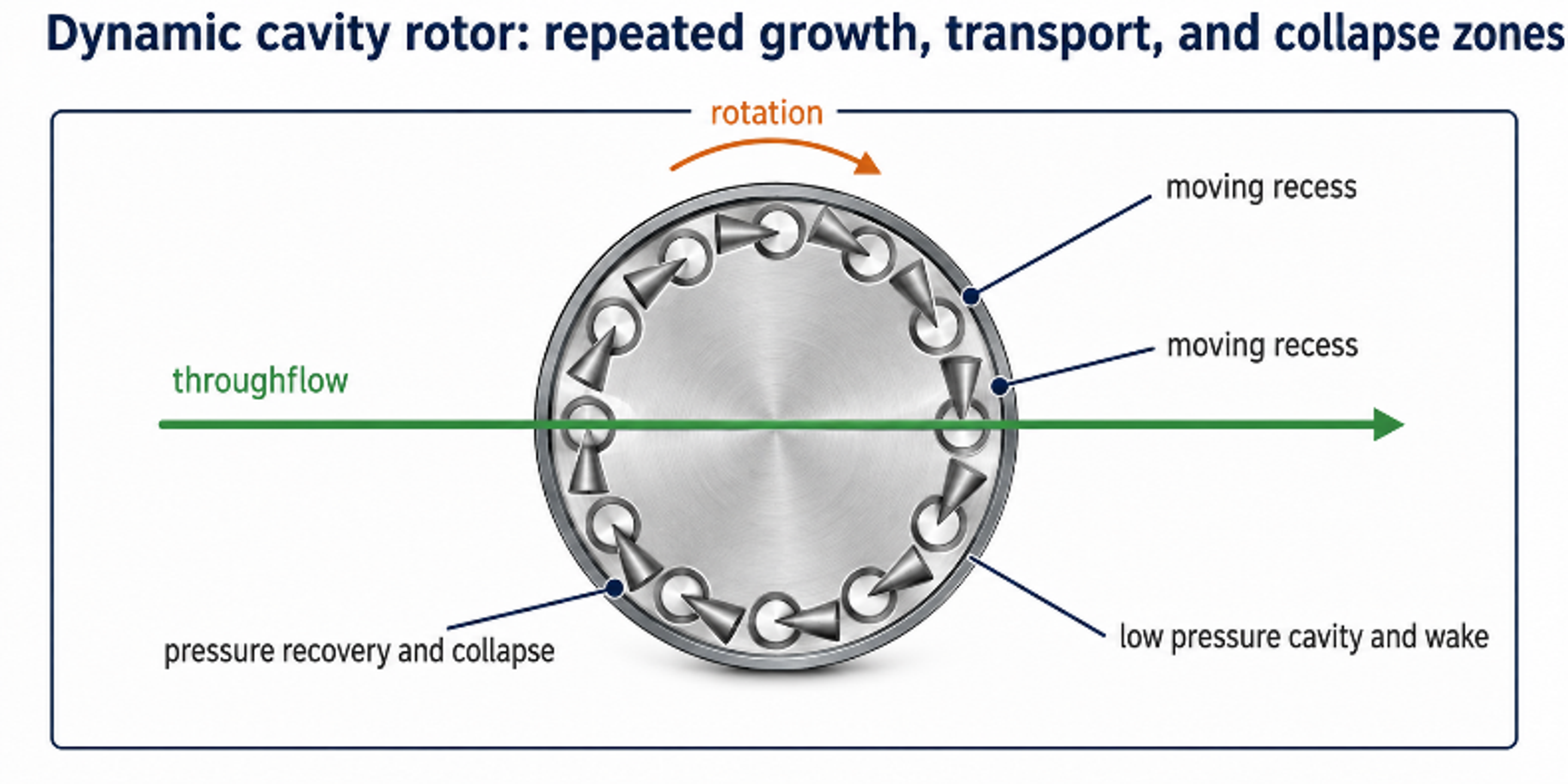
Figure 17. Dynamic cavity rotor showing repeated cavity growth, transport, pressure recovery, and collapse zones [58].
3.1 Dynamic Device Families and Operating Mechanisms
High speed homogenizers use blades or rotor stator slots to create separated jets, rapid shear, and pressure fluctuations. Serrated disc devices create periodic Venturi like passages as rotor and stator teeth pass each other. Dimpled or indentation rotors generate recirculation and low pressure inside cavities on the moving surface. Pinned disc devices create wakes behind cylindrical pins and pulsating gap flow as rotor and stator pins pass. Holed or cavity rotors create low pressure inside dead ended recesses, with collapse occurring as liquid leaves the cavity or enters a higher pressure region. Hybrid designs deliberately combine two or more of these mechanisms [2, 3].
Table 7. Dynamic hydrodynamic cavitation equipment.
| Dynamic family | Cavitation generation unit | Dominant variables | Engineering characteristics |
|---|---|---|---|
| High speed rotor stator | Slots, blades, teeth, or radial jets | Speed, slot width, gap, blade count, throughflow | Strong mixing and shear; compact; close clearances; seal and wear control required. |
| Serrated disc | Periodic narrowing between rotor and stator teeth | Tooth angle, axial gap, speed, inlet pressure | Venturi like cyclic passages; gap is highly influential and difficult to preserve at large scale. |
| Dimpled or indentation rotor | Recess recirculation and pressure depression | Dimple size, depth, inclination, pitch, rotor speed | Large number of local cavities; surface erosion must be inspected. |
| Pinned disc | Cylinder wakes and pulsating rotor stator passages | Pin diameter, pitch, pin count, speed, flow and inlet pressure | Robust replaceable pins; intense cavitation at high flow; good pilot scale evidence. |
| Holed or cavity rotor | Dead ended cavities or rows of holes in a moving rotor | Hole diameter, depth, rows, clearance, speed | Cavitation localized inside recesses; can combine heating and mixing; sanitary designs available. |
| Axial or radial hybrid | Combination of blade wakes, cavities, and restrictions | Axial flow coefficient, rotor geometry, staging | Flexible high throughput architecture but more complex hydraulic characterization. |
3.2 Pinned Disc Rotor Stator Cavitators
Pinned disc equipment illustrates how rotating bluff bodies can combine wake cavitation with high rate interfacial renewal. A practical design uses one or more rotating discs carrying pins that pass stationary pins or baffles. Exact dimensions are product and vendor specific; the generic cross section in Figure 18 emphasizes the repeating acceleration and recovery sequence rather than a particular published prototype.
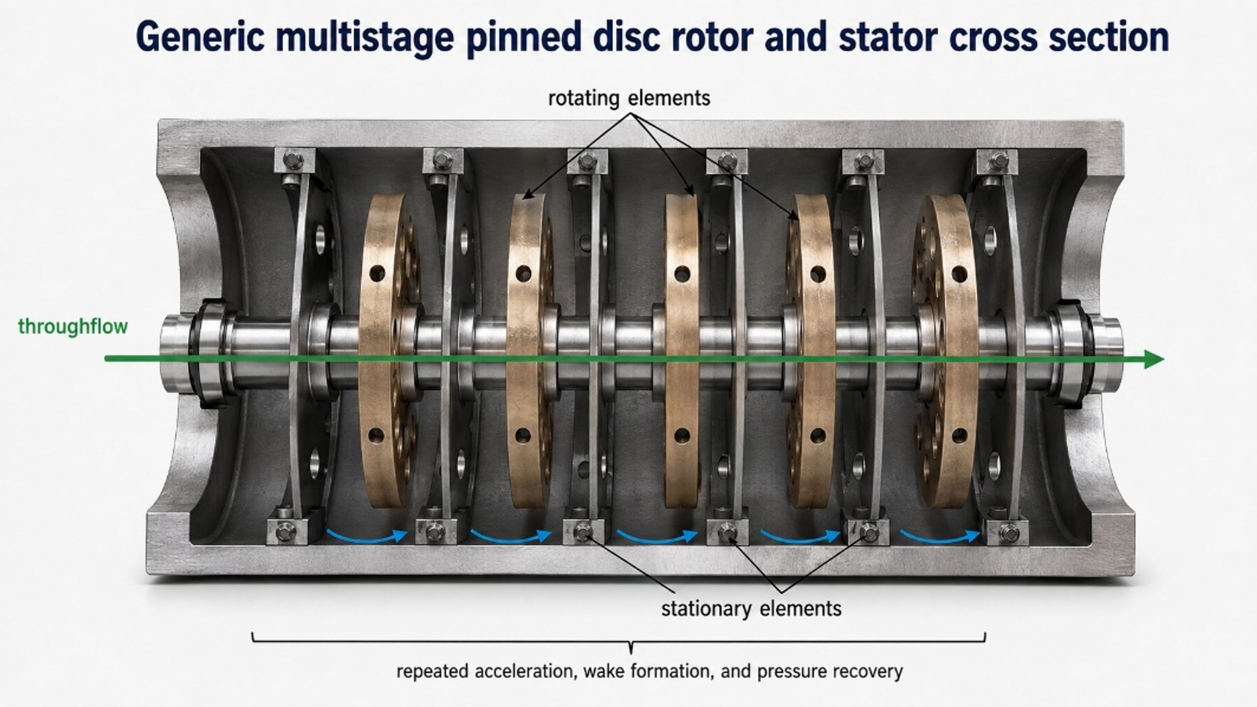
Figure 18. Generic multistage pinned disc rotor and stator cross section [58].
The working mechanism differs from a serrated disc because the principal low pressure structures arise behind cylindrical or shaped bluff bodies and in the transient passages between moving and stationary elements. The pin diameter, pitch, radial position, axial clearance, blockage ratio, and throughflow determine wake interaction and vapor residence time. Equal rotational speed does not imply equal treatment when the pin count, active volume, or flow changes [3, 16].
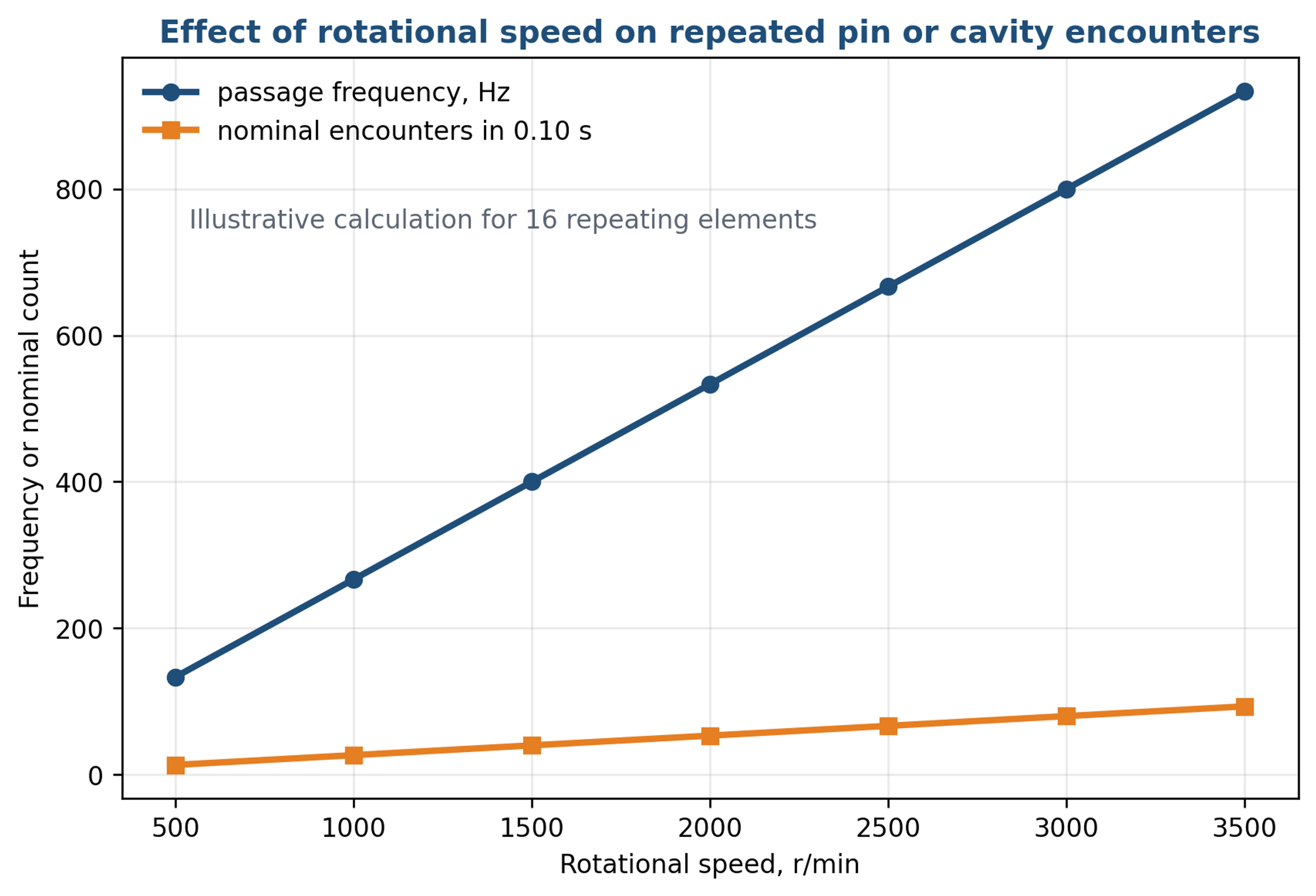
Figure 19. Passage frequency and nominal encounter count versus rotational speed for sixteen repeating rotor features. Calculation using Equations (16) and (20) [58].
Figure 20 provides a plan view of a general pinned arrangement. The rotor pins and stator pins should be located so that the liquid has a continuous discharge path and so that no blind pocket retains solids during shutdown. Replaceable pins can simplify wear management, but their fasteners and roots must be checked for fatigue, fretting, and imbalance.
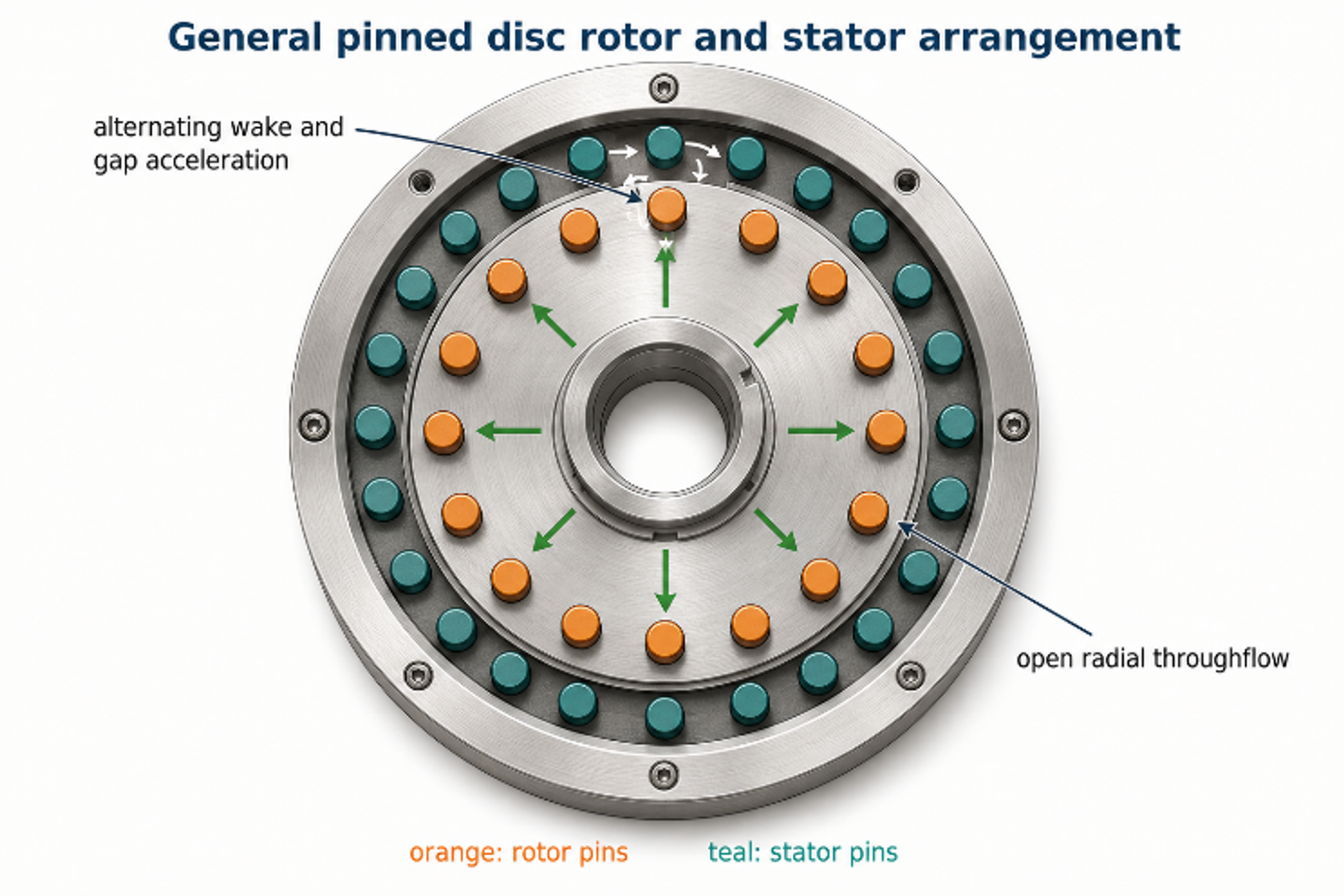
Figure 20. General pinned disc rotor and stator arrangement showing open radial throughflow and repeated wake generation [58].
Performance of a pinned disc machine must be demonstrated with a complete operating map. Required measurements include flow, inlet and outlet pressure, rotational speed, shaft torque, electrical power, temperature rise, gas content, particle or droplet distributions, and inspection after the test. Reported treatment benefit must be separated from simple recirculation, pumping, and thermal effects.
3.3 Cavity Rotor and Controlled Cavitation Machines
Cavity rotor machines use rows of holes or recesses around a cylindrical rotor. Rotation draws liquid into the recesses and creates low pressure near the cavity bottoms; pressure rises as the cavity rotates into a different region or discharges into the housing. Commercial versions may be configured for simultaneous heating and mixing. Locating the cavity in a recess away from the housing wall is intended to reduce destructive collapse on external surfaces, but the rotor, cavity edges, and close clearance regions remain subject to cyclic loading and require inspection [10, 16, 19, 20].
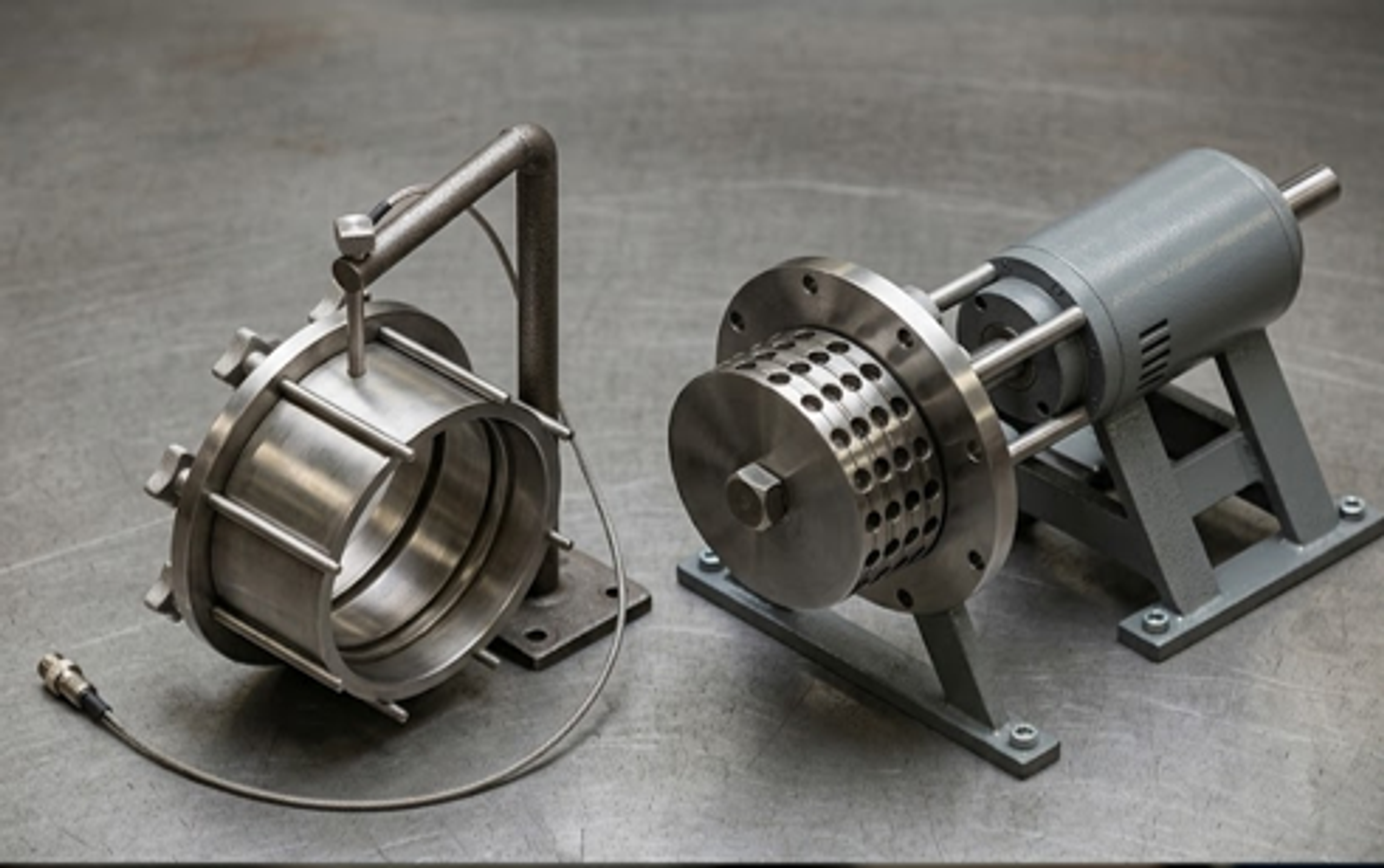
Figure 21. Dynamic controlled cavitation device with a holed rotor and swing open housing for cleaning [16].
For food, pharmaceutical, and other sanitary duties, disassembly and cleanability may determine the practical value of a dynamic cavitator. The patent drawing in Figure 21 uses a swing open housing to expose the rotor. Industrial specifications should define clean in place and steam in place conditions, product contact materials, seal arrangement, drainability, elastomer certification, maximum allowable working pressure, and procedures for verifying the absence of residual product. The cavitation performance of a machine that is difficult to clean is irrelevant when contamination control prevents its use [16, 19, 23].
3.4 Rotating Groove, Bore Hole, and Disk Reactor Concepts
A radial groove rotor directs liquid through repeated converging and expanding passages. The groove entrance accelerates the liquid, while the exit and surrounding stator create pressure recovery, wake interaction, and possible cavity collapse. Groove depth, curvature, radial angle, outlet area, clearance, and rotor speed must be reported. Figure 22 is an original schematic and is not tied to restricted publication. Closely related open concepts are disclosed in public rotor and stator patents [30, 31].
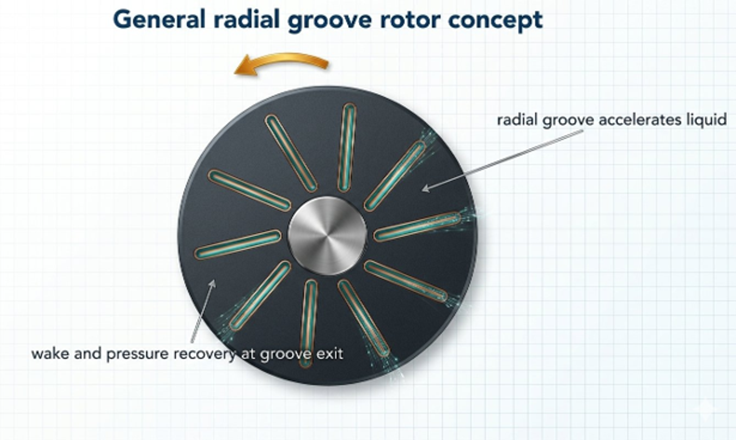
Figure 22. General radial groove rotor concept showing acceleration within grooves and pressure recovery at the exits [58].
A concentric bore hole rotor stator places rows of blind holes on opposing cylindrical surfaces. As the rotor moves, holes pass between aligned and blocked positions, creating repeated compression and decompression of the trapped liquid. US Patent 10,315,172 describes rotor and stator hole diameter, depth, pitch, and clearance as the principal design variables. In practice, the closed ends and hole roots require careful fatigue and cleaning assessment, while the minimum clearance controls both leakage flow and mechanical tolerance [31].
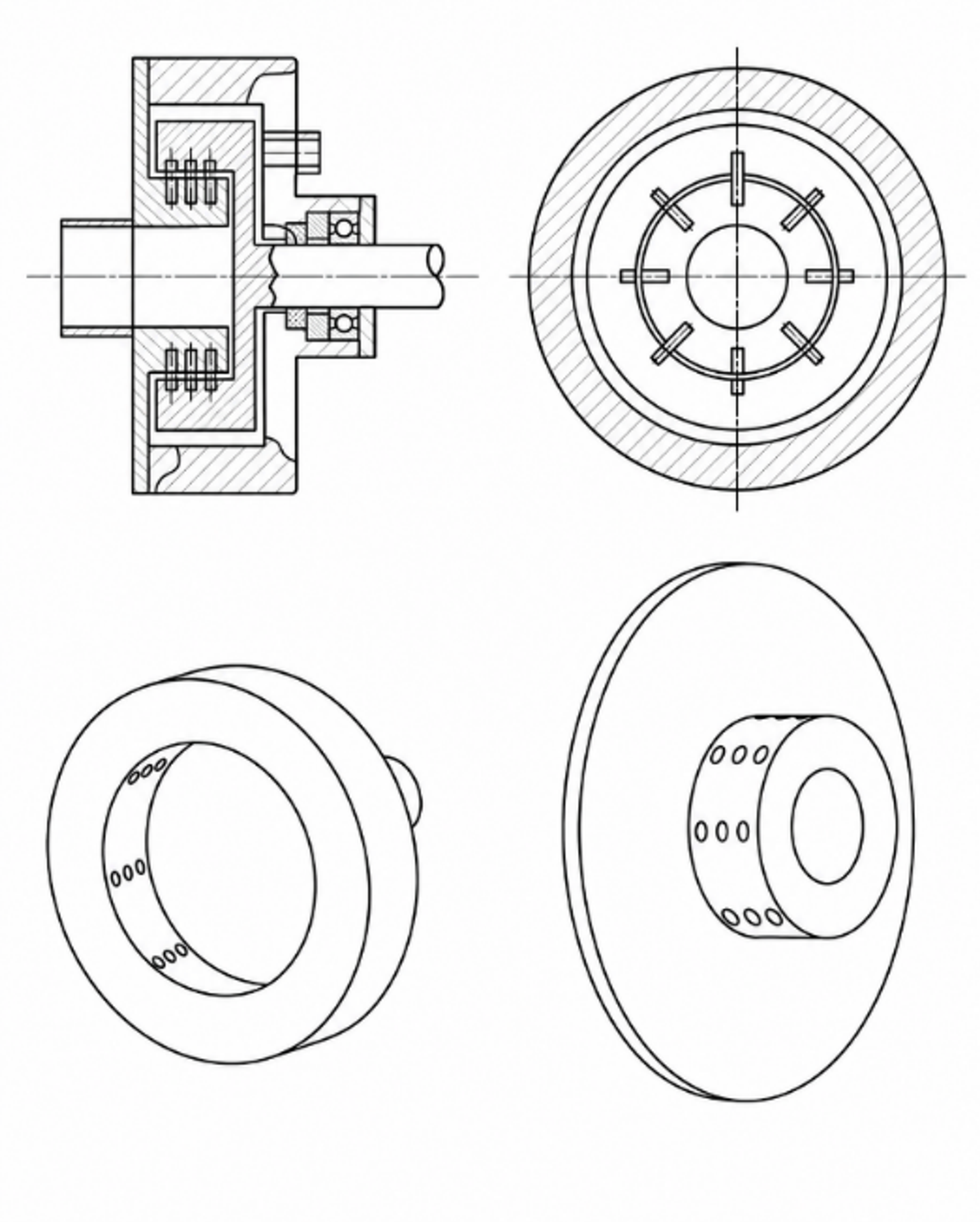
Figure 23. Concentric rotor and stator with circumferential rows of blind bore holes [31].
Rotating disk patents also disclose tank mounted and inline arrangements in which liquid enters through holes in a disk and passes radial cavitation assemblies located near the disk perimeter. Multiple disks can be stacked on one shaft to increase the number of active zones. Such systems provide flexibility in body shape, nozzle count, and staging, but they impose large cyclic loads on the disk rim and can create strong vessel circulation that complicates residence time analysis [30].
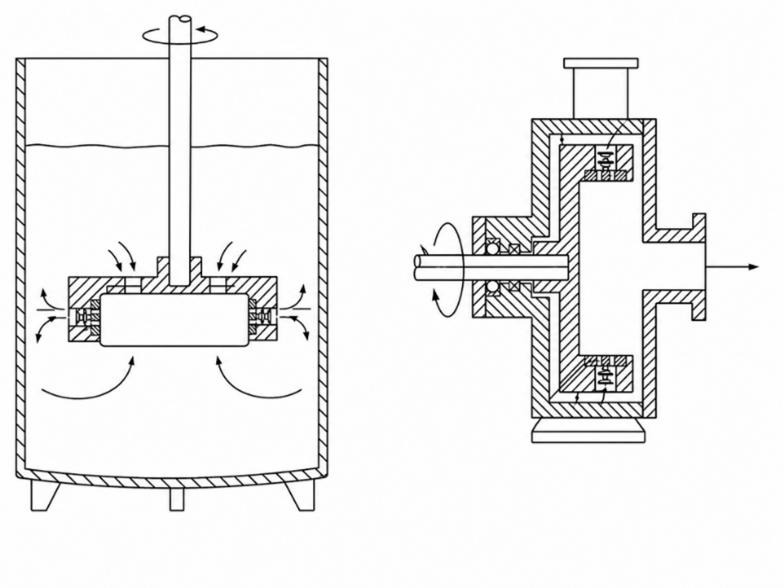
Figure 24. Tank mounted and inline rotating cavitational mixing and pumping arrangements [30].
The historical Soviet reactor SU 1099990 combined an inlet flow interrupter with rotating and stationary perforated disks ahead of a pump like impeller. Unequal circumferential positioning of adjacent windows was intended to create pulsating velocity and pressure fields while the impeller supplied preliminary mixing and throughflow. The design illustrates an early hybrid strategy in which a conventional pumping element and a rotating cavitation element share one housing [33].
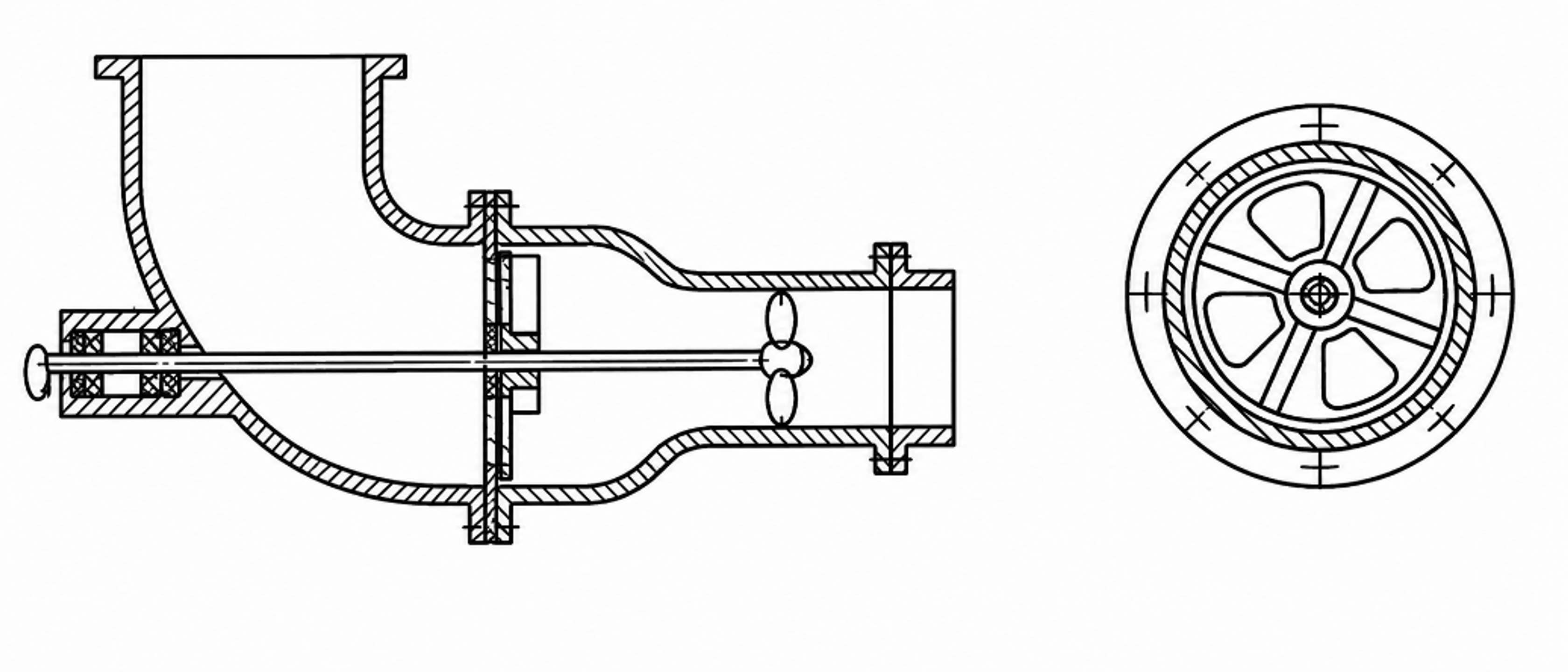
Figure 25. Longitudinal and transverse views of a Soviet rotating cavitation reactor with perforated rotating and stationary disks [33].
Table 8. Additional dynamic cavitation architectures.
| Architecture | Cavitation generating geometry | Primary controls | Dominant engineering risks |
|---|---|---|---|
| Circumferential rotating drum [2] | Repeated recesses or slots on a cylindrical rotor facing a stator | Rotor speed, feature depth and pitch, radial clearance, throughflow | Rotor balance, fatigue at recess roots, wall erosion, seal and bearing load |
| Pinned disc [3] | Cylinder wakes and periodic rotor stator pin passage | Pin diameter, count, pitch circles, speed, suction pressure | Pin fatigue, vibration, synchronous loading, solids lodging between pins |
| Rotor radial groove [3] | Curved or radial rotor grooves interacting with stator slots | Groove angle and depth, stator slot pattern, speed, flow coefficient | Hydraulic machine coupling, rotor erosion, nonuniform flow, casing vibration |
| Concentric bore hole rotor stator [31] | Blind holes cyclically aligned and blocked on opposing cylindrical surfaces | Hole diameter and depth, pitch, clearance, relative speed | Trapped product, cleaning validation, hole root fatigue, tight tolerance |
| Rotating disk with peripheral cavitation assemblies [30,33] | Disk holes, nozzles, or perforated rotor stator windows | Disk diameter, stage count, nozzle resistance, vessel circulation | Rim stress, shaft bending, broad residence time distribution, vessel loads |
Dynamic device selection should therefore be based on a combined hydraulic and mechanical map. The map should include flow, inlet and outlet pressure, speed, torque or true electrical power, temperature, product quality, mechanical loading, and post run condition. A design that generates a dense visible vapor field but loses pumping capacity, enters unstable slip, or exceeds a vibration limit is not a useful industrial operating point.
3.5 Mechanical Design and Control
Dynamic machines should be treated as rotating equipment, not merely as reactors. The rotor must be checked for centrifugal stress, fatigue at recess roots, overspeed, critical speed, and balance in both dry and wetted conditions. The drive train requires a service factor for transient torque and loaded operation. Seal selection must account for product lubricity, temperature, solids, gas fraction, and pressure reversal. Bearing isolation and a leakage collection strategy are essential where product purity is critical.
The control system should interlock motor speed with confirmed liquid flow, tank level, seal flush, and permissive inlet pressure. Starting a cavity rotor without adequate liquid can overheat seals or expose the rotor to uncontrolled vibration.