
Technical publication
Back to publications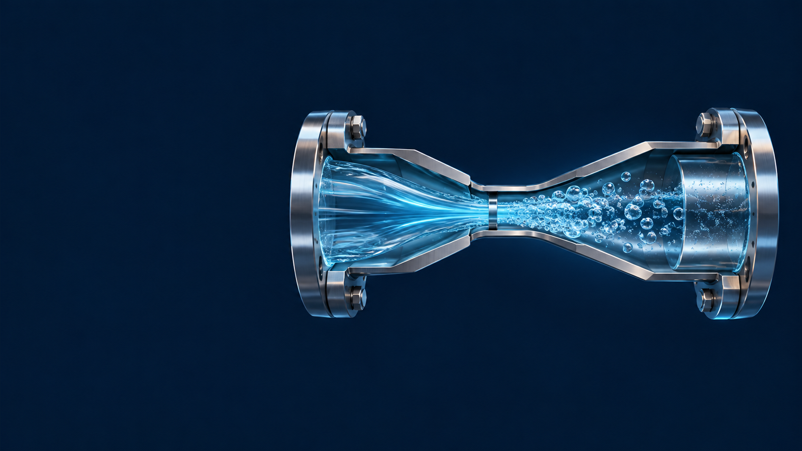
Reactors & equipment
Hydrodynamic Cavitation Technological Equipment
okozyuk.com
Published
Read complete publication for whole-document Find and printing. Browser Find and native printing on this reader include only loaded content.
2. Static Hydrodynamic Cavitation Equipment
Static hydrodynamic cavitation devices convert the pressure energy generated by a pump into local acceleration followed by a pressure recovery zone. They are often manufactured as replaceable cartridges, plates, spools, or blocks, allowing for rapid testing during the development process. Their reproducibility depends on geometric details. Nominal parameters such as nozzle diameter or the throat diameter of a Venturi tube, are insufficient unless accompanied by specifications for plate thickness, edge condition, open area ratio, throat length, diffuser angle, chamber diameter, and reference pressure locations [2, 4-6].
2.1 Orifice Based Devices
An orifice device accelerates liquid through one or more openings in a plate, insert, nozzle, or multi aperture cartridge. A sharp edged plate produces a vena contracta downstream of the physical opening. The static pressure is lowest near this contracted jet, where vapor cavities form if the pressure falls below the effective inception threshold. Cavities are convected into a pressure recovery region and collapse as the jet expands and mixes with surrounding liquid. Multi hole plates distribute the total flow among smaller jets and can increase the number of active cavitation zones, whereas a single large opening is less prone to blockage and easier to characterize [2, 4-6].
For an incompressible liquid, a practical orifice flow relation is:
where is the discharge coefficient, is the total open area, Δp is the pressure difference between the selected upstream and downstream stations, and ρ is the liquid density. The discharge coefficient is not universal; it varies with Reynolds number, thickness to diameter ratio, edge geometry, multihole interaction, and downstream geometry. The diameter ratio and total open area fraction are:
where do is opening diameter for a circular hole, D is pipe diameter, Nh is number of holes, and Ap is pipe cross sectional area. For noncircular openings, hydraulic diameter and actual open area should replace a nominal diameter. The total open area determines bulk velocity, but hole pitch, radial position, and the ratio of jet spacing to downstream chamber diameter determine jet interaction and cloud coalescence.
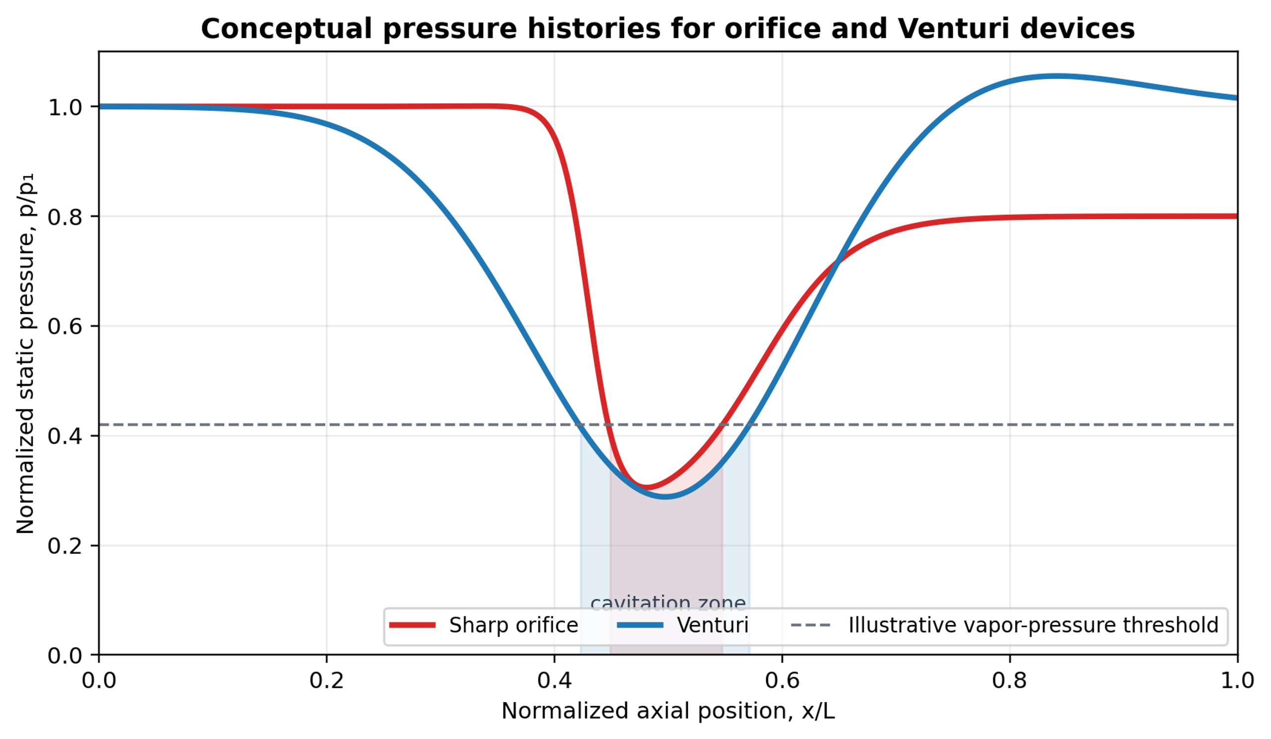
Figure 2. Conceptual pressure histories for orifice and Venturi devices operated at comparable minimum pressure. The orifice exhibits a more abrupt pressure drop and recovery, while a Venturi distributes the recovery over the diffuser [58].
Table 3. Orifice design variables and their engineering significance.
| Variable | Effect on cavitation and equipment performance | Recommended reporting practice |
|---|---|---|
| Opening diameter and total area | Controls velocity, pressure drop, nuclei activation, solids passage, and pumping requirement. | Report each opening dimension, number of openings, open area fraction, and tolerance. |
| Plate thickness and L/do | Changes internal shear, jet attachment, vena contracta location, and permanent loss. | Report actual thickness and whether the opening is cylindrical, tapered, or counterbored. |
| Inlet edge | A sharp edge promotes separation; a radius or chamfer shifts inception and alters Cd. | Specify edge radius or chamfer angle and inspection method. |
| Hole pattern and pitch | Determines jet interaction, cloud overlap, and local loading of the downstream wall. | Provide drawing or coordinates, not only number of holes. |
| Downstream chamber | Controls pressure recovery, collapse location, recirculation, and erosion. | Report chamber diameter, length, outlet geometry, and pressure reference positions. |
| Backpressure | Moves the collapse zone upstream or downstream and can suppress or choke cavitation. | Measure and control independently from inlet pressure. |
| Gas and solids | Gas cushions collapse; solids supply nuclei but may block small holes and accelerate erosion. | Report degassing, gas injection, solids fraction, size distribution, and filtration. |
A thin sharp edged plate is easy to replace but may localize collapse near the downstream plate face or pipe wall. A thicker plate behaves increasingly like a short nozzle. Tapered and stepped openings can separate cavity generation from collapse. Slit orifices create sheet like jets and may be less sensitive to individual particle blockage, but the local stress field differs from that of circular jets. Direct comparison of devices requires matching the full pressure drop versus flow rate characteristic rather than matching nominal hole diameter alone. Experiments comparing orifice, Venturi, swirl assisted, and vortex devices found similar per pass pollutant degradation when the devices were designed to have comparable hydraulic characteristics, while swirl moved cavities away from solid surfaces [4, 5].
2.1.1 Multistage and Adjustable Orifice Systems
Multiple restrictions may be installed in series to create repeated pressure drop and recovery zones in one body. The interstage spacing must be long enough to establish the intended recovery and short enough to avoid unnecessary hold up. Adjustable baffles permit the number and strength of active stages to be changed without replacing complete housing. This flexibility is useful in pilot plants that process liquids with varying viscosity or solids content, but cumulative pressure loss, stagnant pockets, cleaning access, and reproducibility of the adjustment position must be addressed [13, 14].
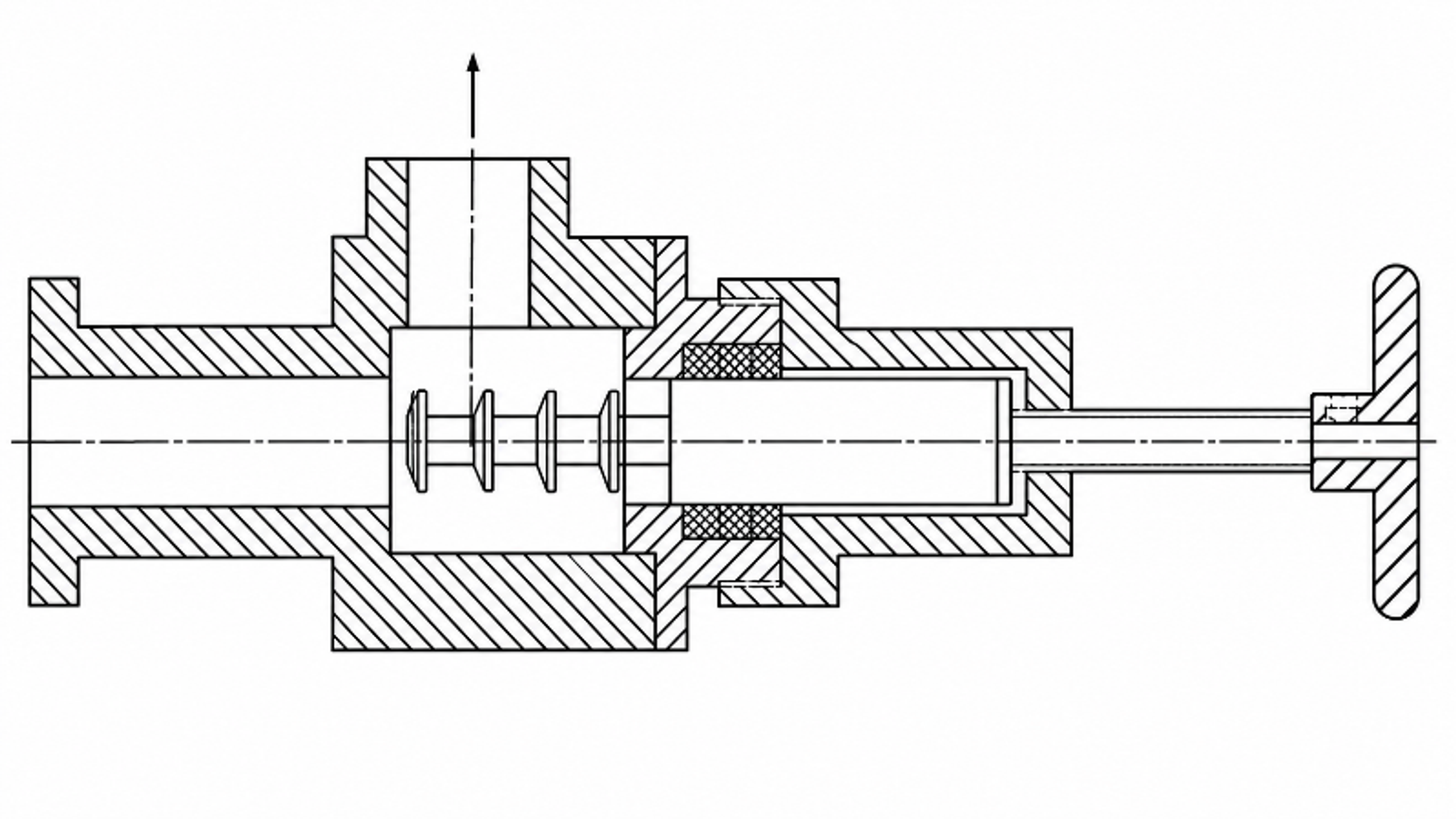
Figure 3. Adjustable multistage baffle cavitation device [14].
For abrasive or contaminated fluids, plates should be removable from a pressure rated spool and should include positive orientation features so that the same face is installed upstream after cleaning. Hard coatings can delay erosion, but coating delamination may contaminate the product. Erosion inspection should therefore be included in the test program, using mass loss, profilometry, microscopy, or elemental analysis of the processed liquid. An orifice device should not be selected solely because it produces a low measured cavitation number; the practical optimum lies between weak inception and excessive vapor loading that shields collapse events and increases vibration or unstable flow [2].
2.2 Venturi Based Devices
A Venturi cavitator uses a converging section, a throat, and a diffuser. The converging section accelerates the liquid while limiting abrupt separation. Cavitation begins immediately downstream of the throat, and the diffuser controls pressure recovery and the location of collapse. Compared with a sharp orifice, a properly designed Venturi generally has lower permanent pressure loss for the same flow and can provide a longer, more spatially distributed cavitation zone. The device is therefore attractive for continuous treatment where pumping energy, erosion, and cleanability are important [6].
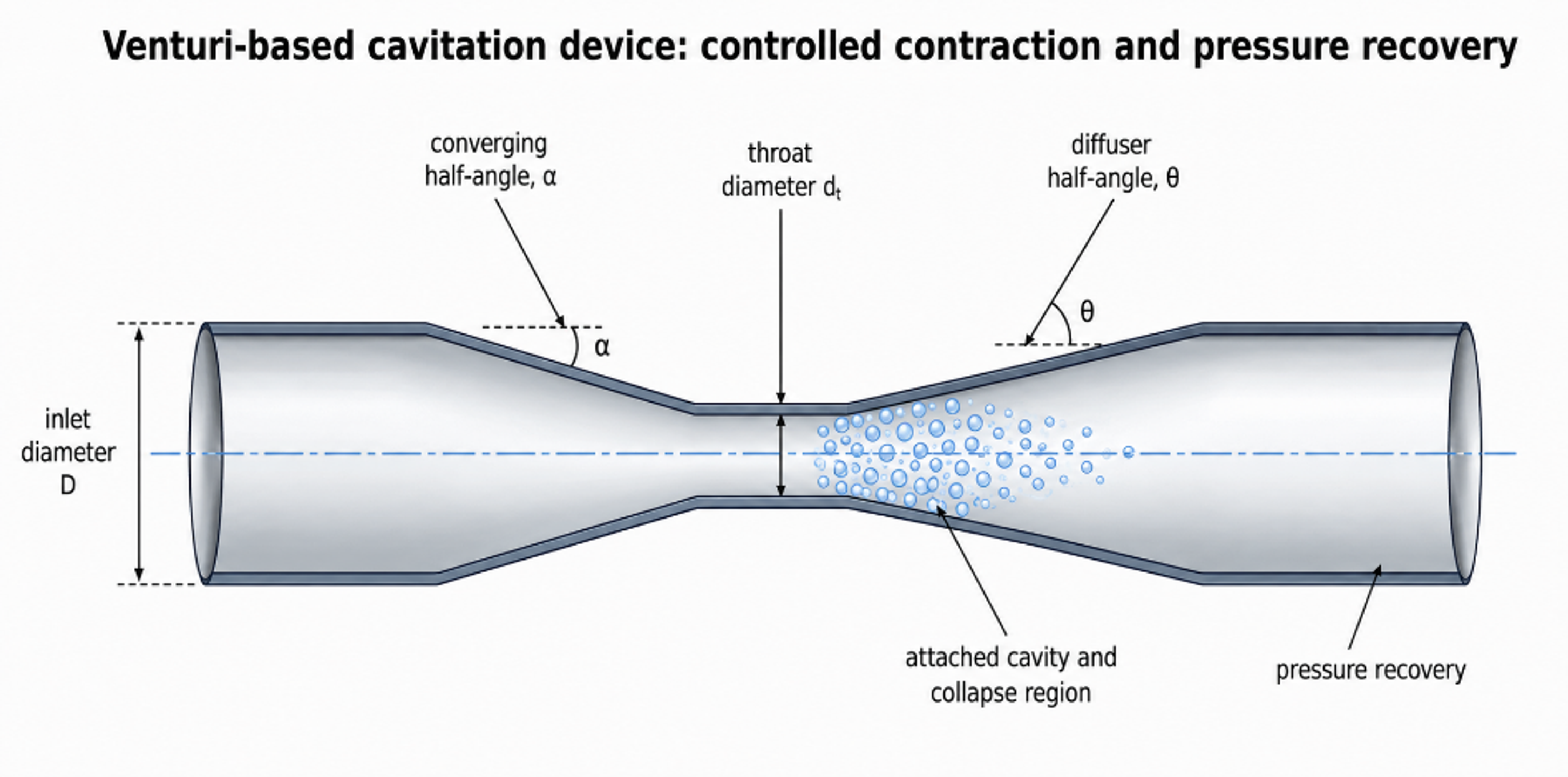
Figure 4. Venturi based cavitation device with controlled contraction, throat, and diffuser [58].
A useful, idealized flow relation for a Venturi is:
At is throat area and β is the throat to pipe diameter ratio. The discharge coefficient accounts for friction, nonuniform velocity, and deviations from ideal reference station assumptions. For cavitation service, the hydraulic calculation must be supplemented by an assessment of minimum pressure, vapor volume fraction, diffuser separation, and transient pressure history. Computational studies show that diffuser angle has a stronger effect on inception and cavity evolution than throat length over many practical ranges because an aggressive diffuser can separate and sustain an unsteady vapor cloud [6].
A long throat increases residence time at low pressure but also adds friction and can allow cavities to coalesce. A short throat minimizes length but may make inception sensitive to small machining errors. Diffuser angles that are too large create separation and a sudden recovery similar to an orifice; angles that are too small increase equipment length and wall area. The optimum is application dependent. For emulsification and particle processing, a sustained cavity cloud may be desirable. For oxidation, a pressure history that produces repeated intense collapses may be more important than total visible vapor volume. In either case, throat surface finish, circularity, concentricity, and transition radii should be treated as controlled dimensions [6].
Table 4. Venturi design variables.
| Variable | Primary influence | Engineering note |
|---|---|---|
| Converging angle | Acceleration profile and upstream separation | Avoid abrupt shoulders unless intentional pre separation is part of the design. |
| Throat diameter or slit dimensions | Velocity, inception pressure, solids passage, pressure drop | Use hydraulic diameter for noncircular throats and report aspect ratio. |
| Throat length | Low pressure residence time, wall interaction, friction | Specify L/d and internal surface finish. |
| Diffuser angle and length | Pressure recovery, cloud shedding, collapse location, permanent loss | The stated angle must define included or half angle. |
| Outlet/backpressure | Collapse pressure and axial position of the recovery zone | Use an independent downstream control element when mapping the operating envelope. |
| Pressure reference positions | Calculated Δp, σ, and inferred recovery | Report axial distances from the throat and the pressure reference convention. |
Venturi devices are normally easier to clean than dense multihole plates because the minimum passage can be made larger. For sanitary service, crevice free construction, drainability, material traceability, elastomer compatibility, and clean in place validation are as important as cavitation performance. For fibrous suspensions, a slit throat or a large hydraulic diameter may be preferred, provided that the required velocity is maintained. Scale up should preserve the shape ratios and the pressure recovery profile, not simply the throat velocity. The effect of wall roughness and manufacturing method becomes more important when small devices are enlarged or fabricated by additive manufacturing [2, 3, 6-9].
2.3 Bluff Body Based Devices
Bluff body cavitation devices generate a separated wake downstream of an obstruction, an annular gap around a body, or an impinging jet directed toward a target. Cavities form within low pressure shear layers and coherent vortices and collapse as the wake entrains surrounding liquid or encounters a high pressure stagnation zone. The body may be spherical, conical, disk shaped, stepped, slotted, or streamlined with an intentional separation edge. Geometry offers more freedom than a simple plate because the restriction ratio and wake topology can be adjusted independently [11, 12, 17].
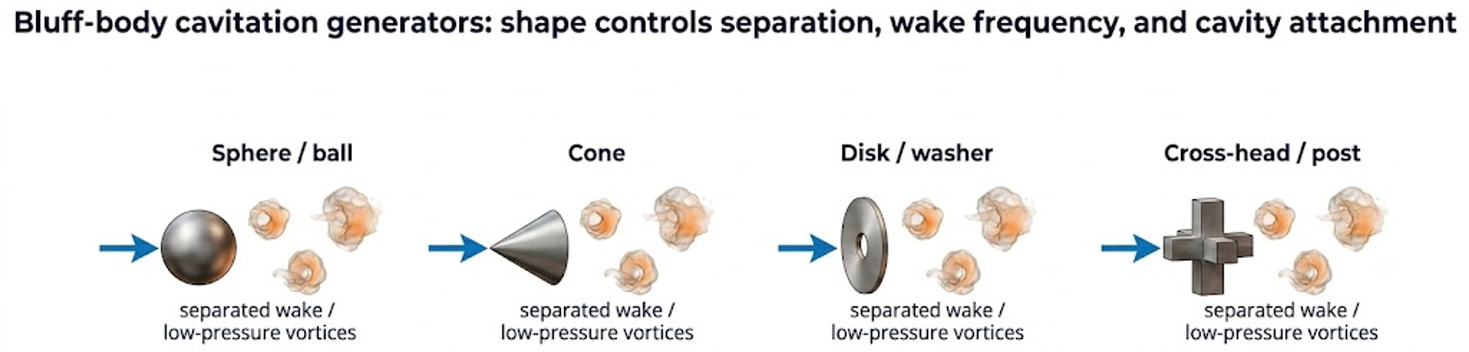
Figure 5. Representative bluff body cavitation generators. Body shape controls separation, wake frequency, and cavity attachment [58].
The characteristic shedding frequency may be represented by the Strouhal number:
where fs is shedding frequency, D is a characteristic body dimension, and U is approach velocity. Periodic shedding can create repeated pressure pulses without a rotating element. The frequency is not fixed by geometry alone; it changes with Reynolds number, blockage ratio, cavitation extent, and upstream turbulence. When a support stem is required, its wake and structural vibration must be considered as part of the reactor rather than as a passive mounting detail.
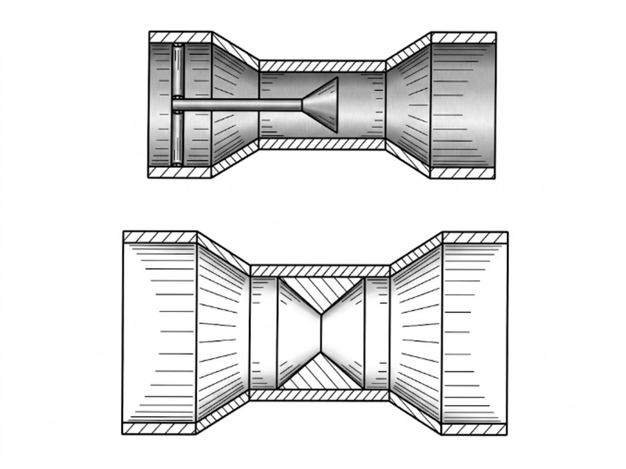
Figure 6. Conical and Venturi type bluff body arrangements for controlled local constriction [11].
A centered bluff body can produce an annular high velocity region while retaining a large gross flow area. Interchangeable bodies permit the same housing to be used for different viscosities or products. The body position can also be made adjustable, but the adjustment mechanism must be rigid under pulsating load and must not create an uncleanable cavity. The principal erosion risk occurs where an attached cavity collapses close to the body or wall. A replaceable sacrificial body is often preferable to relying on a permanent coating [11-14].
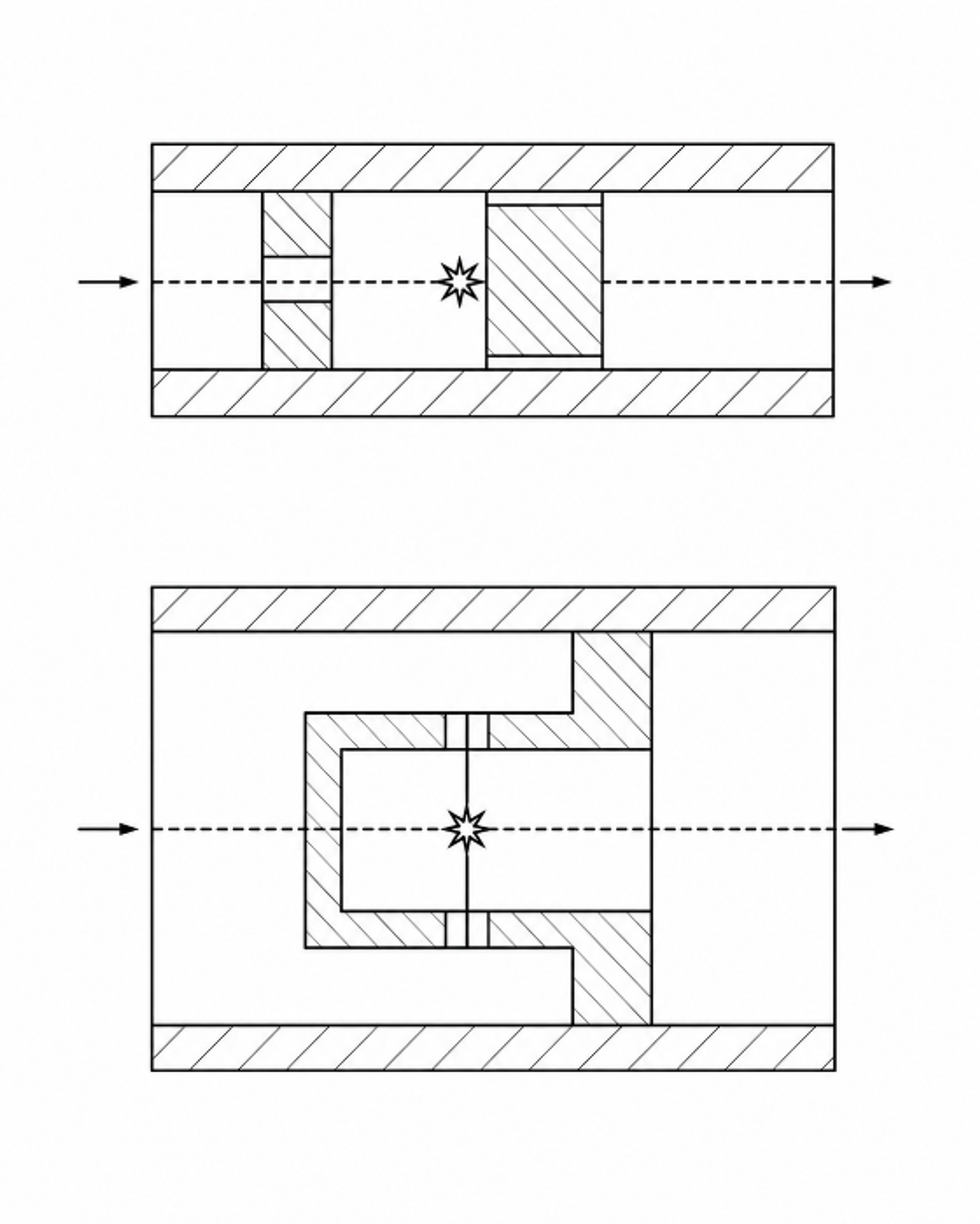
Figure 7. Impact body cavitation concept in which a bubble laden liquid jet collides with a target to force collapse under a selected stagnation pressure [17].
Impact body designs intentionally separate cavity generation from forced collapse. The distance between the restriction and target controls cavity growth time and the fraction of cavities that reach the impact zone. Target angle, impact area, and stagnation pressure determine collapse loading. Such systems can generate intense local treatment but require careful evaluation of target erosion, noise, pressure pulsation, and the possibility of product contamination. They are most defensible when the target is replaceable, the flow path is inspectable, and the process benefit is quantified per unit of measured electrical energy [17].
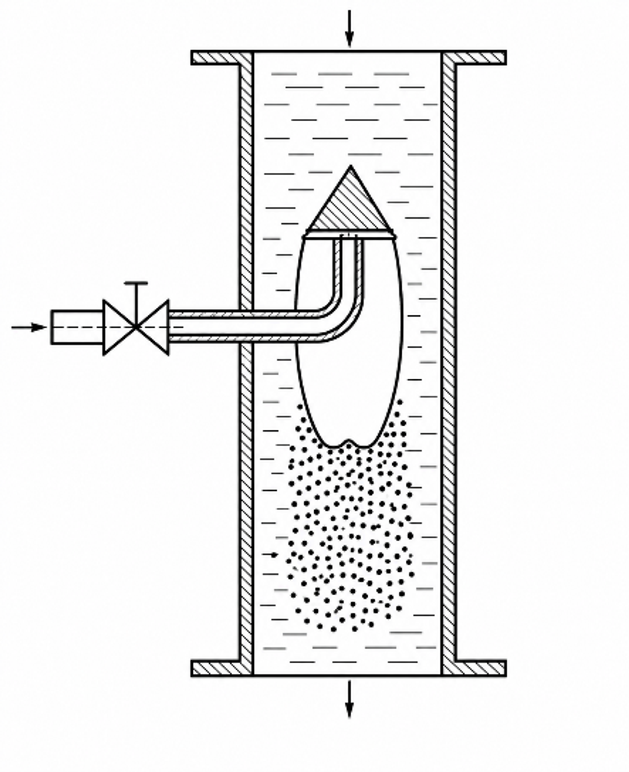
Figure 8. Historical cavitation reactor concept with auxiliary liquid injection into the boundary layer around a cavitator [18].
Historical reactor concepts also used auxiliary liquid injection into the boundary layer surrounding a cavitator to modify nuclei supply and collapse behavior. Such designs illustrate an enduring engineering principle: a secondary stream can control gas content, temperature, reactant concentration, or local turbulence independently from the main flow. Modern implementations should meter the secondary flow, quantify its effect on total energy and mass balance, and prevent backflow into the injection system [18].
2.4 Vortex Based Cavitation Devices
Vortex devices introduce liquid tangentially into a chamber so that angular momentum creates a low pressure core. Cavitation forms near the axis and is transported toward an axial or radial outlet where pressure recovers. Because the most intense vapor region can remain in the fluid core, swirling devices can reduce the probability of collapse directly on a wall. Experiments comparing linear and swirling cavitators have shown that swirl can relocate the cavity without an inherent energy penalty when the devices are compared on a matched hydraulic basis [4, 5].
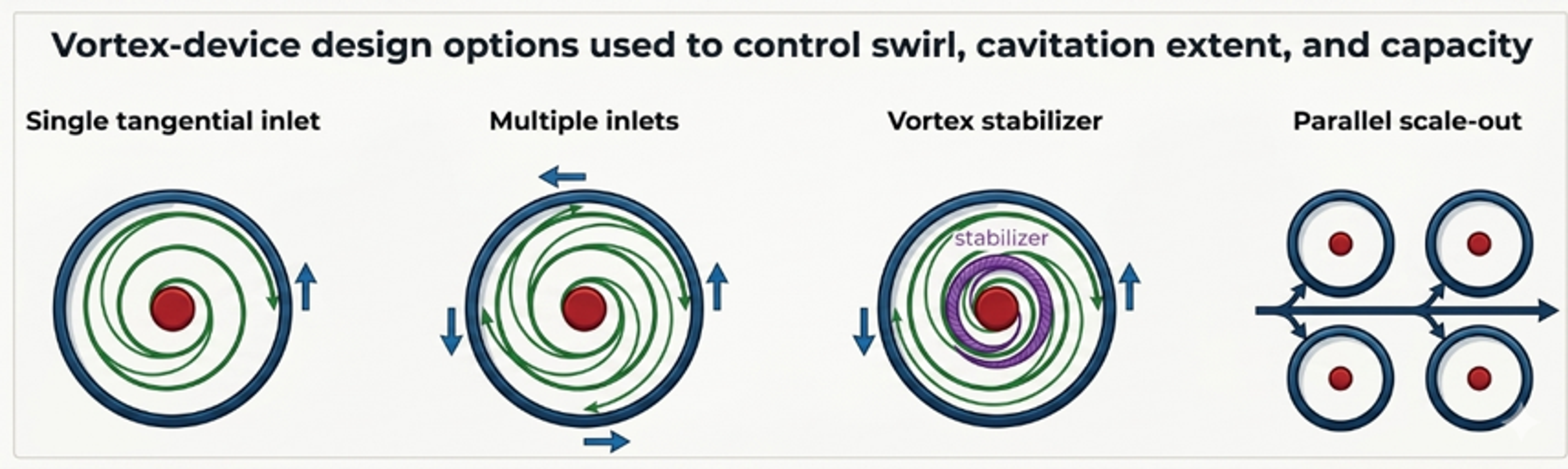
Figure 9. Vortex device design options are used to control swirl, cavity extent, symmetry, and capacity [58].
The essential geometric variables are chamber diameter and height, tangential inlet area and orientation, number of inlets, outlet throat diameter and length, chamber aspect ratio, and any vortex stabilizer or central body. A single tangential inlet creates an asymmetric precessing core. Multiple inlets can improve symmetry and throughput, although manifold design becomes more complex. The outlet must be large enough to avoid excessive total pressure loss but small enough to preserve the swirl strength needed for a low pressure core. Chamber modifications that increase vapor volume do not automatically improve an application, because particles or droplets may bypass the effective collapse region [3, 7-9].
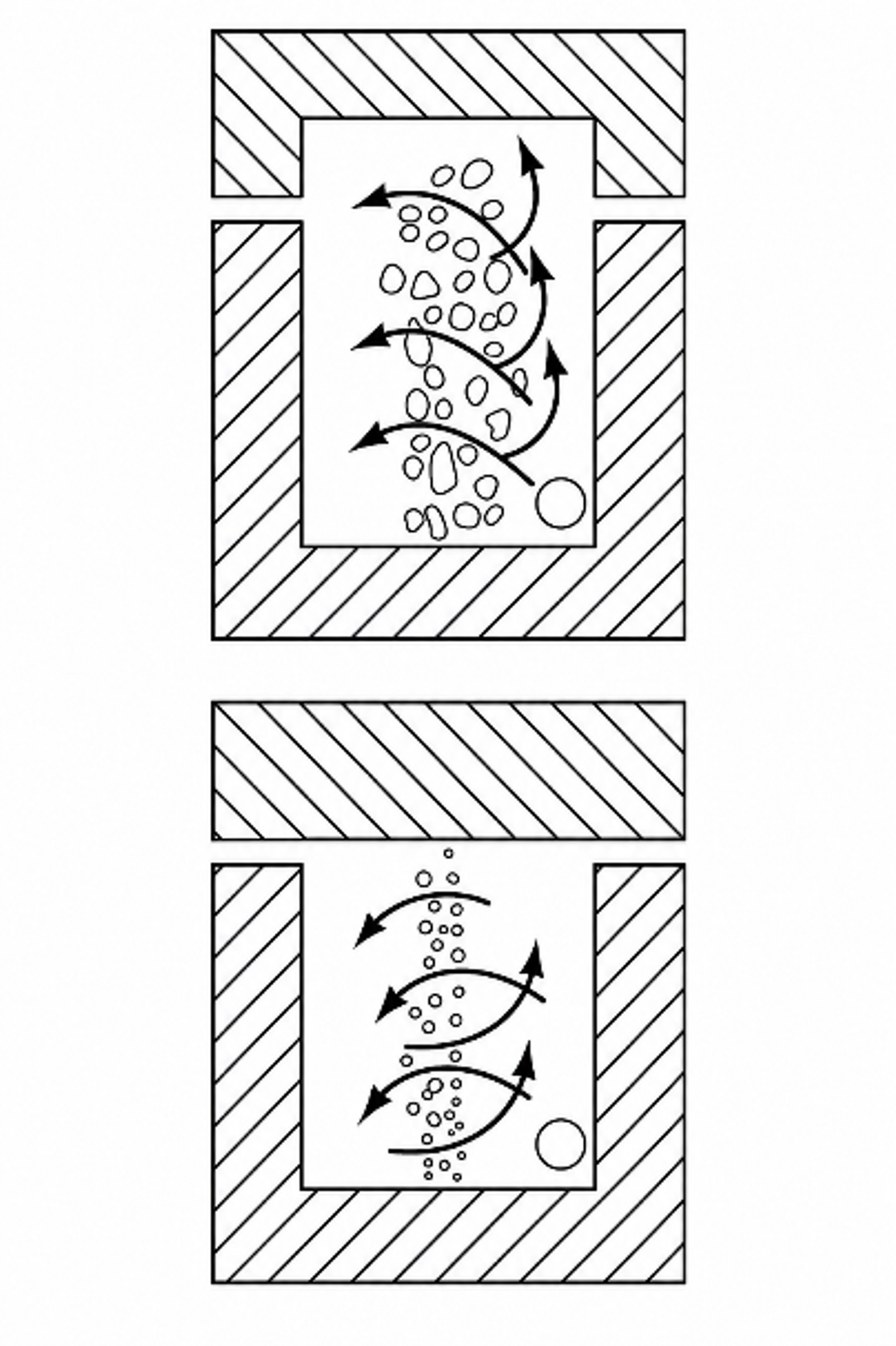
Figure 10. Tangentially fed vortex cavitation chamber with alternative open and closed cavity configurations [15].
Vortex devices are particularly attractive for suspensions and fibrous materials because the minimum clearances are commonly larger than in high pressure homogenizers. Their low wall erosion potential does not eliminate material risk: process cavities, recirculation zones, and outlet recirculation can still create localized attack. Transparent development sections and computational fluid dynamics can help locate these zones before metal construction. For industrial service, the chamber should be drainable and should avoid dead regions where solids can settle during shutdown [3, 4, 7-9, 15].
Table 5. Static device comparison for equipment selection.
| Criterion | Orifice | Venturi | Bluff body | Vortex |
|---|---|---|---|---|
| Fabrication | Simplest plate or cartridge | Longer machined or fabricated spool | Replaceable body and supports | Tangential chamber and manifold |
| Permanent pressure loss | Usually, high | Usually lower for controlled recovery | Moderate to high, geometry dependent | Moderate, with strong dependence on outlet |
| Blockage tolerance | Low for small multihole plates | Moderate to high with large throat | High if annular gap is large | High because of open chamber |
| Erosion control | Collapse may occur near plate or wall | Diffuser can move collapse downstream | Sacrificial body or impact target possible | Cavity can be retained in fluid core |
| Scale strategy | Increase holes, area, stages, or parallel units | Geometric scale up or parallel trains | Increase body and annular gap or use multiple bodies | Geometric scale up, multiple inlets, or parallel scale out |
| Best use | Screening, oxidation, disintegration, compact retrofits | Energy conscious continuous processing | Wake driven treatment and forced collapse concepts | Low clogging continuous processing and emulsification |
2.5 Opposed Vortex, Annular, and Multistage Flow Through Devices
Several static architectures extend the basic orifice, Venturi, bluff body, and vortex concepts by separating cavity generation from collapse or by repeating the pressure cycle within one housing. Their common objective is to control not only whether cavitation occurs, but also the cavity residence time, collapse pressure, interfacial contact pattern, and number of treatment zones per pass. The supplied patents and promotional materials illustrate four representative approaches: a two chamber pressure controlled jet, opposed or cascaded vortex nozzles, an annular tangential jet vortex chamber, and a long multistage low pressure reactor [28, 29, 32, 34, 35].
In a pressure controlled two chamber device, liquid is accelerated through a localized restriction from a first chamber at pressure p₁ into a second chamber maintained at pressure p₂. The jet dynamic pressure provides a convenient hydraulic scale:
where is the characteristic cavitating jet velocity. US Patent 5,971,601 further discloses a pressure ratio condition intended to force collapse in the second chamber:
The numerical boundary in Equation (13) is patent specific operating teaching rather than general cavitation law. Its engineering value is the explicit separation of a high velocity generation zone from a controlled static pressure collapse zone. A downstream resistance or control valve fixes p2 and therefore moves the collapse field independently from the upstream pump pressure. This arrangement can provide strong dispersion, but it also places a premium on pressure rated construction, erosion inspection, noise control, and stable backpressure regulation [29].
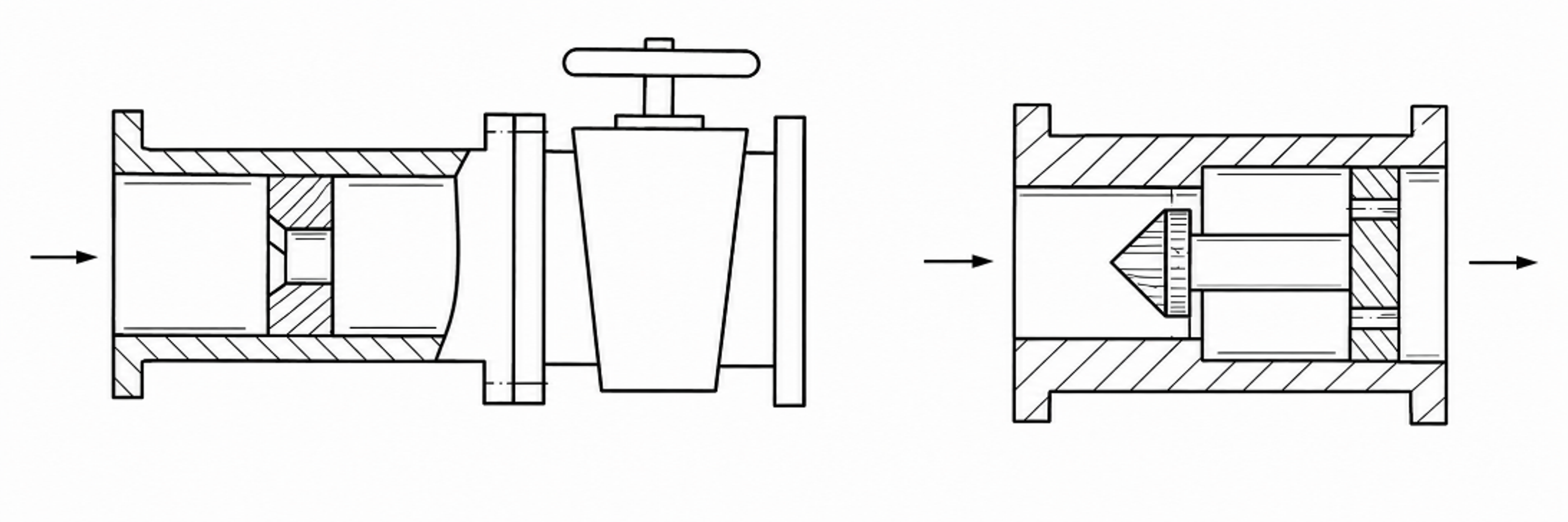
Figure 11. Two chamber cavitation jet arrangements with downstream pressure control and alternative cylindrical or annular restrictions [29].
Opposed vortex systems divide the feed into two branches and direct rotating streams toward a common collision chamber. In the disclosed emulsification system, cascaded vortex nozzle blocks accelerate and rotate the streams before they meet approximately at the chamber midpoint. This architecture combines swirl, jet impingement, rapid pressure fluctuation, and interfacial renewal. The manifold must divide flow symmetrically; otherwise, one jet penetrates the opposing nozzle and shifts the treatment zone. Balanced branch geometry, a removable nozzle cartridge, and an inspectable collision chamber are therefore important design features [28].
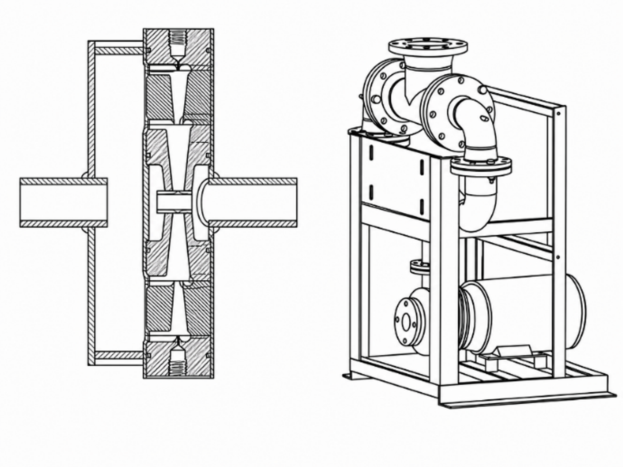
Figure 12. Opposed vortex fluid treatment system and pump driven skid architecture [28].
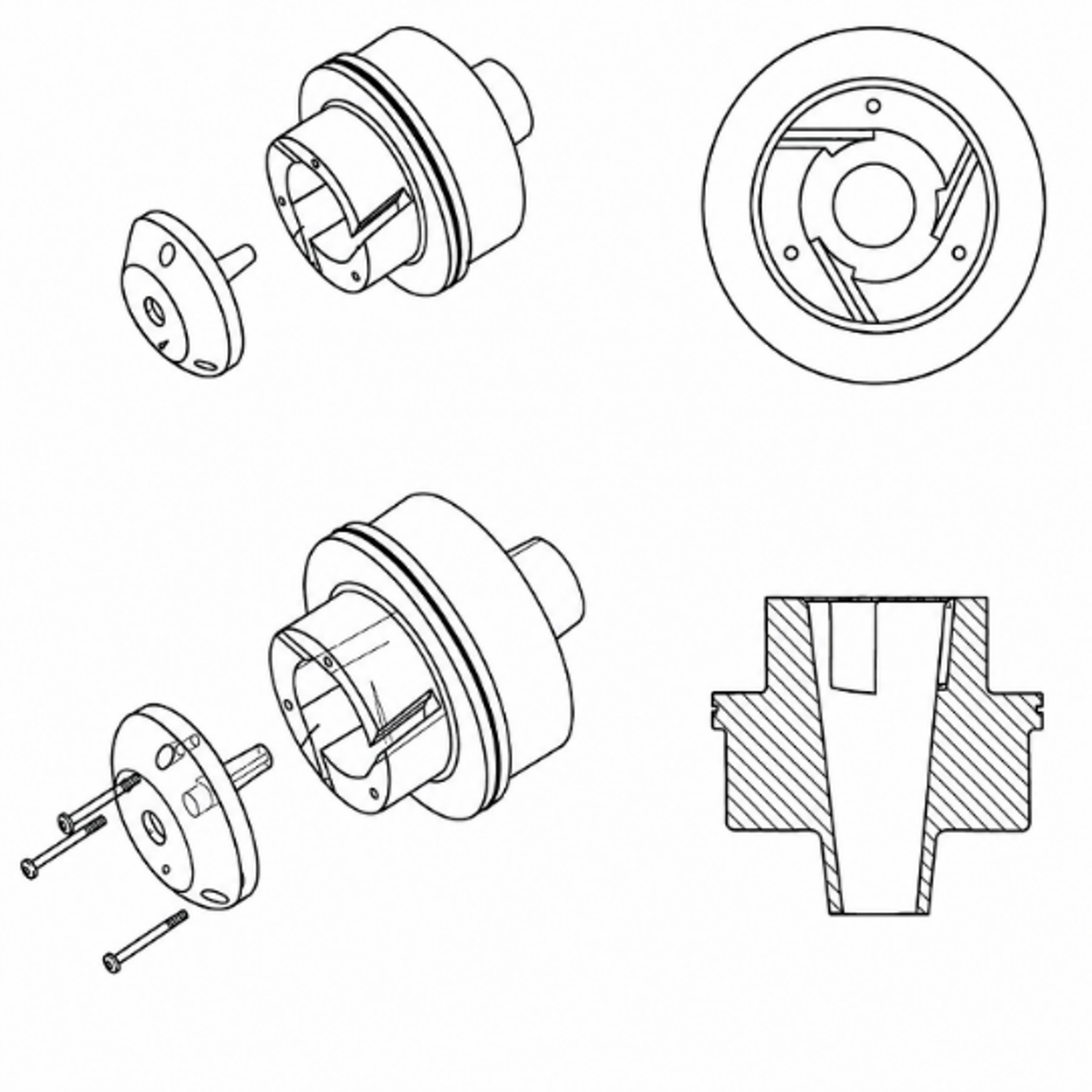
Figure 13. Exploded, end, and sectional views of a tangential vortex nozzle used in an opposed nozzle treatment chamber [28].
An annular tangential jet device uses slot openings in a cylindrical insert to divide one primary flow into opposed secondary jets. Deflection along the housing wall creates a rapidly rotating annular cavity, while axial discharge exposes the bubble laden liquid to a higher static pressure. Compared with a small multihole plate, the gross passage can be larger, and the low pressure region can remain in the liquid core. Design variables include slot number, slot width, tangential orientation, annular gap, cavity length, outlet diameter, and the axial position of the discharge plane [32].
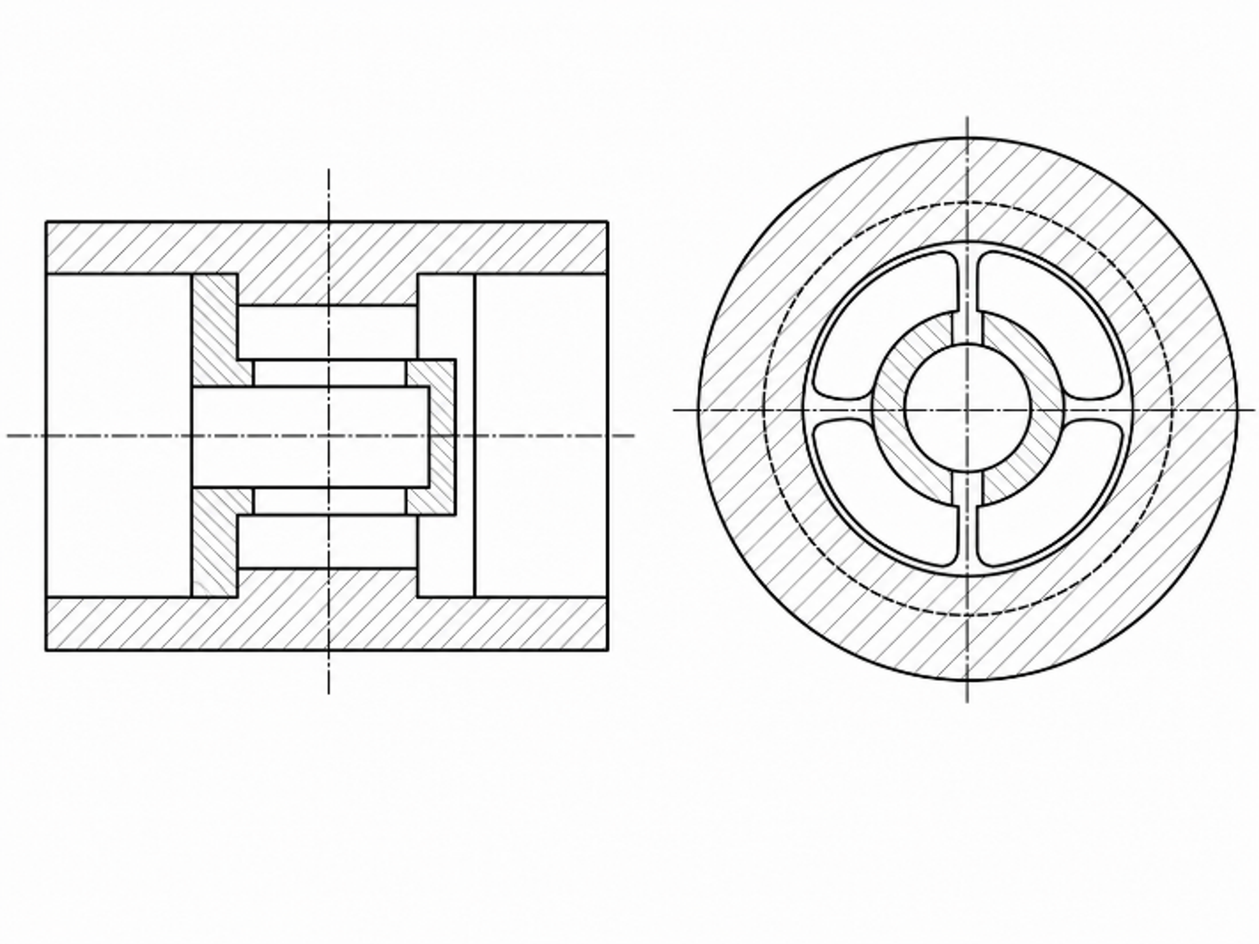
Figure 14. Static annular vortex cavitator with tangential slot jets and axial discharge [32].
The supplied CaviTune Low Pressure Nano Reactor material presents a long inline body containing multiple sequential flow cells. The concept is promoted as a no moving parts, low pressure, single stage or multistage reactor whose geometry is selected with CFD, structural analysis, and test data. From an engineering perspective, its principal advantage is the ability to distribute pressure loss and cavity exposure over many short cells rather than one severe restriction. The corresponding risks are cumulative permanent loss, manufacturing tolerance accumulation, trapped volume between stages, solids deposition, and difficulty verifying the pressure history inside each cell [34, 35].
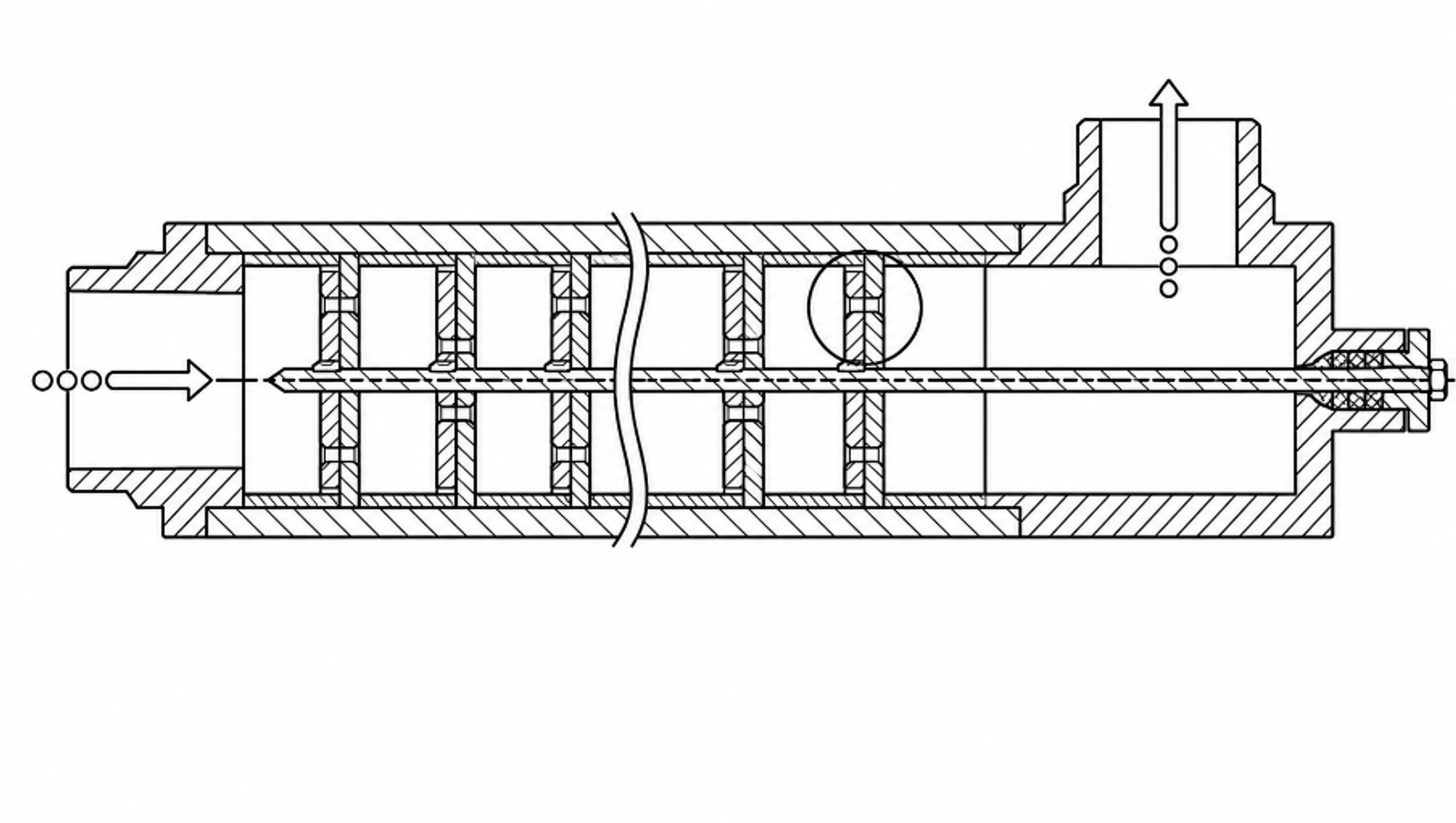
Figure 15. A multistage CaviTune Low Pressure Nano Reactor [34].
Table 6. Advanced static cavitation architectures and design checks.
| Architecture | Pressure history concept | Potential strengths | Critical verification |
|---|---|---|---|
| Two chamber controlled collapse [29] | Localized jet generation at p1 followed by collapse under controlled p2 | Independent adjustment of generation and collapse zones; replaceable restriction | Pressure ratio, jet residence time, downstream erosion, valve stability, noise |
| Opposed vortex nozzles [28] | Counter rotating or cascaded streams collide in a common chamber | Large interfacial renewal, compact manifold, optional additive injection | Branch flow symmetry, nozzle erosion, inspectability, pulsation and support loads |
| Annular tangential slot vortex [32] | Tangential jets establish a low pressure annular vortex followed by axial recovery | Open passages, wall offset vapor core, series staging possible | Slot tolerance, vortex symmetry, outlet recovery, solids deposition during shutdown |
| Multistage low pressure inline reactor [34,35] | Repeated short pressure drop and recovery cells in one body | Distributed treatment dose, no moving cavitation element, modular length | Stage to stage pressure map, cumulative loss, cleanability, tolerance stack and fouling |
For all advanced static devices, scale up should preserve the local geometry of each generating cell and use parallel scale out before increasing passage dimensions beyond the validated range. Scale up evidence should include branch flow balance, total electrical pump power, gas condition, temperature history, product distribution, and inspection findings. A longer device with more visible vapor is not necessarily more effective; the decisive quantity is the product transformation achieved per unit of measured energy and per unit of equipment wear.