
Technical publication
Back to publications
Reactors & equipment
Hydrodynamic Cavitation Technological Equipment
okozyuk.com
Published
Read complete publication for whole-document Find and printing. Browser Find and native printing on this reader include only loaded content.
1. Introduction
Hydrodynamic cavitation equipment is intentionally designed to create and then terminate low pressure regions in a liquid stream. This objective distinguishes process cavitators from pumps, valves, propellers, and hydraulic machinery in which cavitation is normally an unwanted cause of erosion, noise, vibration, and performance loss. In a process reactor, the pressure time history is selected so that bubble collapse, microjets, shock waves, interfacial renewal, and high local strain rates can be used for mixing, emulsification, cell disruption, extraction, oxidation, crystallization, heating, and other transformations [3-6, 36].
The cavitation generating element is only one part of the technological system. Pump selection, suction conditions, upstream flow development, dissolved and entrained gas, temperature control, downstream backpressure, recirculation volume, residence time distribution, and sampling practice all alter the state experienced by the processed material. For rotating systems, the drive, shaft, seals, bearings, rotor balance, clearances, and control logic become equally important. Consequently, a device should be specified by its full geometry and operating envelope rather than by a nominal cavitation number, pressure drop, or rotational speed alone [4-8, 36].
Equipment selection begins with the required product attribute and the allowable process constraints. A multihole orifice can provide compact, intense pressure recovery but may clog or erode. A Venturi can reduce permanent loss but requires controlled diffuser geometry. Vortex devices can retain the vapor core away from walls and tolerate larger passages, whereas dynamic rotors provide adjustable intensity and high throughput at the cost of mechanical complexity. Advanced architectures combine staging, swirl, impingement, or deliberately separated growth and collapse zones. The following sections compare these options on a common basis of geometry, pressure history, throughput, energy, maintainability, and scale up evidence.
1.1 Equipment Function and Process Architecture
A hydrodynamic cavitation unit is a coupled hydraulic, mechanical, and process system. The cavitation element creates the local pressure history, while the pump, piping, control valve, tank, gas handling, and heat removal system determine the boundary conditions imposed on that element. Two geometrically identical cavitators can therefore produce different results when installed with different upstream straight lengths, suction conditions, backpressure, dissolved gas content, piping volume, or recirculation topology. Equipment selection must begin with the required product transformation and the acceptable operating envelope rather than with a nominal cavitation number alone [1-5].
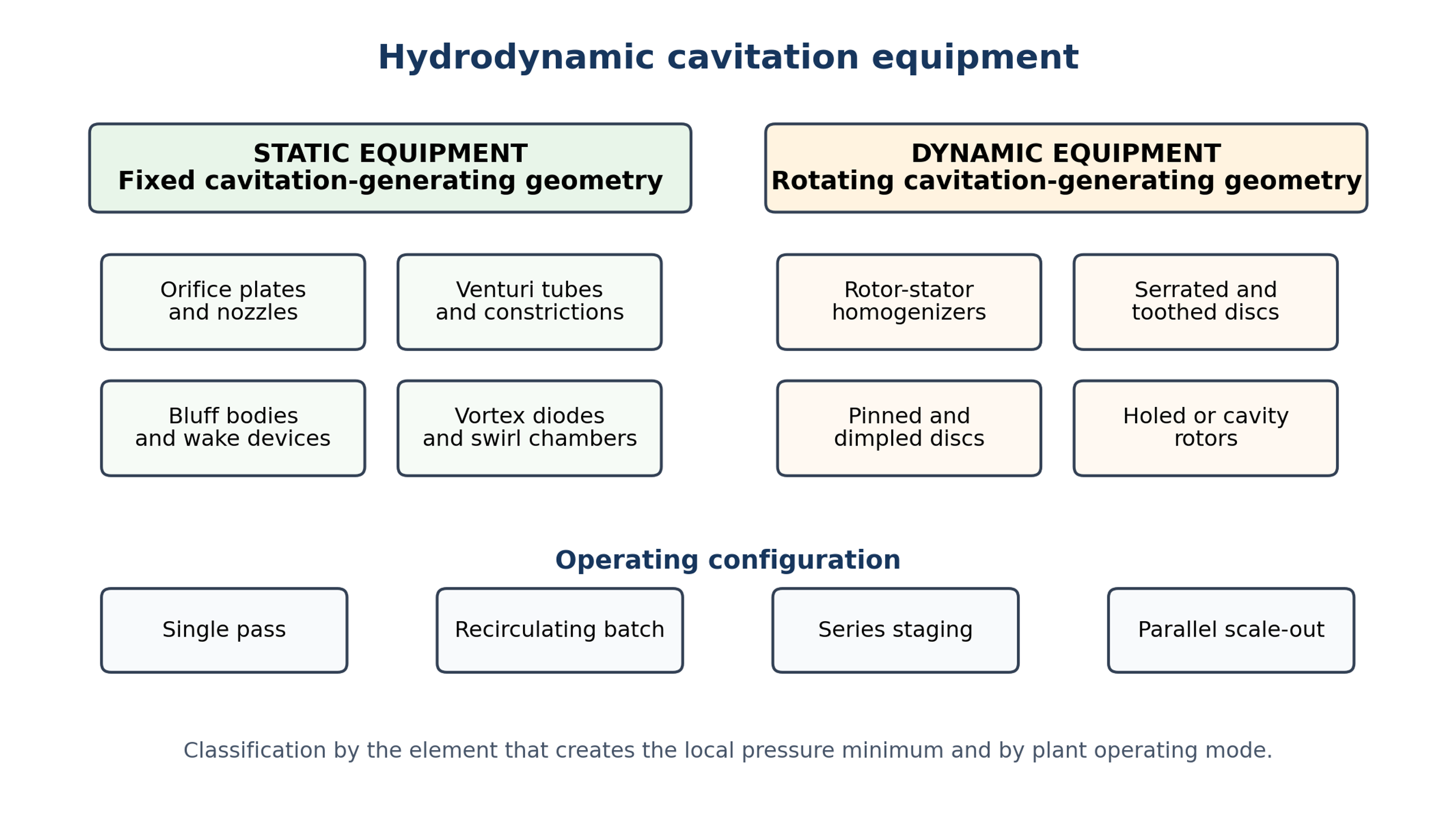
Figure 1. Classification of hydrodynamic cavitation equipment by the element that creates the low pressure region and by operating mode [58].
Static devices have no moving cavitation generating element. The pressure reduction is produced by a fixed restriction, a separated wake, or a swirling core. Their advantages include simple fabrication, low mechanical maintenance, straightforward high pressure containment, and convenient installation in existing pipelines. Their principal limitations are the hydraulic power required to drive the pressure drop, possible clogging of small passages, erosion near attached cavities, and a broad exposure distribution in recirculation systems. Dynamic devices use rotation or oscillation to generate rapid pressure fluctuations, wakes, gap flows, or cavity formation inside moving recesses. They may combine pumping, mixing, heating, and cavitation in one machine, but introduce bearings, seals, shaft alignment, vibration, rotor balance, motor sizing, and maintenance requirements [4, 6].
A single pass installation is preferred when the treatment target can be achieved in one exposure and when a narrow residence time distribution is required. A recirculation loop is useful for development work because it permits controlled accumulation of treatment dose, but the nominal pass count does not imply that every fluid element has received the same number of exposures. Series staging increases the number of cavitation zones per pass and may permit intermediate pressure recovery. Parallel scale out raises capacity while preserving the geometry and operating state of a validated device. A practical process loop includes a drainable hold tank, a pump selected for the required flow pressure curve, backpressure control, sampling provisions, and, when temperature rise is not part of the intended duty, a heat exchanger [2, 3].
1.2 Hydrodynamic and Cavitation Design Quantities
The Rayleigh Plesset equation provides the classical starting point for interpreting the radial motion of an isolated spherical cavity in an infinite liquid. Although industrial cavitation is cloud like, turbulent, nonspherical, and frequently close to walls, the equation identifies the competing effects of pressure, inertia, surface tension, and viscosity [1, 2].
Here R is cavity radius, is pressure inside the cavity, is the far field liquid pressure, ρ is liquid density, γ is surface tension, μ is dynamic viscosity, and overdots denote time derivatives. Equipment design does not normally solve this equation for every cavity; instead, it uses the equation to interpret how pressure time histories created by the equipment affect growth and collapse intensity.
The average velocity through any defined cross section follows from continuity:
where Q is volumetric flow rate, A is flow area, and v is mean velocity. For a steady incompressible stream between stations 1 and 2, the practical energy balance is:
In Equation (3), p is static pressure, z is elevation, g is gravitational acceleration, and is the irreversible head loss. In a cavitation device, the minimum local pressure can be substantially lower than the pressure measured by a wall tap; therefore, measured inlet and outlet pressures describe system performance but do not directly reveal the minimum pressure inside a separated jet, wake, or vortex core [4-6].
A commonly reported operating parameter is the cavitation number:
The reference pressure and reference velocity must be defined explicitly. Appropriate reference locations and velocities differ among orifices, Venturis, vortex devices, and rotating machines. A value reported without these definitions is not reproducible. Cavitation inception often occurs when the locally defined number is of order unity, but inception and useful operation depend strongly on geometry, nuclei population, temperature, gas content, and pressure recovery [2-6].
The Reynolds, Euler, and Weber numbers used in equipment comparison are:
In these expressions, D or d is a stated characteristic length. Re characterizes the ratio of inertial to viscous effects; Eu expresses pressure drop relative to inertial forces; and We compares inertia with interfacial tension. These groups are necessary but not sufficient for scale up because cavity size distributions, exposure time, gas transport, and collapse location can change while Re, Eu, We, and σ are nominally matched [2-4, 7-9].
Table 1. Equipment family selection matrix.
| Equipment family | Primary low pressure mechanism | Typical strengths | Primary design risks |
|---|---|---|---|
| Orifice plate or nozzle | Jet acceleration, vena contracta, separation downstream of sharp or shaped openings | Low cost, easy replacement, multihole flexibility, high pressure capability | Permanent pressure loss, clogging, plate erosion, sensitivity to edge and thickness |
| Venturi constriction | Acceleration through a converging section and throat followed by controlled pressure recovery | Lower permanent loss, distributed cavity, good cleanability with large throat | Diffuser separation, fabrication tolerance, longer installed length |
| Bluff body or impact target | Separated wake, vortex shedding, stagnation impact, or annular gap | Interchangeable geometry, open flow area, tunable wake frequency | Attached cavity erosion, vibration, solids lodging behind supports |
| Vortex device | Tangential momentum creates a low pressure swirling core | Cavitation displaced toward fluid core, low clogging tendency, compact scale out | Precessing core, asymmetric flow, sensitivity to outlet and inlet geometry |
| Rotor or rotor stator | Blade wakes, moving restrictions, dimple or pin wakes, cyclic high low pressure exposure | High throughput, integrated mixing or pumping, adjustable by speed | Seals, bearings, balance, vibration, rotor wear, mechanical maintenance |
Table 2. Minimum data set for reproducible equipment tests.
| Category | Information to report |
|---|---|
| Geometry | Complete dimensions; number, shape, and orientation of restrictions; materials; surface finish; pressure reference locations; upstream and downstream lengths. |
| Hydraulics | Inlet, outlet, and backpressure; flow rate; pump type and speed; valve positions; batch and loop volumes; hold up; number of stages and nominal passes. |
| Liquid and dispersed phase | Density, viscosity, vapor pressure, temperature, surface or interfacial tension where relevant, solids loading, particle or droplet size, dissolved or entrained gas condition. |
| Energy | Measured electrical power, shaft power if available, hydraulic power, treatment time, specific energy, heat removed or retained, and uncertainty. |
| Product response | Full particle or droplet distribution, conversion or removal, stability, morphology, phase identity, replicate count, uncertainty, and sampling protocol. |
| Equipment integrity | Erosion, metal contamination, fouling, cleaning method, seal leakage, vibration, noise, and temperature history. |