
Technical publication
Back to publications
Other
Fabrication of High Performance Catalysts by Controlled Flow Cavitation
okozyuk.com
Published
Read complete publication for whole-document Find and printing. Browser Find and native printing on this reader include only loaded content.
1 Introduction
This article establishes the hydraulic definitions, energy boundaries, residence time expressions, uncertainty requirements, and scale translation principles needed to evaluate controlled flow cavitation for catalyst manufacture. The framework is then applied to the mechanisms, models, characterization methods, and acceptance criteria specific to catalyst synthesis and conditioning.
High performance catalyst manufacture requires simultaneous control across several length scales. The composition of a mixed precursor must remain uniform at the molecular or colloidal scale, primary crystallites must nucleate and grow within a defined size range, and weak agglomerates must remain recoverable without excessive hard sintering. Active metals and promoters must contact the support in the intended spatial arrangement. The structure formed during precipitation must also survive filtration, washing, drying, calcination, reduction, sulfidation, or other activation procedures.
Conventional stirred precipitation can produce high quality materials, but performance may be limited by local pH gradients, feed segregation, long micromixing times, broad residence time distributions, and aging before the slurry experiences intense mechanical treatment. Controlled flow cavitation (CFC) addresses these limitations by exposing a newly formed gel, hydroxide, carbonate, reduced metal, or support slurry to a pressure driven cavitation field immediately after formation. The short interval between chemical formation and hydrodynamic exposure is a defining feature because mixing and particle engineering occur while the intermediate remains soft, reactive, and susceptible to fragmentation [1-7].
Accordingly, CFC is best regarded as a synchronized reaction and particle engineering platform rather than as a cavitation device applied after synthesis. Pressure alone does not define the treatment condition. Material response depends on precursor chemistry, feed sequence, pH, temperature, restriction geometry, upstream pressure, pressure recovery, flow rate, dissolved gas, solids loading, viscosity, number of passes, and downstream stabilization. Identical nominal cavitation numbers can therefore produce different bubble populations and catalyst structures when these variables differ.
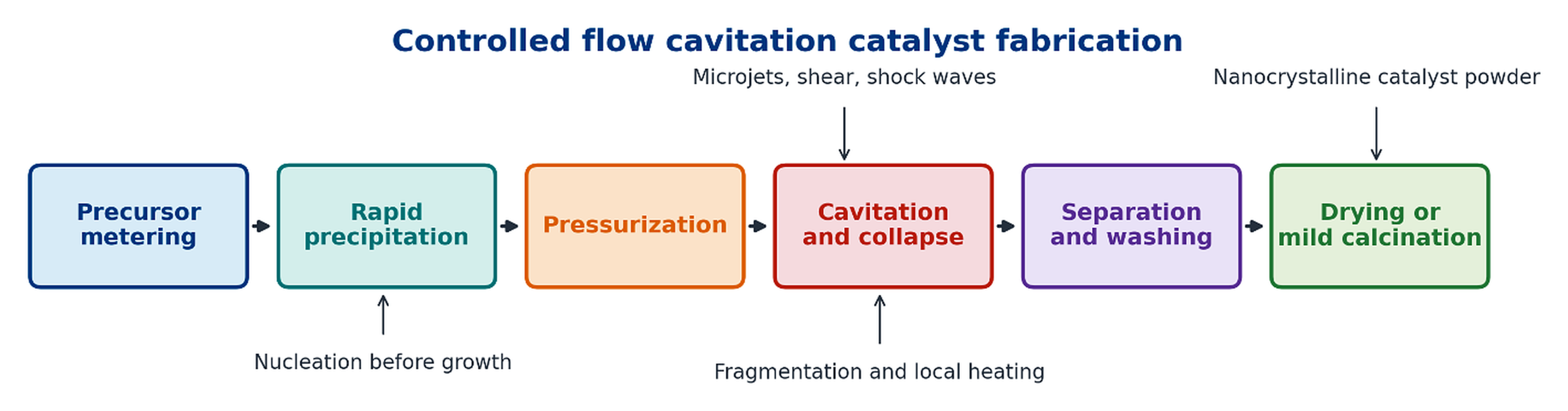
Figure 1.1. Integrated sequence for cavitation catalyst fabrication. [1-7].
Table 1.1. Evidence hierarchy for evaluating claims about CFC catalyst manufacture
| Evidence class | Typical measurements | What the evidence establishes | Principal limitation |
|---|---|---|---|
| Direct structural evidence | X ray diffraction, selected area electron diffraction, electron microscopy, BET area, chemisorption | Phase identity, crystallite size, morphology, dispersion, strain, and porosity after isolation | The isolated structure may differ from the catalyst under reaction conditions |
| Indirect process evidence | Pressure and flow records, precursor decomposition, rounded particles, bulk temperature rise | Compatibility with intense mixing, impact, localized heating, or accelerated conversion | Does not directly measure the pressure or temperature of individual collapse events |
| Catalytic evidence | Conversion, selectivity, intrinsic rate, turnover frequency, deactivation | Whether a defined catalyst performs better in a defined reaction | Must normalize loading, surface area, dispersion, transport, and activation history |
| Scale evidence | Mass balance, specific energy, run length, erosion, product statistics | Manufacturability, durability, and economic relevance | Laboratory pressure and throughput cannot be scaled by a single geometric ratio |
| Promotional or conceptual claim | Equipment literature, schematic mechanism, estimated local temperature | Useful hypothesis and development direction | Requires independent measurement and controlled comparison |
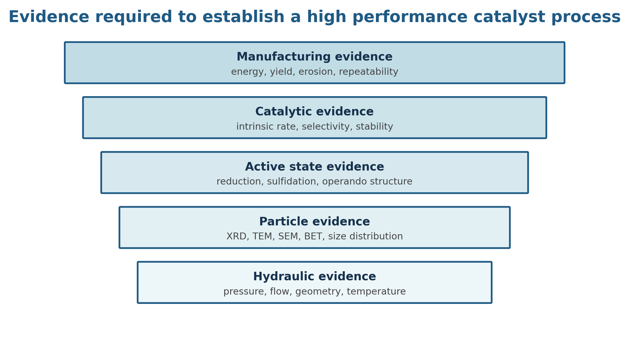
Figure 2.1. Evidence ladder for cavitation catalyst development. [29].