
Technical publication
Back to publications
Industrial applications
Design and Operating Principles of Rotor-Stator Mixers
okozyuk.com
Published
Read complete publication for whole-document Find and printing. Browser Find and native printing on this reader include only loaded content.
10. Effects of Design and Operating Parameters on Rotor-Stator Performance
Engineering design and selection of rotor-stator equipment require simultaneous consideration of working element geometry, flow hydrodynamics, material rheology, and thermal history. A technically sound specification begins by defining the desired transformation, such as deagglomeration, fine emulsification, or homogenization, and identifying the dominant mechanism responsible. Selecting equipment solely by installed motor power is methodologically inadequate: it may deliver vigorous bulk circulation without sufficient local shear stress, or very intense treatment of only a small portion of the material while leaving poor overall exchange and stagnant regions.
Different features of the working pair control distinct aspects of mixer performance:
-
Radial clearance: Reducing the gap increases nominal velocity gradient and local shear stresses but also raises flow resistance, reduces tolerance to accidental solids, and increases sensitivity to differential thermal expansion of the rotor and stator.
-
Open area and hole geometry: Changing the free area and profile of stator passages directly affects jet velocity, hydraulic losses, and the characteristic scales of turbulent eddies.
-
Number of repeating elements: Increasing the number of teeth, blades, or openings raises the passage frequency and high-frequency pressure modulation. However, pressure amplitude does not necessarily increase proportionally because throughput limits and hydrodynamic blockage also affect the flow.
-
Active radius: Changing working element diameter changes tip speed and centrifugal forces and therefore influences the overall power potential of the machine.
Where hydrodynamic cavitation or controlled phase transitions are the intended dominant mechanism, operating parameters such as static pressure, backpressure, and fluid temperature must be independently controlled to avoid unstable operation, excessive thermal degradation, or uncontrolled equipment erosion.
Table 10.1. Principal dimensionless criteria
| Criterion | Definition | Principal physical meaning |
|---|---|---|
| Rotor Reynolds number | Equation (9.4) | Balance of inertial and viscous effects at the rotor scale. |
| Gap Reynolds number Reg | Equation (9.5) | Balance of inertia and viscosity in the clearance. |
| Power number Po | Equation (9.7) | Dimensionless liquid power for geometric and dynamic similarity. |
| Flow coefficient Φ | Equation (9.8) | Pumping or flow rate normalized by rotor speed and diameter. |
| Pressure coefficient Ψ | Equation (9.9) | Pressure rise or loss relative to dynamic pressure at the rotor scale. |
| Cavitation number | Equation (9.17) | Pressure margin above vapor pressure relative to dynamic pressure. |
| Strouhal number St | Equation (9.22) | Oscillation frequency relative to a convective time scale. |
| Droplet Weber number Wed | Equation (9.29) | Turbulent deformation relative to interfacial tension. |
| Capillary number Ca | Equation (9.30) | Viscous deformation relative to interfacial tension. |
| Ohnesorge number Oh | Equation (9.31) | Effect of dispersed phase viscosity relative to inertia and capillarity. |
Table 10.2. Design parameters and expected effects
| Parameter | Typical effect of increasing the parameter | Possible adverse effect |
|---|---|---|
| Rotor speed | Increases tip speed, event frequency, power, shear, and turbulence. | Rapid heating, seal loads, vibration, erosion, and air entrainment. |
| Rotor diameter | Increases tip speed and sharply increases turbulent power at constant rpm. | Higher torque and mechanical stresses; scale up errors at constant rpm. |
| Smaller clearance | Increases nominal shear rate and pressure gradient. | Contact risk, resistance, heating, wear, and particle blockage. |
| Smaller stator openings | Increases edge length and jet velocity at fixed throughput. | Pressure loss, clogging, and reduced pumping capacity. |
| Additional stages | Increases accumulated mechanical exposure per pass. | Heating, pressure loss, cleaning difficulties, and overprocessing. |
| Higher backpressure | Can suppress cavitation and stabilize complete liquid filling. | Greater seal and housing loads, potentially more power or lower flow. |
| Higher temperature | Often decreases viscosity and interfacial tension. | Higher vapor pressure, cavitation tendency, and degradation rate. |
| Higher viscosity | Increases viscous stress at a given shear rate. | Lower flow, higher torque, and weaker turbulence. |
| Higher gas content | Increases nuclei and may promote earlier cavitation onset. | Foaming, reduced pumping, oxidation, and unstable power. |
| Higher solids loading | More particle contacts and greater solids mass per mixture volume. | Higher viscosity, plugging, abrasive wear, and incomplete wetting. |
10.1 Numerical Example and System Sensitivity Assessment
The following hypothetical numerical example concerns a recirculating process using a continuous liquid phase with properties close to those of water. It is provided solely to illustrate the engineering method; it is not an official specification or a performance guarantee for equipment from Scott Turbon, IKA, Silverson, Kinematica, or any other manufacturer.
The active deformation zone volume and the share of input power dissipated within that volume are assumed for sensitivity analysis rather than measured. Table 10.3 lists the adopted parameters for a model in which fluid properties and volumetric flow rate remain constant throughout the processing cycle.
Table 10.3. Assumed input data for the numerical example
| Quantity | Assumed value | Explanation |
|---|---|---|
| Rotor diameter D; speed n | 0.100 m; 3000 min⁻¹ | N = 50 s⁻¹; chosen to illustrate the operating condition. |
| Effective gap g; element count z | 0.50 mm; 24 | Relative gap velocity approximated by rotor tip speed. |
| Flow Q; tank volume VT; time t | 0.0020 m³·s⁻¹; 0.50 m³; 600 s | Constant-flow recirculation through an ideally mixed tank. |
| Active volume Va | 2.0 × 10⁻⁵ m³ | 20 mL; assumed averaging region, not a measured machine volume. |
| Density ρ; viscosity μ | 1000 kg·m⁻³; 0.0010 Pa·s | Newtonian liquid with constant physical properties. |
| Specific heat capacity cp | 4180 J·kg⁻¹·K⁻¹ | No phase transitions or heat removal in the temperature estimate. |
| Shaft power Ps; dissipated power Pdiss | 3.10 kW; 3.00 kW | 60 W mechanical losses and 40 W useful hydraulic power. |
| Pressure rise Δp | 20 kPa | Positive pressure rise at the specified flow rate. |
| Power dissipated in active zone Ploc | 2.10 kW | Assumed to be 70% of power dissipated in the liquid. |
| Reference pressure pref; vapor pressure pv | 150 kPa absolute; 2.34 kPa | Assumed values for the illustrative cavitation number. |
| Interfacial tension σi; coefficient CH | 0.030 N·m⁻¹; 0.725 | Illustrative inertial-range droplet scaling, not a calibrated prediction. |
At the specified shaft power, calculated torque is 9.87 N·m. Rotor tip speed is 15.71 m/s, nominal gap shear rate is 3.14 × 10⁴ s⁻¹, and element passage frequency is 1200 Hz. These are kinematic results, not measurements of local stress distributions. The rotor Reynolds number is 5.00 × 10⁵, and the gap Reynolds number at the assumed relative velocity is 7.85 × 10³.
Table 10.4. Calculated characteristics of the example
| Quantity | Calculated result | Equation |
|---|---|---|
| Rotor tip speed Ut | 15.71 m·s⁻¹ | (2.2) |
| Element passage frequency fp | 1200 Hz | (2.3) |
| Nominal gap shear rate | 3.14 × 10⁴ s⁻¹ | (9.1) |
| Rotor and gap Reynolds numbers | 5.00 × 10⁵; 7.85 × 10³ | (9.4), (9.5) |
| Torque T | 9.87 N·m | (9.6) |
| Power number Po; flow coefficient Φ | 2.40; 0.040 | (9.7), (9.8) |
| Pressure coefficient Ψ; hydraulic ratio | 0.80; 1.29% | (9.9), (9.10) |
| Nominal residence time in the active zone | 0.010 s | (3.1) |
| Mean equivalent pass count | 2.40 | (3.2) |
| Mean specific dissipation rate in the tank | 6.00 W·kg⁻¹ | (9.11) |
| Volumetric dissipation rate in the active zone | 1.05 × 10⁸ W·m⁻³ | (9.12) |
| Specific dissipation rate in the active zone | 1.05 × 10⁵ W·kg⁻¹ | (9.11), using Ploc and Va |
| Energy per unit volume per pass | 1.50 MJ·m⁻³ | (9.13) |
| Nominal accumulated batch dose | 3.60 MJ·m⁻³ | (9.14) |
| Adiabatic heating per pass; after 600 s | 0.359 K; 0.861 K | (9.15) |
| Reference cavitation number | 1.20 | (9.17) |
| Local Kolmogorov length η and time | 1.76 µm; 3.09 µs | (9.23), (9.24) |
| Local Kolmogorov velocity | 0.569 m·s⁻¹ | (9.25) |
| Illustrative maximum stable diameter dmax | 13.7 µm | (9.32) |
In this numerical example, the specific mechanical energy is 1.50 kJ/kg per pass through the active region and 3.60 kJ/kg after 600 s of recirculation. Multiplying the energy per pass by the mean equivalent pass count yields the total nominal accumulated energy dose and provides an internal consistency check on the energy balance. The process time scales differ substantially: nominal residence time in the high intensity active region is about 10 ms, whereas a complete turnover of the 0.50 m³ tank requires roughly 250 s. This large separation demonstrates why one mean residence time, or average dissipation rate cannot characterize the whole system. In the assumed configuration, the specific dissipation rate in the active zone is approximately 17,500 times the tank average. This ratio follows from the stipulated zone volume and allocation of power; it is not a universal measured amplification factor. The maximum stable droplet diameter estimated from inertial-range scaling is about 7.8 times the local Kolmogorov length. Although this ratio permits an illustrative scaling calculation, it does not establish that a developed inertial subrange exists or provide a reliable prediction of a real emulsion's droplet distribution. The example deliberately omits dispersed-phase viscosity, component volume fractions, interfacial stabilization kinetics, and recoalescence. The cavitation number, based on the specified reference static pressure and rotor tip speed, is 1.20. This value alone does not establish whether cavitation occurs, because local pressure minima and the actual distribution of gas nuclei are unknown. Finally, an idealized independent-pass model predicts that, at a mean pass count of 2.4, approximately 9.1% of the liquid has not passed through the mixing head at all. This probabilistic result assumes instantaneous ideal tank mixing and does not replace experimental validation of the recirculation circuit.
10.2 Sensitivity and Uncertainty Analysis
At constant diameter and power number, doubling rotational speed doubles tip speed, nominal shear rate, and element passage frequency while increasing dissipated power eightfold. At fixed flow rate, energy per pass and the corresponding adiabatic temperature rise also increase eightfold. If volume of the active zone and its share of dissipated power remain unchanged, the estimated inertial-range droplet diameter decreases to approximately 0.435 of its initial value. These are consequences of the assumed scaling relations, not evidence that the flow regime or power number will actually remain constant at the new speed.
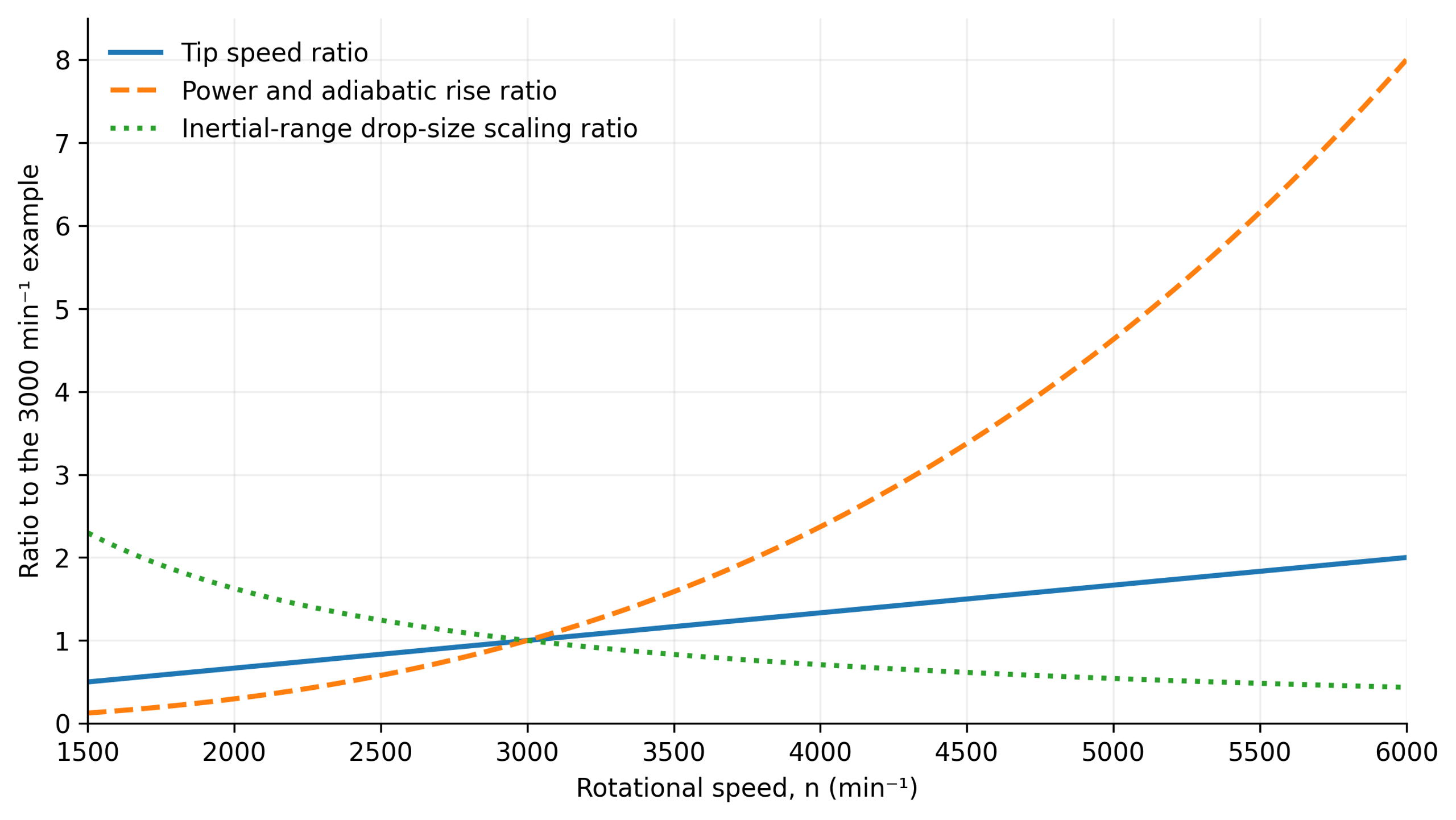
Figure 10.1. Calculated sensitivity relative to the 3000 min⁻¹ reference case. Diameter, throughput, liquid properties, power number, volume of the active zone, and local power fraction are held constant. The curves represent assumed scaling laws, not measured equipment performance [1].
Uncertainty in volume of the active zone can dominate local calculation. A twofold change in local dissipation changes the inertial range droplet diameter estimate by a factor of 0.758, whereas doubling interfacial tension increases it by approximately 1.52. These sensitivities identify the most useful measurements. Geometry specific power data, material properties at processing conditions, and a defensible definition of the active region are more informative than a nominal shear rate reported with unwarranted numerical precision.