
Technical publication
Back to publications
Reactors & equipment
Cavitation-Assisted Particle Dispersion
okozyuk.com
Published
Read complete publication for whole-document Find and printing. Browser Find and native printing on this reader include only loaded content.
6 Cavitation equipment for particle processing
6.1 General classification
Particle processing devices range from simple orifice plates to high-pressure micron-scale nozzles and dynamic rotor stator processors. The equipment determines the pressure history, bubble cloud structure, residence time in the collapse region, exposure uniformity, erosion risk, and scale-up method.
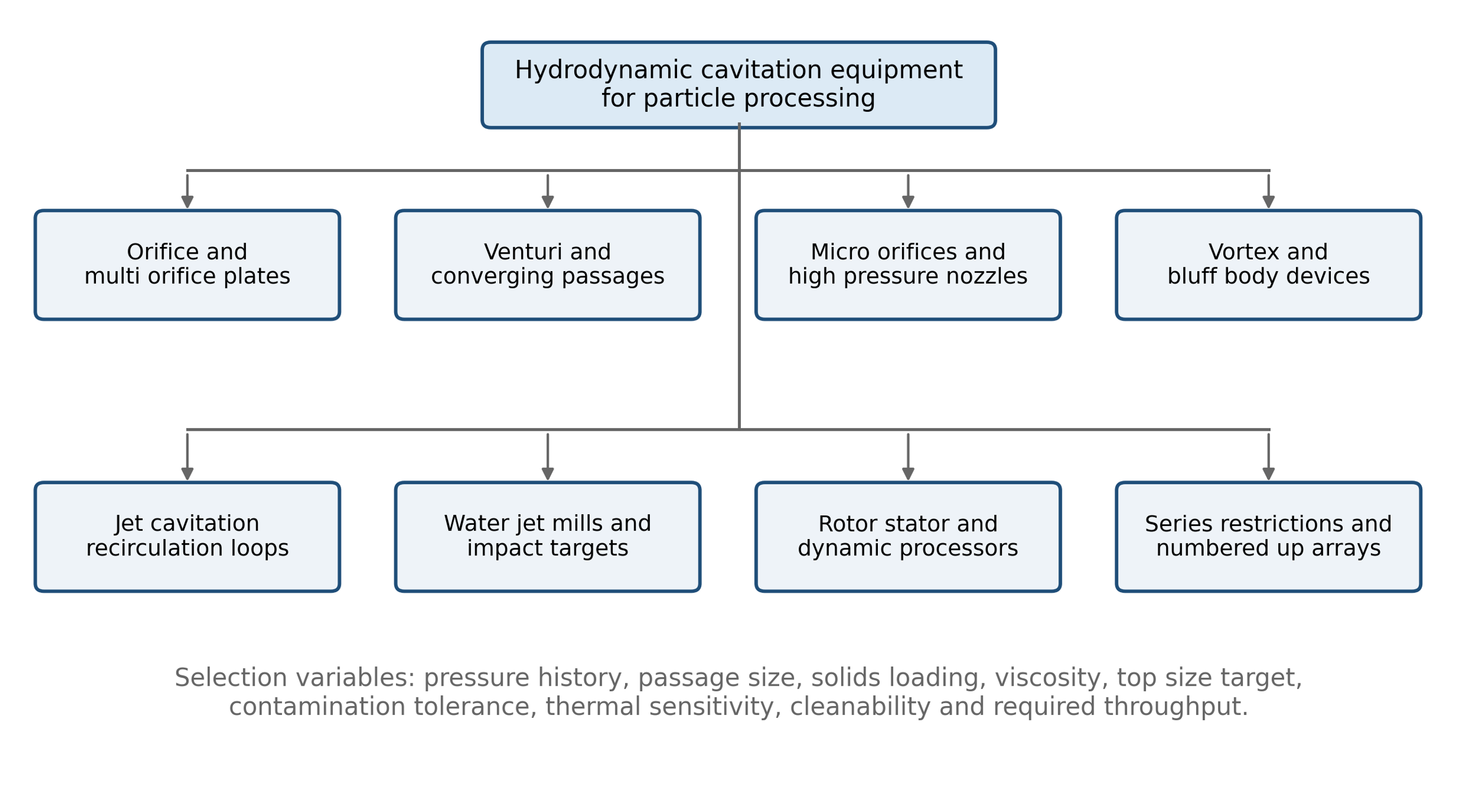
Figure 6.1. Classification of hydrodynamic cavitation equipment used for particle dispersion and deagglomeration [58].
Table 6.1. Comparison of equipment classes.
| Equipment class | Principal advantage | Main limitation | Suitable applications |
|---|---|---|---|
| Orifice or multi orifice plate | Simple, inexpensive, scalable, replaceable | Broad exposure distribution, plugging, erosion | Low to moderate viscosity slurries and multiple pass treatment |
| Venturi | Controlled pressure recovery and lower permanent loss | Geometry specific inception and long cavities | Continuous processing where energy recovery matters |
| Micro orifice or microchannel | High acceleration and precise passage size | Fouling, plugging, limited flow per channel | Dilute nanofluids and fine particle systems |
| High pressure nozzle | Very high velocity and stress in one pass | Pump cost, nozzle wear, temperature rise | Difficult nanoparticle agglomerates and narrow top size targets |
| Jet cavitation loop | Modular generators, recirculation, cooling | Pass distribution must be controlled | Exfoliation, comminution, pilot and production loops |
| Water jet mill | Combines cavitation, shear, impact, and classification | High pressure and complex solids handling | Brittle particles and intentional nanomilling |
| Dynamic rotor stator processor | High throughput and tolerance for viscous liquids | Mechanical seals, gap wear, scale up complexity | Production processing and concentrated formulations |
6.2 Orifices, Venturis, and vortex chambers
A sharp orifice creates a vena contracta downstream of the plate. Velocity reaches a maximum and static pressure reaches a minimum near this location. Cavities form in low pressure region and collapse as the jet expands. A Venturi provides a more gradual pressure reduction and recovery, often with a lower irreversible pressure loss. Multi orifice plates distribute flow among smaller passages and can increase the number of active cavity zones. Vortex chambers generate low pressure cores through angular momentum rather than a single axial contraction.
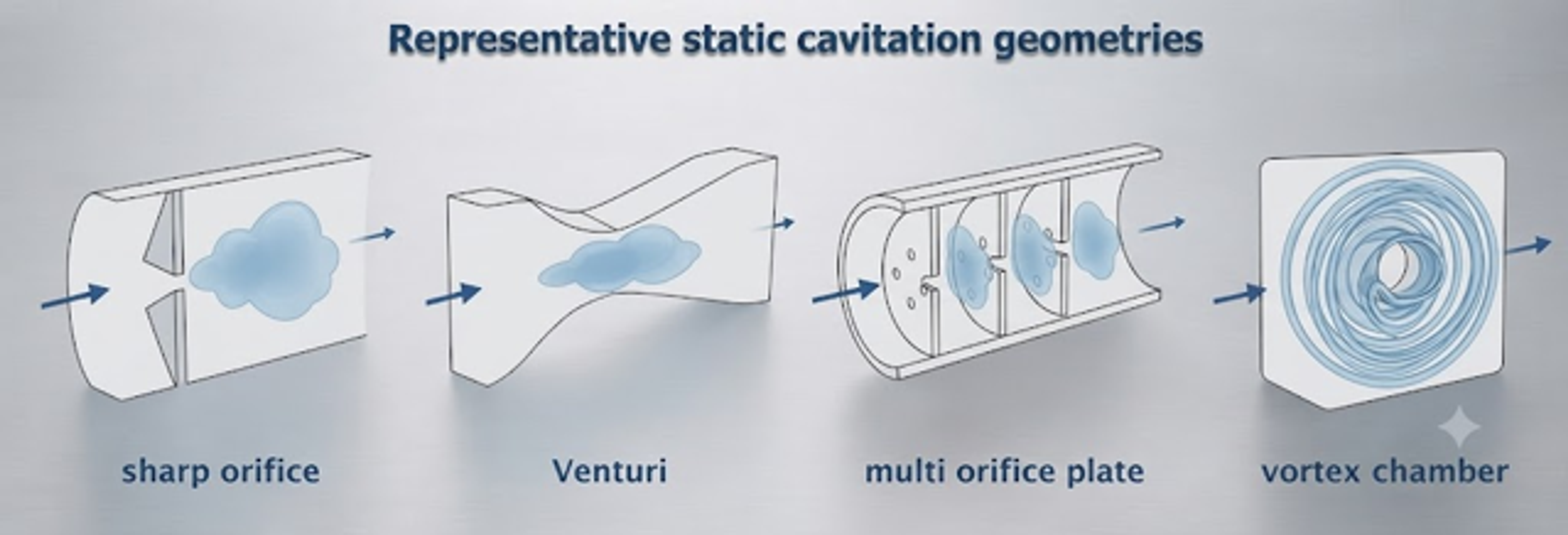
Figure 6.2. Representative static hydrodynamic cavitation geometries [58].
The minimum passage dimension must be selected relative to the incoming coarse tail. A passage only slightly larger than is vulnerable to plugging, bridging, and rapid erosion. Staged processing can first remove large agglomerates in a robust passage and then use a finer high intensity stage.
6.3 High-pressure nozzles and interaction chambers
High pressure nozzle systems convert pump pressure into a high-velocity jet through passages commonly measured in tens to hundreds of micrometers. Studies of high-pressure homogenization commonly report operation at approximately 100 to 500 bar, with particle size decreasing as pressure and the number of passes increase [14]. Solids may be introduced downstream of the pressure generating pump when exposure of the pump to abrasive material must be minimized. The critical design task is to place the strongest hydrodynamic loading at the contraction and the principal bubble collapse in a downstream chamber where particles are present, but wall erosion remains manageable.
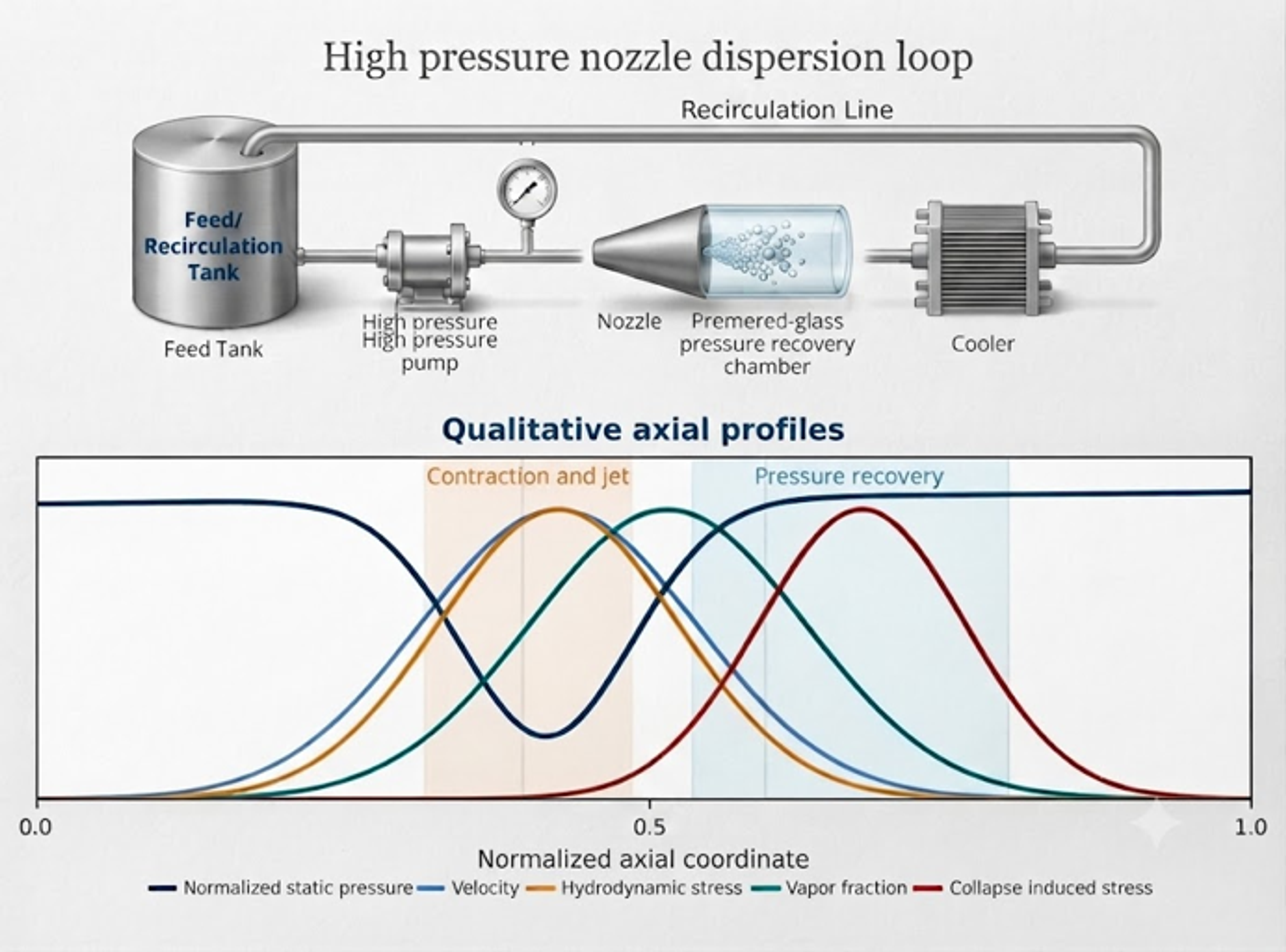
Figure 6.3. High pressure nozzle dispersion loop and qualitative axial profiles of pressure, velocity, vapor fraction, hydrodynamic stress, and collapse-induced stress [58].
At sufficiently high fragmentation number, rapid rupture or shattering can dominate over gradual erosion. At lower pressure, higher viscosity, or greater agglomerate strength, more passes may be needed, and the response may become controlled by erosion.
6.4 Micro-orifice and cavitation-on-chip systems
Micro orifice systems direct an agglomerated nanofluid through a short restriction. The passage is selected so that bubbles form near or after the restriction and collapse in a downstream recovery region rather than on the passage wall. Karimzadehkhouei and coworkers used a short channel with a characteristic size near 152 micrometers for alumina nanofluids [23]. Talebian Gevari and coworkers later visualized cavitation and particle breakup in a microfluidic device of similar scale [24].
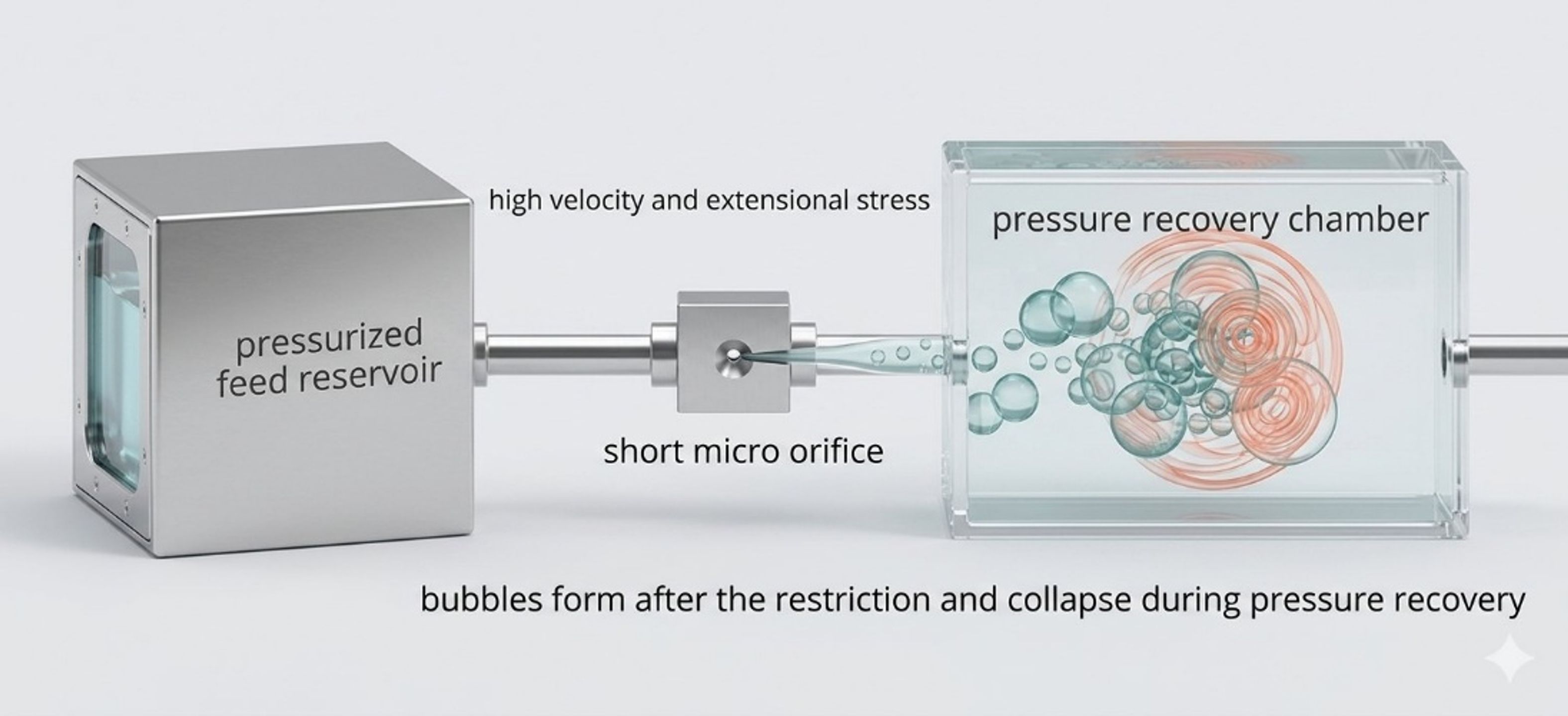
Figure 6.4. Schematic of a cavitation configuration with a short restriction and downstream collapse region [58].
The related patent describes one or more restrictive elements, optional heating, and series configurations intended to reduce or prevent nanofluid agglomeration [25]. Patent descriptions are useful for equipment architecture but should not be treated as independent validation of performance.
6.5 Water jet mills
A water jet mill combines rapid shear, cavitation bubble collapse, direct particle impact, recirculation, and classification [30]. The reported prototype used water pressure near 400 MPa and a nozzle diameter near 0.23 mm. Coarse material was returned to the milling cycle while the fine fraction was separated. Because hard target impact and classification contribute, this device should be described as an integrated cavitation mill rather than a pure deagglomerator. Earlier cavitation studies on ceramic powders also reported nanoscale titania and zirconia products [39].
6.6 Jet cavitation devices
Jet and microfluidic cavitation devices have been used to exfoliate graphite and related layered solids [31–33,40]. A typical loop contains a feed or recirculation reservoir, pressure source, micro restriction or cavitation generator, downstream recovery chamber, cooler, and return line. Shear in the contraction acts mainly parallel to the sheets, while pressure recovery and bubble collapse add normal and oblique loading. Repeated exposure can progressively reduce layer count, but excessive cycling can reduce lateral dimension or increase defects.
A patent by Ayela and Colombet describes a first small hydraulic diameter section that generates shear and bubbles, followed by a larger section in which bubbles implode and assist exfoliation [34].
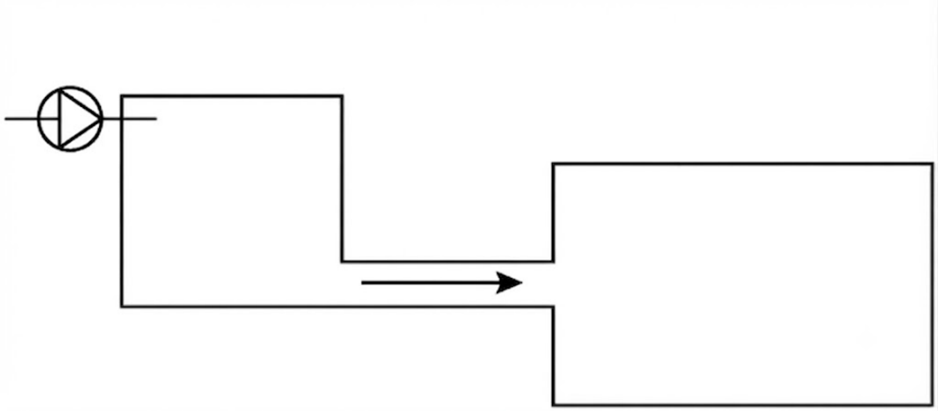
Figure 6.5. Patent drawing of a two-section flow path for particle exfoliation [34].
The patent specifies a first section hydraulic diameter below 300 micrometers, with preferred values below 150 or 90 micrometers. The design objective is to combine shear and a controlled collapse wave while limiting in-plane fracture [34].
6.7 Dynamic cavitation processors and production skids
Dynamic processors use rotating disks, perforations, teeth, grooves, blades, or rotor stator gaps to create repeated low pressure zones and recovery regions. Compared with static restrictions, they can process higher flow at lower external pressure and may tolerate more viscous formulations. Their performance is governed by tip speed, gap size, stage count, rotor geometry, gas management, and recirculation. Mechanical power includes useful liquid work and parasitic losses in bearings, seals, and bulk circulation.
A production skid normally includes a feed or recirculation tank, pump, pressure control, heat exchanger, cavitation reactor, sampling ports, relief devices, and optional filtration or classification. Abrasive solids require replaceable wear inserts, pressure-resistant bypass lines, and a monitoring plan for elemental contamination. Cleaning design becomes critical when the allowable top size approaches the smallest flow passage.